The difference between an old welding transformer and a new inverter welder is about the same as between the first Daimler Benz cars and a modern Mercedes. The inverter is much lighter than its heavy-duty predecessor and has built-in functions that previously could only be dreamed of, for example, the ability to control the welding current value or a function to prevent electrode sticking. But the brilliantly conceived idea has a significant drawback - the electronic filling fails much more often than the “oldies”, and repairing inverter welding machines requires considerable knowledge and skills. Any attempt to repair equipment blindly, without preparation, is fraught with fire or even injury.
The main breakdowns of welding machines and how to fix them
It is well known that the repair of welding machines in the vast majority of cases can be organized and carried out independently.
The only exception is the restoration of the electronic inverter, the complexity of the circuitry of which does not allow for a full repair at home. Just trying to disable the inverter protection can baffle even an electrical specialist. So in this case, it is best to seek help from a specialized workshop.
Frequent malfunctions
The main manifestations of problems with electric arc welding machines are:
- the device does not turn on when connected to the mains and started;
- sticking of the electrode with a simultaneous hum in the area of the converter;
- spontaneous shutdown of the welding machine in case of overheating.
Repairs always begin with an inspection of the welding machine and checking the supply voltage. Repairing transformer welding machines is not difficult, and they are not picky about maintenance. With inverter devices, it is more difficult to determine a breakdown, and repairs at home are often impossible.
However, if handled properly, inverters last a long time and do not break down. It is necessary to protect from dust, high humidity, frost, and store in a dry place. There are the most typical malfunctions of welding machines that you can fix yourself.
The device does not start
In this case, first of all, you need to make sure that there is voltage in the network and the integrity of the fuses installed in the transformer windings. If they are in good condition, you should use a tester to ring the current windings and each of the rectifier diodes, thereby checking their performance.
If one of the current windings breaks, it will need to be rewinded, and if both are faulty, it is easier to replace the entire transformer. The damaged or “suspicious” diode is replaced with a new one. After repair, the welding machine is turned on again and checked for serviceability.
Sometimes the filter capacitor fails. In this case, the repair will consist of checking it and replacing it with a new part.
If all elements of the circuit are in working order, it is necessary to deal with the mains voltage, which can be greatly underestimated and is simply not enough for the normal functioning of the welding machine.
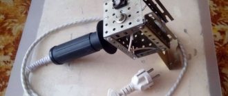
Electrode sticking (arc interruption)
The cause of electrode sticking and arc interruption may be a decrease in voltage due to a short circuit in the transformer windings, faulty diodes or loose connecting contacts. A breakdown of the capacitor filter or short circuit of individual parts to the body of the welding machine is also possible.
Organizational reasons due to which the machine does not weld as it should include the excessive length of welding wires (more than 30 meters).
If sticking is accompanied by a strong hum from the transformer, this also indicates an overload in the load circuits of the device or a short circuit in the welding wires.
One of the repair options to eliminate these effects could be restoring the insulation of connecting cables, as well as tightening loose contacts and terminal blocks.
Spontaneous shutdown
In some cases, repairs can be carried out independently if the device begins to turn off spontaneously. Most models of welding machines are equipped with a protective circuit (automatic) that is triggered in a critical situation, accompanied by a deviation from normal operation. One of the options for such protection involves blocking the operation of the device when the ventilation module is turned off.
After spontaneous shutdown of the welding machine, first of all, you should check the state of the protection and try to return this element to working condition.
If the protective unit is triggered again, it is necessary to proceed to troubleshooting using one of the methods described above related to short circuits or malfunctions of individual parts.
In this situation, first of all, you should make sure that the cooling unit of the unit is working normally and that overheating of the internal spaces is excluded.
It also happens that the cooling unit does not cope with its functions due to the fact that the welding machine was under a load for a long time that exceeded the permissible norm. The only correct solution in this case is to let it “rest” for about 30-40 minutes, and then try to turn it on again.
In the absence of internal protection, a circuit breaker can be installed in the electrical panel. To maintain normal functioning of the welding unit, its settings must correspond to the selected modes.
Thus, some models of such devices (welding inverter, in particular), in accordance with the instructions, must work according to a schedule that requires a break of 3-4 minutes after 7-8 minutes of continuous welding.
Malfunctions of inverter devices
Before repairing an inverter welding machine with your own hands, it is advisable to familiarize yourself with the principle of operation, as well as its electronic circuit. Knowing them will allow you to quickly identify the causes of breakdowns and try to eliminate them in a timely manner.
Electrical diagram
The operation of this device is based on the principle of double conversion of the input voltage and obtaining a direct welding current at the output by rectifying the high-frequency signal.
The use of an intermediate high-frequency signal makes it possible to obtain a compact pulse device that has the ability to effectively regulate the output current.
Failures of all welding inverters can be divided into the following types:
- malfunctions associated with errors in choosing the welding mode;
- operational failures caused by failure of the electronic (converter) module or other parts of the device.
The method for identifying inverter malfunctions associated with disturbances in the operation of the circuit involves sequential execution of operations carried out according to the principle “from simple damage to more complex damage.” The nature and cause of breakdowns, as well as repair methods, can be found in more detail in the summary table.
It also provides data on the main welding parameters, ensuring trouble-free (without turning off the inverter) operation of the device.
Features of operation
Maintenance and repair of inverter-type welding machines differs in a number of features related to the complexity of the circuitry of these electronic units. Repairing them will require certain knowledge, as well as the ability to handle measuring instruments such as a digital multimeter, oscilloscope and the like.
In the process of repairing an electronic circuit, a visual inspection of the circuit boards is first carried out in order to identify burnt or “suspicious” elements within individual functional modules.
If during the inspection no violations can be detected, the troubleshooting continues by identifying violations in the operation of the electronic circuit (checking voltage levels and the presence of a signal at its control points).
To do this, you will need an oscilloscope and a multimeter, which you should start working with only if you have complete confidence in your abilities. If you have any doubts about your qualifications, the only right decision is to take (take) the device to a specialized workshop.
Specialists in the repair of complex pulse devices will quickly find and eliminate the malfunction, and at the same time carry out maintenance of this unit.
Self-repair procedure
If you decide to repair the board yourself, we recommend using the following advice from experienced specialists.
If burnt wires and parts are discovered during a visual inspection, you should replace them with new ones, and at the same time reconnect all connectors, which will eliminate the possibility of loss of contact in them.
If such repairs do not lead to the desired result, you will have to begin a block-by-block examination of the electronic signal conversion circuits.
To do this, it is necessary to find sources that provide voltage and current diagrams intended for a more complete understanding of the operation of this unit.
Focusing on these diagrams using an oscilloscope, you can sequentially check all electronic chains and identify a node in which the normal signal conversion pattern is disrupted.
One of the most complex components of an inverter welding machine is the electronic key control board, the serviceability of which can be checked using the same oscilloscope.
If you have doubts about the functionality of this board, you can try replacing it with a working one (from another, working inverter) and try to start the welding machine again.
If the outcome is favorable, all that remains is to send your board for repair or replace it with a purchased new one. The same should be done if there are suspicions about the serviceability of all other modules or blocks of the welding machine.
In conclusion, let us recall that the repair of any welding units (and inverters, in particular) is considered a rather complex procedure that requires certain skills and the ability to handle complex measuring equipment.
If you have the slightest doubt about your professionalism, you should use the help of specialists and give them the opportunity to return the faulty device to work.
Possible malfunctions and their causes
The causes of problems with the inverter may arise due to:
- malfunction of the inverter itself;
- unsatisfactory condition of welding cables and device power circuit.
Functionality of the welding inverter.
Thermal deformation and voltage at the output of the device are inextricably linked. Due to voltage surges, the temperature of the arc changes, the metal either does not warm up to the required temperature, or burns out, forming slag and pores. Troubleshooting methods depend on the problem found. The simplest reason may be poor contact in the connections of the welding cables with alligator clips and plugs for connecting to the inverter. It leads to the appearance of deformations during welding. Typically, such a defect manifests itself in sharp non-periodic jumps in the welding current, spontaneous attenuation of the arc, which can lead to poor-quality connections, deformation and stress when welding parts from uneven heating.
The solution is simple and can be done independently. To eliminate it, you need to remove the protective insulating handles, disconnect the cable and inspect the connection points. If there are oxides and traces of heating, the surfaces must be cleaned with emery cloth and assembled, carefully tightening the connecting bolts. Cables with broken or broken wires and damaged insulation must be replaced with similar ones. It is better to keep the cable length the same. Many inverter models are designed for a strictly defined inductive reactance load and can change the operating parameters when the cable length changes.
The next reason may be a malfunction of the device itself. To determine the operability of the device, it is necessary to measure the voltage at the output terminals of the inverter and the voltage in the supply network with the device. At normal mains voltage, a low voltage at the inverter output will indicate a malfunction of the device. It is better to entrust inverter repair to specialists from the service center.
If the voltage at the inverter output is within acceptable limits at normal supply voltage, you should carefully check the supply voltage supply circuit to the device from the power supply input point or meter. The minimum power consumption of devices in welding mode is within 4-5 kW. The required cross-section of copper supply wires for such power must be at least 2.5 mm 2 with a long-term permissible operating current of 25 A throughout the entire power circuit. A cable with a smaller cross-section will heat up quickly and the voltage loss on it will increase.
It is imperative to check the quality of all connections along the power supply circuit. Weak twisting or other types of poor-quality connections can also create problems during welding work and lead to fire. Detachable connections from a plug-socket pair must be of a new type with an increased diameter of electrically conductive pins on the plugs. Old type forks cannot withstand the load under long-term operating conditions. Sockets must also be of the appropriate type. The length of the power supply lines cannot be more than 50 m, unless otherwise specified in the technical documentation for the device.
In rural areas, abnormal operation of inverters is often observed due to overloaded common power lines and low network voltage.
If, when trying to ignite an arc, the supply voltage drops to an unacceptably low value at the input point, this indicates insufficient capacity of the common line and its overload.
Sometimes voltage stabilizers can help in such a situation. The effectiveness of stabilizers also depends on several reasons and is not always justified. The total power consumption of the kit from the power supply network will be the power of the welding device plus losses in the stabilization device. Electricity costs will increase, overload of common lines will increase, which will further reduce the input voltage.
Before deciding to use such a device in conjunction with welding equipment, it is advisable to contact the electrical network with a written statement about poor-quality power supply.
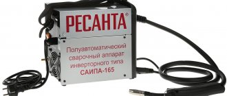
Repair of welding inverters: device malfunctions and how to check a semi-automatic machine
Many home workshops are equipped with welding equipment based on an inverter power supply. Such products have many advantages. However, from time to time any equipment breaks down and repair of welding inverters may be required.
Such an operation can be easily performed at home, since the internal layout of the inverter installation for igniting the arc is easy to diagnose and maintain. The success of correcting inverter welding faults depends, first of all, on the skills and knowledge of the repairman.
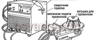
Features of welding inverters and their repair
The inverter-type semi-automatic welding machine has a number of features and advantages.
Most users of such welding devices note:
- high installation power;
- mobility of the device;
- ease of maintenance;
- reliability of the inverter design;
- minimum consumption of electrical energy when performing work on welding metal products.
A characteristic feature of inverter welding devices is a more complex electrical circuit compared to transformer or rectifier welding.
Inverter for welding work.
Repair of inverter welding machines should begin by checking the following elements:
- transistors;
- diode bridge;
- cooling system.
Before you repair welding machines yourself, you need to diagnose the main components. Typically, faulty parts, such as transistors or diodes, can be easily identified by a significant change in geometry.
If such parts can be identified visually, then restoring a welding machine with your own hands will come down to a banal replacement of faulty electrical elements using a soldering iron and solder.
Most models of inverter welding machines come with instructions. It is easier to carry out maintenance of these devices using the diagrams available in the corresponding section of the documentation.
Diagnosis of inverter faults
Immediately before restoring the functionality of inverter welding equipment, you should familiarize yourself with typical faults and the most effective diagnostic methods.
In most cases, repair of semi-automatic welding machines should be carried out according to the following algorithm:
- Visual inspection of all inverter components.
- Cleaning oxidized contacts using a solvent and a brush.
- Studying the design of the inverter using the documentation included in the kit.
- Fault diagnosis.
- Replacement of non-working electronic components.
- Test run.
Functional diagram of a welding inverter.
All malfunctions that may require DIY repair of welding machines are divided into three types:
- arising due to incorrect choice of welding mode;
- arising due to a malfunction of one of the elements of the electronic circuit of the device;
- caused by dust or foreign objects entering the housing of the inverter power supply.
Before checking the welding machine for faulty radio components, you should completely clean it of dust and dirt. Clogging of the cooling elements of the arc support system can adversely affect the performance of many electronic components.
If a preliminary visual check does not reveal any malfunctions, then you should proceed to a more in-depth diagnosis.
Typical reasons for inverter failure are presented:
- liquid entering the inverter housing, resulting in oxidation of the conductive paths and corrosion of the main radio elements;
- an abundance of dust and dirt inside the case, as a result of which the cooling significantly deteriorated and the power microcircuits overheated;
- overheating of the inverter due to the selection of an incorrect operating mode, which may require repair of welding rectifiers.
Repairing a welding transformer, unlike an inverter, can be performed without significant skills and abilities. Transformer assemblies use radioelements that have an incredibly long life cycle.
The repair technique for the converter and other key components of the inverter current source will be shown in the next section.
Main types of breakdowns and their elimination
Before considering the main types of malfunctions of inverter devices, you should familiarize yourself with the inverter device.
Electrical circuit of a welding inverter.
Most popular models consist of:
- power supply;
- control unit;
- power block.
Malfunctions and repairs of welding machines in most cases are associated with a breakdown of the power unit, consisting of:
- Primary and secondary rectifiers. The block includes two diode bridges of varying power. The first bridge is capable of withstanding up to 40 amperes of current and up to 250 volts of voltage. The second diode bridge is assembled from more powerful elements and is capable of maintaining a current of 250 amperes at a voltage of about 100 volts. Possible errors of this module are associated with failure of the diodes of the primary or secondary bridge.
- Inverter converter. A breakdown of the power transistor of the inverter converter is often the answer to the question why the welding machine does not weld. The inverter can be repaired by replacing the transistor with an analogue one with a current rating of 32 amperes and a voltage of 400 volts.
- High frequency transformer. Typically, a transformer consists of several windings that increase the current to 250 amperes at a voltage of up to 40 volts. Most inverter equipment has two windings made using copper wire or tape.
Before you repair welding machines with your own hands, you should carefully diagnose the device and clearly determine which of the elements is faulty.
You shouldn’t even try to repair an inverter yourself from which thick white smoke is pouring out of the housing. In such cases, the best solution would be to contact a qualified repair center.
Layout of welding inverter parts.
Repair of a semi-automatic welding machine with an inverter source may be necessary if the following malfunctions occur:
- Unstable burning of a hot arc or strong spattering of the electrode material. The malfunction in most cases is due to the incorrect choice of operating current. The operating instructions say that per 1 millimeter of electrode diameter there should be a current of 20 to 40 amperes.
- Adhesion of welding to metal. This behavior is typical for devices operating at insufficient voltage. Such malfunctions and methods for eliminating them are clearly described in the accompanying documentation. If the electrode sticks to the material being welded, clean the terminal contacts to which the inverter device modules are connected. In addition, it would not be superfluous to measure the voltage in the electrical network.
- No arc when turning on the equipment. The defect is often associated with simple overheating of the device or damage to the power cables during long-term operation at elevated temperatures.
- Inverter emergency shutdown. If during the work the device suddenly turns off, then the short circuit protection between the wires and the housing has probably worked. Repairing the device in the event of such a defect consists of finding and replacing damaged elements of the inverter power circuit.
- Huge consumption of electric current during idle operation. A typical malfunction that occurs due to the short circuit of the turns on the current-carrying coils. Restoring the device's functionality after such a malfunction consists of completely rewinding the coils and applying a layer of additional insulation.
- Switching off welding equipment after a certain period of time. This behavior is typical for overheating inverter electrical appliances. If the welding suddenly turns off, then you need to let it cool down and after 30-40 minutes you can continue working.
- Extraneous sounds when the power supply is operating. Elimination of the defect consists of tightening the bolts holding together the magnetic guide elements. In addition, the malfunction may be due to a defect in the core fastener or a short circuit between the cables.
Recommendations for DIY repairs
Electrical circuit of the welding machine.
When repairing inverter-type welding machines, you should adhere to a certain algorithm:
- If a malfunction occurs, you must immediately disconnect the electrical device from the network, allow it to cool, and only then open the metal casing.
- Diagnostics must begin with a visual inspection of the electrical components of the inverter. There are often cases when repairing an inverter welding machine involves simply replacing damaged parts or soldering conductive contacts. Visually enlarged capacitors or cracked transistors should be replaced first.
- If a visual inspection fails to determine the cause of the malfunction of the welding machine, you must proceed to checking the parameters of the parts using a multimeter, voltmeter and oscilloscope. The most common failures of power units are associated with malfunction of transistors.
- After replacing the electrical elements, it is worth moving on to checking the printed conductors located on the inverter board. If you find torn or damaged tracks on the printed circuit board of a welding tool, you must immediately eliminate the defect by soldering jumpers or restoring the tracks using copper wire of the required cross-section.
- After completing work with the tracks, it makes sense to move on to servicing the connectors. If the inverter device stopped working gradually, then there may be poor contact in the connecting connectors. In this case, it is enough to measure all contacts with a multimeter and clean the connectors with an ordinary household eraser.
- Despite the fact that malfunctions of a welding inverter are rarely associated with diode bridges, it would be a good idea to check their performance. It is better to diagnose this electrical element in a soldered state. If all the legs of the bridge are short-circuited, then you should search for the faulty diode and replace it.
- The last step in inverter repair is checking the board and control panels. Diagnostics of all components of the board should be carried out using a high-resolution oscilloscope.
When performing independent repair work, you should not forget about the safety rules:
- Do not use electrical appliances without a protective top casing;
- all diagnostic and repair work should be carried out on completely de-energized equipment;
- It is safest to remove accumulated dust and dirt using an air flow generated by a compressor or a compressed gas cylinder;
- Cleaning of printed circuit boards must be done using neutral solvents applied to a special brush;
- Long-term storage of electrical appliances should be done in dry rooms and completely switched off.
Most inverter electrical appliances are supplied complete with accompanying documentation. In these papers you can find a description of the most common faults and repair methods. Therefore, if malfunctions occur, you should carefully study the documentation and only then begin repair work.
Conclusion
Self-repair can be done at home. The main malfunctions of inverters are associated with the choice of the wrong operating mode or failure of radio elements.
Some malfunctions of semi-automatic welding machines can be determined visually. There are only a few reasons why the welding inverter does not turn on. Most causes of failure of a working inverter are associated with burnt capacitors or broken welding transistors.
Inverter functions and design
The inverter device is an important component of the monitor. In the electronic circuit, it performs several functions that ensure normal operation of the screen:
- Converting 12 volt DC voltage into high voltage alternating voltage.
- Stabilization and regulation of the current supplied to the lamp.
- Adjust brightness within the required range.
- Matching its own output stage with the resistance of the lamps at the input.
- Protects against overloads and short circuits.
Despite the design features of various models, the general principles of the structure and operation of inverters are generally the same. Due to this, repairing and checking the inverter is greatly simplified.
A typical inverter circuit is shown in the figure below. The block that combines the standby mode and the function of turning on the device, made using keys Q1 and Q2, is clearly visible. As a rule, the monitor does not turn on immediately, but after a certain time, so the inverter also turns on with a delay. After moving the power button to the desired position, voltage from the main board is supplied to the inverter, and it begins to operate in operating mode. Using the same block, the inverter is turned off when the monitor is switched to economy mode.
When transistor Q1 receives the 3-5 volts needed to turn on, it opens and passes 12 volts to the main inverter circuit. It consists of a PWM controller (3) and a unit responsible for brightness control (2).
Voltage from the main board is supplied to this block from the brightness control. Further, as a result of transformations, it becomes equal to the feedback voltage and generates an error signal that sets the pulse frequency on the PWM. Pulses are used to control the DC/DC converter (1) and synchronize the converter. Their amplitude is always at the same level and depends on the supply voltage of 12 V. The pulse frequency is influenced by the maximum voltage and brightness voltage.
The DC/DC converter maintains the high voltage state supplied to the autogenerator at the same level. The generator is turned on and controlled by PWM pulses. The alternating voltage of the inverter at the output depends on the characteristics of the elements used in the circuit, and the frequency indicators are determined by the parameters of the backlight lamps and the brightness control.
Analysis of the level of output current or voltage is performed by the protective unit (5, 6), after which it generates feedback and overload voltages that enter the control unit (2) and PWM (3). In case of overloads and short circuits, any of the voltages may exceed the threshold value. This leads to automatic shutdown of the generator.
In the screen layout, the main elements - the control unit, PWM and the control unit - are combined into a common chip. The converter uses discrete elements, and a pulse transformer with an additional winding is installed as a load, which switches the voltage during startup.
Inverter welding does not turn on
It is well known that the repair of welding machines in the vast majority of cases can be organized and carried out independently. The only exception is the restoration of the electronic inverter, the complexity of the circuitry of which does not allow for a full repair at home.
Just trying to disable the inverter protection can baffle even an electrical specialist. So in this case, it is best to seek help from a specialized workshop.
Disadvantages of SAI inverters
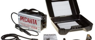
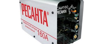
Consumers, as a rule, believe that the name of the welding machine indicates the maximum welding current and it must correspond to the indicators of this current de facto, in practice. Numerous tests show that the declared maximum current does not always correspond to the actual value and can differ by up to 10 percent. This means that at a maximum current of 190, 170...180A will be available, which in many cases is not of fundamental importance for welding at home .
It should also be noted that the inverter models SAI190, SAI220 and SAI250 actually differ from each other by the inscription on the case. This means that the maximum welding current for all these devices will be approximately the same (the difference will only be in the short circuit current and the number of capacitors: SAI190 has three, SAI 250 has four) and PV is 40%.
The welding inverter does not turn on. DIY repairs. Scheme
Hi all!!! The other day a welding inverter was brought in for repair; perhaps my note about this repair will be useful to someone.
This is not the first welding machine that had to be made, but in one case the malfunction manifested itself like this: I turned on the inverter to the network... and boom, the circuit breakers in the electrical panel were knocked out. As the autopsy showed, the output transistors were broken in the welder, after replacement everything worked.
But in this case, everything was somewhat different; according to the owner, the device sometimes stopped cooking, although the power indicator was on.
These guys opened the case themselves - they tried to determine the malfunction and noticed that the inverter reacted to the bending of the board, i.e. by bending it I could earn it.
But when the welding inverter came to me, it no longer turned on at all, even the power indicator did not light up.
Welding inverter does not turn on
“Titan - BIS - 2300” - this is the model of inverter that was sent for repair, the circuitry is the same as a welding machine of similar power “Resanta” and, as I assume, many other inverters. You can view and download the diagram here.
This welding machine uses a switching power supply to power low-voltage circuits, and it was precisely this that was faulty. The UPS is made on a PWM controller UC 3842BN.
Analogues - domestic 1114EU7, imported UC3842AN differs from BN only in lower current consumption, and KA3842BN (AN). The UPS diagram is below. (Click on it to enlarge) The voltages that were produced by the already working UPS are marked in red.
Please note that you need to measure 25V voltages not relative to the common minus, but from points V1+,V1- and also V2+,V2-, they are not connected to the common bus.
The UPS switch is made on a transistor, field switch 4N90C. In my case, the transistor remained intact, but the microcircuit required replacement. There was also a break in resistor R 010 - 22 Om/1Wt. After this the power supply started working.
However, it was too early to rejoice, having measured the voltage at the output of the welder, it turned out that there was none, and in idle mode it should be approximately 85 volts. I tried to move the board, remember from the owner’s words it had an effect, but nothing.
Further searches revealed the absence of one of the 25 volt voltages at points V2-, V2+. The reason is a break in the transformer winding 1-2. I had to unsolder the trans, I used a medical needle to release the leads.
In the transformer, one of the ends of the winding was broken from the terminal.
We carefully restore the connection using a suitable wire; it will not be superfluous to fix the restored connection with a drop of glue or sealant. I happened to have some polyurethane glue on hand and used it to check other conclusions and solder them if necessary.
Before installing the transformer, you should prepare the board so that it fits into place without effort. To do this, you need to clean the holes from any remaining solder; this can also be done with a needle from a syringe of a suitable diameter.
After installing the transformer, the welding inverter started working.
How to check the microcircuit
How to check a microcircuit without desoldering it from the board and what else to pay attention to.
You can partially check the microcircuit if you have a voltmeter and an adjustable stabilized constant voltage source. A signal generator and an oscilloscope are required for a complete test.
Let's talk about what is simpler. Before checking, be sure to turn off the inverter from the power supply. Next, from an external regulated power supply we supply a voltage of 16 - 17 volts to pin 7 of the microcircuit, this is the MS startup voltage. In this case, there should be 5 V at pin 8. This is the reference voltage from the internal stabilizer of the chip.
It should remain stable when the voltage on pin 7 changes. If this is not the case, the MS is faulty.
When changing the voltage on the microcircuit, keep in mind that below 10 V the microcircuit turns off and turns on at 15-17 volts. You should not increase the supply voltage of the MS above 34 V. There is a protective zener diode inside the microcircuit, and if the voltage is too high, it will simply break through.
Below is the block diagram of UC3842.
Addition to this article: After some time they brought another device. Out of service due to falling on its side.
This happened because during operation the screws holding the case became loose, and some were simply lost, so when dropped, the board played and touched the case with the mounting side. As a result of the short circuit, all 4 output transistors K 30N60HS Analogs G30N60A4D, G40N60UFD failed. After the replacement everything worked.
That's all! If you found this article useful, leave your comments and share with friends by clicking on the social network buttons.
Repair process
We solder the power transistors and driver wiring. We clean the contact pads from dirt, wash the board, prepare holes for the elements.
New elements were soldered. This is what proper soldering looks like. No frogs, pieces of rosin, etc. Quality repairs begin with careful soldering.
When soldering the drivers, it turned out that one of the 24 Ohm resistors was simply broken. Although it was visually invisible.
The soldering points of the inverter switching board are heavily oxidized, which led to a ring crack. Visible in the photo.
The ring crack was repaired. Carefully soldered the contact pads.
At the edges of the board there are transistors KSE 340 and KSE 350 with small radiators; compensating stabilizers of +- 15 Volts are assembled on them to power the control board (CP) and power the primary winding of the base transformer. Before turning on the inverter, even from a current source, you need to make sure that the power supply to the zener diodes is 15 Volts. A discrepancy of 0.3-0.5 Volts between the arms is allowed. We start the inverter board from the source, and connect the load emulator - a choke - as a load. It is prohibited to start the inverter without a load choke; the power transistors will immediately burn out. To turn it on, you need to close the optocoupler on the board (turn-on permission). Failed to start. After a long process, it turned out that the base transformer had failed. We install a new one.
The inverter board has been successfully launched. Hooray! Prepared for assembly. We wash, clean, and cover the board with a compound called Viksint.
This is the beauty we got.
We cover the transistors with an even layer of KPT-8 thermal paste; the surfaces of the transistors must be clean and dry. I would like to note that the thyristor requires insulation in the form of 2 layers of mica, each layer is coated with thermal paste.
Let's put everything back together. During the repair, we also installed a new fuse on the CC-tig board and replaced the cable on the control board; the cable lost its elasticity due to age, the insulation became stiff and began to crack.
When the high-voltage oscillator was turned on, there was no spark at the output. I had to remove the module, it turned out that the wire had come off the oscillator board. The blue wire is visible in the photo. We soldered it, riveted the corners of the module fastening, and at the same time cleaned the gas line of dirt; there was enough of it there; if you didn’t clean it, the pressure in the torch would not be enough for normal welding.
Repair of welding inverters: main faults
Reading time: 8 minutes
Over the past 20 years, inverter welding has become the most popular welding technology in existence. This is not surprising, because you can find inexpensive inverter models on sale, which, nevertheless, can teach you the basics of welding. Inverters are technologically advanced and modern, they give you more options compared to a classic welding transformer or rectifier.
Microcircuits are the heart of any inverter. It is thanks to microcircuits that manufacturers were able to introduce many new functions into the welding machine, as well as significantly reduce its dimensions and weight.
But we all know very well that the more complex the device, the more often it fails.
In this article we will list the main malfunctions of welding inverters and tell you how you can repair the welding machine yourself.
articles
Inverter sparks
one of the most common malfunctions in a budget inverter. Often under such circumstances the device sparks but does not cook. i.e., the arc is ignited for a split second and then goes out again. There can be many reasons for this breakdown. But first things first.
Start by carefully inspecting the welding cables you use in your welding. Often they are the problem. even if you do not see noticeable defects, connect other (preferably new) cables to the holder and ground, and try again why the arc is needed. also check that all connectors are secure.
If the inverter continues to spark, then the problem may lie in the electrolytic capacitors in the inverter. replace them if you have sufficient skills. If this doesn’t help, then look at the wires on the package. They may be burnt and need replacing.
In case of failure, it is better to take the device to a service center. because there may be a dozen reasons for this problem. At the service center you will be given a full diagnosis and will be able to find out the true cause.
inverter doesn't cook
The inverter welding machine may be turned on, all indicator lights may be normal, but welding is not taking place. The most common cause of such a breakdown is overheating of the device. We will talk about how to eliminate overheating below.
Also check the condition of the welding cables, they may be damaged or simply need to be replaced. connect new welding cables and try to check the operation of the machine again.
inverter overheats
one of the main reasons why a welding machine welds poorly or does not weld at all. If you cook for more than 10 minutes without a break, the device may overheat. Many inverters are equipped with overheating protection, but sometimes it does not work. then the inverter simply stops working, but remains turned on.
The problem can be solved very simply. stop welding for half an hour. leave the inverter to rest. in half an hour it will return to normal and you can continue working.
inverter does not work, does not turn on
Another one of the most common problems. you plug the device into the outlet, but it shows no signs of life. there may be several reasons. It's usually all about your mains voltage.
it may not be enough to turn on the welding machine. if you cook at the dacha, then the probability of low voltage at the output is very high.
The problem is solved by purchasing a voltage stabilizer and connecting it to the device.
Another reason is a problem with the network cable with which the device is connected to the outlet. Check the integrity of the cable and plug. You can remove the body of the device and see if everything is in order with the rest of the network cable, hidden from view.
If everything is fine with the cable, but the stabilizer did not help, then the cause of the malfunction is probably in the power supply of the inverter itself. In this case, we recommend contacting the service center. There is a high probability that you will not be able to repair the welding inverter at home without outside help.
current is not adjustable
you turn the current control, but nothing happens. Most likely, the problem lies in the regulator itself. you need to replace either the regulator or check the reliability of its connection to the wires. remove the device body and check everything carefully. Use a multimeter to diagnose the regulator.
if the regulator is working, but the current is not regulated, then the reason may be a shorted inductor or a malfunction of the secondary transformer. replace these components or take the device to a specialist. he knows what to do with it.
electrode sticks to metal
Many modern inverters are equipped with an “anti-stick” function, which prevents the electrode from sticking to the metal. but sometimes this function does not work correctly or does not work at all due to other device failures.
The first reason for the electrode sticking to the metal is an incorrectly selected welding mode. We talked in detail about how to set up the welding mode in this article.
the second reason is the same low voltage of your electrical network. There are inverters that can operate at reduced voltage. but in some places the voltage is so low that even such devices cannot cope with the work. The problem is solved by purchasing a voltage stabilizer.
the third reason is the use of welding extensions. Sometimes the welding cable is simply not long enough to complete the welding job. in this case, you can use a special extension cord. but keep in mind that if its length exceeds 40 meters and its cross-section is less than 2.5 mm2, then there is a high probability of a decrease in voltage during welding. and after this the adhesion of the electrode to the metal.
the fourth reason is poor preparation of the part before welding. for example, you are welding metal with an oxide film on the surface, but you did not clean the part thoroughly enough before performing the work. as a result, the film formed again and worsened the contact of the electrode with the metal, causing sticking
fault diagnosis
Let's add a few words about how to diagnose malfunctions in the device.
If you smell burning or smoke from the inverter housing, this is a signal of a very serious breakdown. We do not recommend diagnosing the device yourself in such a situation; it is better to take it to a service center. Eliminating such malfunctions requires many years of experience and understanding of all the nuances of the operation of the device.
If the breakdowns are less critical, you can do the diagnostics yourself. To do this, remove the housing and visually inspect all components of the device. Sometimes manufacturers produce models with poor-quality soldering or low-quality wires. In such cases, you can simply re-solder individual sections and the device will work properly.
Features of control board repair
The control board is one of the most complex and important elements of the entire device, because the operation of all other parts depends on the control board. An oscilloscope will be used first, and then a multimeter can be used.
This is what the control board of the Resanta SAI-220PN welding inverter looks like, if you don’t understand, it’s better to send it to specialists for repair
The switched-on welding inverter is checked in voltage mode up to 20 V. The regulator is turned to minimum, the black probe should be on the terminal, and the red probe should be on the sixth pin. When the regulator is brought to maximum, the voltage should also change. For example, if 160–200 A is assumed, then the change will be in the range of 2.4–3.2 V.
If problems are found, repairs can only be made if you know how to work with radio electronics.
Possible faults
The most common situation is when the image is displayed on the screen, but there is no backlight. You can only see something on the monitor from a certain angle or by illuminating the display with a bright flashlight.
The reasons for this screen condition may be the following:
- The backlight lamps are in faulty condition. The solution to this problem is very simple - you just need to replace the faulty element and check its functionality. If the required lamp is not available, a resistor with the most suitable power and resistance can be soldered into the circuit.
- The inverter that powers the backlight lamps needs to be repaired.
The second case is more complex, since the circuit of this device contains a large number of elements and each of them can fail. The circuit discussed above contains a high-voltage inverter transformer and many small parts - transistors, resistors, capacitors, etc. In most cases, the fault can be easily identified by the typical black marks left on the board.
During troubleshooting, do not touch the inverter and other electronic boards while the monitor is connected to the network. The greatest danger to life and health is posed by elements under voltage of 1500 V and above.
If the screen backlight is working properly, but there is still no image, you need to check the inverter on the monitor. There are two options to solve this problem:
- The monitor is connected to an external power supply connected to a separate inverter board. Typically, such a malfunction can be eliminated by simply replacing the part and connecting it to the controller board. This is quite possible, since the connectors of most devices are universal.
- In the second case, the monitor has its own built-in power supply, located together with the inverter on a common board. Here, different methods are used to solve the problem, which in most cases can only be done by specialists.
Causes of inverter failures
Modern inverters, especially those made on the basis of an IGBT module, are quite demanding in terms of operating rules. This is explained by the fact that when the unit operates, its internal modules generate a lot of heat. Although radiators and a fan are used to remove heat from power components and electronic boards, these measures are sometimes not enough, especially in inexpensive units. Therefore, you need to strictly follow the rules that are indicated in the instructions for the device, which imply periodically turning off the unit to cool down.
This rule is usually called “On Duration” (DS), which is measured as a percentage. Without observing the PV, the main components of the device overheat and fail. If this happens to a new unit, then this breakdown is not subject to warranty repair.
Also, if an inverter welding machine operates in dusty rooms, dust settles on its radiators and interferes with normal heat transfer, which inevitably leads to overheating and breakdown of electrical components. If the presence of dust in the air cannot be eliminated, it is necessary to open the inverter housing more often and clean all components of the device from accumulated contaminants.
But most often inverters fail when they operate at low temperatures. Breakdowns occur due to the appearance of condensation on the heated control board, resulting in a short circuit between the parts of this electronic module.
Checking and connecting the internal inverter to the power supply
Once the position and purpose of the contacts located on the boards have been determined, you can connect the inverter to the power supply and the board to the matrix controller.
The connection can be made in different ways:
- Directly from the connector by connecting wires to the output contacts.
- By inserting into the section of wire between the power supply and the controller board.
- The connection between the inverter and the power board is soldered.
The third method is most often used, so first you need to solder a separate wire to each contact. After this, they are insulated with heat-shrinkable tubes or electrical tape. Next, the inverter wires need to be connected to the conductors soldered to the power supply:
- Connecting the +12 pin to two VCC pins.
- Two GND pins on both devices.
- The BRIG and ADJ contacts are connected to each other.
- Both ON/OFF pins are also connected to each other.
The connected cards are connected to the monitor, and after turning on the computer, the functionality of the device is checked.
Source
How to identify connectors and pin assignments
The inverter board can be used from an old monitor or a new one can be purchased. The first option is much cheaper, but there is a risk that the part will not work. In the second case, the board will cost more, but the quality will be guaranteed by the manufacturer.
The board, which combines an external backlight inverter and a power supply, is equipped with only one connector that allows it to be connected to the matrix controller board. Knowing the purpose of the contacts on both boards, you can easily connect them using conductors. Many boards have a connection diagram with a decoding printed on them.
In the figure shown, the assignment of the power supply input connectors will look like this:
- Two +12 V contacts located on the left provide positive voltage.
- The middle GND contacts, two in number, correspond to negative or ground.
- Turning the screen on and off is provided by the ON/OFF contact located at the top right.
- The BRIG pin, located at the bottom right, is directly involved in controlling the monitor.
At the output, the inverter board has contacts arranged in one row from left to right and performing the following functions:
- Contacts GND – 2 units, just like at the input, are ground or minus.
- The ADJ pin controls the backlight.
- ON/OFF – turns the backlight on and off.
- The rightmost VCC pins allow positive voltage to pass through.
The contacts are connected in pairs; it is best if each of them is connected with a separate wire. If there is no circuit diagram with decoding on the board, it is recommended to find it on the Internet. In the search, you should indicate exactly the model of the board itself, and not the monitor.
The device does not start
In this case, first of all, you need to make sure that there is voltage in the network and the integrity of the fuses installed in the transformer windings. If they are in good condition, you should use a tester to ring the current windings and each of the rectifier diodes, thereby checking their performance.
If one of the current windings breaks, it will need to be rewinded, and if both are faulty, it is easier to replace the entire transformer. The damaged or “suspicious” diode is replaced with a new one. After repair, the welding machine is turned on again and checked for serviceability.
Sometimes the filter capacitor fails. In this case, the repair will consist of checking it and replacing it with a new part.
If all elements of the circuit are in working order, it is necessary to deal with the mains voltage, which can be greatly underestimated and is simply not enough for the normal functioning of the welding machine.
Main problems
The device does not work
Novice welders turn to a repair center for help at the moment when their machine simply does not turn on. This is not the best option, but it is common.
The inverter may not work for many reasons. Sometimes it may not even be a problem with the device, but with the network or another power source.
The voltage in them can “jump” or drop to a level too low for the welding machine. Because of this, the latter cannot even turn on.
The inverter turns off and goes into protection.
#1 Bvn
Hello. I recently started learning to become a welder. Some things work out, some things don’t work out so well. But there is one problem that no one can help me with. When I try to weld a part to a structure that has contact with the ground, the device is switched off and the protection is triggered. For example, weld hinges to a metal pole dug into the ground. Maybe this is a device glitch? Or am I doing something wrong?
- Top
- Insert nickname
#2 midtower
the device is switched off - protection is triggered
Are earthbenders worth the intrigue?
You should post a photo and a model, but the working conditions are outdoors: not all welding machines allow you to work without grounding, in damp conditions, and (possibly) throw old cables right through the mud. Some beat the welder, others commit suicide.
- 1
- Top
- Insert nickname
#3 Bvn
Thanks for the answer. Today I'll go to the dacha. I'll take photos of the device and post them. And the conditions are as follows: work without grounding, outside in good sunny weather (worked this summer). Welding machine "Cedar" MMA-220F.
- Top
- Insert nickname
#4 Denis Fedotov
welding and soldering workshop in Samara89270247227
- Participant
- Messages: 528
- Samara city
Thanks for the answer. Today I'll go to the dacha. I'll take photos of the device and post them. And the conditions are as follows: work without grounding, outside in good sunny weather (worked this summer). Welding machine "Cedar" MMA-220F.
- Top
- Insert nickname
#5 Bvn
Yes, of course the network sags. But a similar device “Resanta” (I don’t remember the parameters) cooks at the same time. And mine cooks if you cook parts isolated from the ground. And it turns off instantly. As soon as you touch it with the electrode, the protection is triggered. In order for the device to turn on, it must be completely turned off, including from the network, and turned on after 5-7 minutes. The ground terminal is fixed to a grounded part (on a pole).
- Top
- Insert nickname
#6 midtower
And mine cooks if you cook parts isolated from the ground.
If the cable insulation is in very good condition, then you need to place the welder on some dry plywood and a rubber mat. A stool. If this doesn’t help, then you definitely need to call Aang the priest shaman.
- 1
- Top
- Insert nickname
#7 Bvn
The insulation is in good condition, but the welder was standing on the ground. Maybe this is the reason? Although, it also happened that the welder stood in the gazebo on a dry wooden floor, and I leaned the parts to be welded against the metal support of the gazebo, which was dug into the ground. And the result is the same: when the electrode comes into contact with the part, the protection is immediately activated. I laid a piece of plywood between the part and the support and welded everything together. The contract is not grounded in all cases. The polarity is reversed.
Post edited by Bvn: 17 December 2021 12:09
- Top
- Insert nickname
#8 Bvn
I’m posting a photo of the welder and fragments of the fence so you can see how I had to pervert it
Attached images
- Top
- Insert nickname
#9 midtower
You, my dear, look at the welding cables, they are also insulated.
On the back of the inverter there is a special grounding terminal. But I wouldn’t keep such a sensitive piece of hardware on my farm.
- Top
- Insert nickname
#10 Bvn
You, my dear, look at the welding cables, they are also insulated.
On the back of the inverter there is a special grounding terminal. But I wouldn’t keep such a sensitive piece of hardware on my farm.
Yes, the welding cables are also well insulated. No damage.
There are connections for grounding on many machines, not only welding ones, but who in our country uses them?)))
Do you recommend getting rid of this welder?
Attached images
- Top
- Insert nickname
#11 midtower
Well, not so straightforward. "Get rid of it." Sell, donate, use as a donor. Sneaking up at night with a car.
- Top
- Insert nickname
#12 Bvn
Well, not so straightforward. "Get rid of it." Sell, donate, use as a donor. Sneaking up at night with a car.
I thought that maybe I was doing something wrong or maybe I could tweak something on the device and everything would work.
I'll probably have to take your advice.
Can you recommend a device that is inexpensive and practical for household needs in the country.
Thanks everyone for your help.
Post edited by Bvn: 17 December 2021 13:52
- Top
- Insert nickname