Why do you need a flexible shaft and where is it used?
The flexible drive for the drill consists of two main parts: a flexible cable with armored braiding and a soft shell. On the one hand, it is equipped with a connection unit for an engine or a manual drive, on the other, it has a chuck for attaching a tool.
Using a flexible shaft is very convenient when you need to tighten or unscrew fasteners in narrow places with difficult access, where you cannot insert a screwdriver in the working position
Flexible shafts are also used to drive hand tools for fine and precise work. Placing a heavy, high-speed electric motor in the tool itself would lead to rapid operator fatigue and loss of precision in operations. An example is a dentist's or engraver's drill.
As a result, the user gets the opportunity to work for a long time with a comfortable, light and small-sized device, and the level of vibration from the electric motor transmitted to the hand is reduced.
Flexible shaft for screwdriver
A feature of the use of a flexible shaft is the limitation of the maximum torque that it is capable of transmitting. If this limit is exceeded, the cable becomes twisted and the shaft fails.
Design Features
The main design feature and at the same time the main advantage in application is the ability to bend it anywhere in any direction. This is achieved by using the following components:
- flexible and durable steel braided cable that transmits torque;
- armor braid or spiral-wound spring wire that acts as a flexible drive housing.
The outside of the wire is covered with a corrugated plastic sheath, inside of which there is a grease. It reduces friction, prevents abrasion of the core cable and protects it from moisture and dust.
The design of the flexible drill drive also includes bearings to which the cable is attached. They keep it spinning. At one end the cable is fixed in a socket, at the other it is provided with a mount for a tool.
Extension shaft with collet clamp
Such a drive is intended for light and delicate work; you should not count on using it to unscrew a soured bolt or screw in a 130 mm self-tapping screw at full speed; you must remember that the torque transmitted by the flexible shaft is limited.
Technical characteristics and design of the device
In modern mechanisms of woodworking machines, rotating elements on bearings are widely used. Translational motion is less common in the design of machine tools; its combination with rotary elements (shafts, spindles) allows for screw motion of installed cutters. And the movement progressively moves parts of the mechanism, providing guiding movement in special devices.
To carry out these types of rotations and movements, specialized parts are used - shafts, axles, spindles, which are specially installed in sections (trunnions, spikes or heels), and are supported by a device called bearings or a thrust bearing.
The shaft designates the main rotational part; as a rule, it is a smooth or stepped cylindrical part intended to support gears, sprockets, pulleys, rollers, etc. mounted on it. The shaft carries out rotational transmission.
During operation, the shaft experiences the following technical loads:
- torsion;
- bend;
- voltage;
- deformation in the form of tension (compression).
REFERENCE. These characteristics are individual for each type of machine.
The shaft designs are in most cases the same:
- support;
- bearing;
- axle;
- thorns;
- cervix.
The main element of the shaft is the axis; it is a part for supporting the elements installed on it. Unlike the shaft, the axis is not designed to transmit torque and only works for bending.
The shaft design for different machines is varied: from the simplest cylinders to complex crank assemblies. Some machines use flexible shafts, which were invented back in 1889 by engineer Carl de Laval. The shape of the shaft is determined by the load placed on it, as well as the distribution of rotational force and the pressure of the torque elements.
How to make it yourself
Those who like to make tools with their own hands can easily make a flexible drive for a drill on their own.
Important! You won’t be able to make armor braiding yourself; this requires industrial equipment. It is also important to understand that a homemade flexible shaft for a drill will be inferior to a factory one, first of all, in terms of working life. And it’s better to use it occasionally - then it won’t let you down at a crucial moment. For professional work in large volumes, it is better to invest in a purchased extension cord.
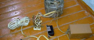
You will have to buy a braided cable in a store and ask them to cut it to the length you need. All that remains for Samodelkin is to cut the ends, mount the outer protection, filling it with lubricants. The shank from a broken drill of a suitable diameter will work as a blank for the mounting unit in the chuck.
As an option, you can take a cable from a car speedometer, as well as a motorcycle gas or clutch control drive as a starting material.
One end of the armored braided wire will need to be welded to the shank of the broken drill using a nut of the appropriate diameter and a welding machine. A drill chuck or a hex adapter is welded to the second end of the cable for quick tool change. Remember that when operating such a drive, you need to hold it not by the rotating cartridge, but by the stationary braid. Such a do-it-yourself device will not only allow you to save money, but also make the drive exactly the length you require. Most factory drives are 25cm or 50cm long.
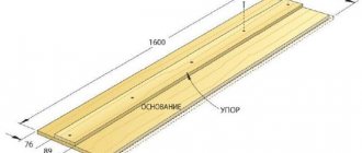
Drawing. The main stages of creating a jointer
Tabletop jointer - drawing
Tabletop jointing machine - drawing (part 2)
A jointing machine, its simplest version without additional functions, can be made quite easily with your own hands. The general progress of work in this case will look like this:
When fastening, glue and clamp are used. The recess should ideally fit the dimensions of the bearing;
After creating the system for turning the electric motor on and off, the machine is ready for use. But in order for your new tool to bring only benefit and joy to work, it is worth using it correctly and safely.
Flexible shaft for engraver
The engraver, or drill, develops high speeds - up to 30 thousand rpm. The device is small-sized and fits comfortably in the hand and is used for operations:
- polishing;
- milling;
- drilling holes of small diameter;
- grinding, etc.
Working as an engraver requires high precision of the master's movements. The effort involved is small, compared to, say, tightening self-tapping screws. The torque is also low. Such devices are used by jewelers and artists who create works that are not inferior to the best examples of wood, stone, and embossing carvers. Engraving is performed on materials such as:
- metal;
- tree;
- stone;
- glass;
- plastics.
Flexible Shaft Engraver
The flexible shaft for the engraver allows the user's manual efforts to be reduced to a minimum, turning many hours of work into an exciting activity.
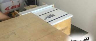
Do-it-yourself cold forging machine from a circular saw shaft
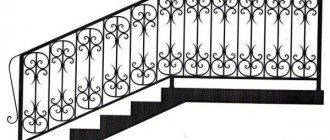
Hello, dear readers and DIYers! Probably some of you are engaged in the manufacture of various metal structures that use curved decorative elements. Most often they are made using conventional forging.
In this article, the author of the YouTube channel “Vladimir Natynchik” will tell you how he made a special machine and jig for making such elements without the need to use a forge.
Almost anyone can repeat this design, but welding work will be required.
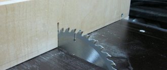
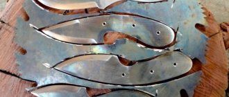
Materials. — Old shaft from a circular saw — Steel profile pipe, sheet, strip, square 10X10 mm — M8 hex screws — Steel roller — Extended nuts, bearings, stud, wood screws — Machine oil.
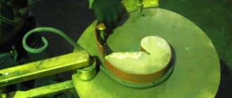
Tools used by the author. — Screwdriver, metal drills, bits — Grinder — Cutting and cleaning discs — Gaffer grip — Square, ruler, marker, wrenches. Manufacturing process. Vladimir accidentally purchased an old circular saw shaft from a scrap metal collection point. He has already removed the belt drive pulleys from it and lubricated the bearings.
He then cleaned the shaft where the welding would be done. A washer will need to be welded to the shaft.
He also made a mark on the shaft at which it would need to be cut. Moreover, this will need to be done so that the washer becomes flush with the axle.
Using a grinder with a cutting disc, and at the same time rotating the shaft, he cuts off the unnecessary part. This results in a fairly flat cut.
Using a semi-automatic welding machine, the washer is welded to the shaft from its rear side.
He drilled two holes in another similar washer and secured the two washers together. Then I made matching holes in the second, already welded washer.
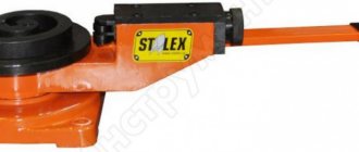
Now you need to make the conductor itself. At the same metal receiving site, he purchased a roller like this, made a cutout in it, and welded a tooth. The result is the central part of the snail.
Two bolts with hexagon heads are fixed in the drilled holes in the washer.
Now, having found the center on the jig and aligning the washer with it, he welds the bolt heads to the back of the jig.
That's all, the jig is ready, and the washer can be removed.
After this, the jig is fixed on the machine flange.
The author also strengthened the lower part of the machine by welding another thick-walled profile 20X40 mm between the holders.
He built a stop like this from a pin, four elongated nuts and bearings, and welded it to the edge of the profile pipe so that it was in the same plane as the jig. The author cut off the excess stud and welded its edge to reinforced nuts.
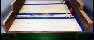
Everything is ready, the machine is secured, and testing can begin. The edge of the steel square is inserted into the center of the snail, and in one revolution of the shaft, a curl like this is obtained.
This is the kind of bending machine the master made. With its help, you can very quickly produce many identical parts with high precision.
All that remains is to make several conductors to perform various shapes. By the way, in one of the articles Andrei Vinnichuk talked about one of the methods for making them.
Good mood, good luck, and interesting ideas to everyone!
The author's video can be found here.
Source
Become the author of the site, publish your own articles, descriptions of homemade products and pay for the text. Read more here.
Shafts for lawn mowers
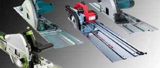
Mechanical scythes with electric and gasoline drives use both flexible and rigid shafts.
Powerful brush cutters, capable of cutting tall, hard and dense grass and even small bushes, use all-metal rigid drives. Such devices are designed for long-term operation and have high torque. They are also large in size and weight and are worn on shoulder straps. The working tool is thick, rigid fishing line or powerful steel knives - two, three or four - bladed.
The flexible drive is used in lightweight, low-power and small-sized trimmers designed for mowing corners after a lawn mower or trimming grass on small lawns. These trimmers are held with one hand, and the flexible shaft is used to mow in the most comfortable position. The cutting element of such devices is a fishing line of small or medium thickness or a lightweight two-bladed knife. If the device is overloaded, the flexible shaft may become twisted. In this case, the rupture usually occurs near the shaft-to-engine attachment point. If you cannot buy a “original shaft”, then you need to select a suitable length from drives in the direction of the braid. Such drives can only rotate in one direction.
Before starting seasonal work and after changing the drive, remove any remaining old lubricant, rinse with gasoline or other solvent, and fill the cavity in the handle with new lubricant. The type of lubricant is specified in the user manual.
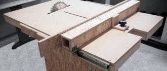
Purpose of the jointer
Design diagram of a jointing machine.
Working with wood can be not only a pleasant hobby, but also an opportunity to provide all the necessary interior items. If you have specialized tools, homemade furniture will not differ much in quality and appearance from its factory-made counterparts. A jointer is one of these tools; it makes it possible to make the surface of wood perfectly smooth and prepare it for gluing, varnishing or applying a decorative design.
A jointer, or jointer, is a tool for finishing lumber of large lengths and widths. Processing is carried out by removing a small (1-2 mm) layer of material using a rotating shaft into which sharp blades made of hardened metal are mounted.
The principle of operation of a jointer is identical to the operation of a plane, with the difference that the jointer is fixed in place, and the material being processed moves. The extended length of the fixture allows it to be used to give a beautiful look to wide, flat surfaces
Speedometer flexible shaft
The flexible shaft transmits torque from the car or motorcycle transmission to the magnetic speedometer sensor. If the speedometer needle, when driving at a constant speed, begins to twitch or goes to the extreme position, it means the cable is faulty. You can replace it yourself. The flexible shaft is selected according to the parts catalog for your car brand. It must match in terms of attachment points and length. If the cable is too long or too short, there is a risk of bending it at too small a radius. This leads to extraneous noise (similar to howling), increased wear and premature failure of the unit.
Drawing. The main stages of creating a jointer
Tabletop jointer - drawing
Tabletop jointing machine - drawing (part 2)
A jointing machine, its simplest version without additional functions, can be made quite easily with your own hands. The general progress of work in this case will look like this:
When fastening, glue and clamp are used. The recess should ideally fit the dimensions of the bearing;
After creating the system for turning the electric motor on and off, the machine is ready for use. But in order for your new tool to bring only benefit and joy to work, it is worth using it correctly and safely.