Worm gears
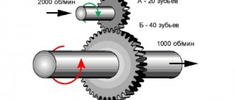
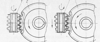
Worm gears are used to transmit rotational motion between shafts, whose axle crossing angle is usually 0 = 90° (Fig. 2.5.1).
Figure 2.5.1. Worm gear: 1 - worm; 2 - the crown of the worm wheel.
In most cases, the drive is a worm, that is, a short screw with a trapezoidal or similar thread. To fit the body of the worm, the crown of the worm wheel has arcuate teeth, which increases the length of the contact lines in the engagement zone. A worm gear is a gear-screw gear, the movement of which is carried out according to the principle of a screw pair.
6.1.2 Scope of application of worm gears
Worm gears are used for small and medium powers, usually not exceeding 100 kW. The use of gears at high power is uneconomical due to the relatively low efficiency and requires special measures to cool the gear in order to avoid strong heating. Worm gears are widely used in hoisting and transport machines, trolleybuses, and especially where high kinematic accuracy is required (dividing devices of machine tools, guidance mechanisms, etc.). To avoid overheating, it is preferable to use worm gears in periodic (rather than continuous) drives.
6.1.3 Advantages of worm gear
1) Smooth and silent operation. 2) Compactness and relatively small weight of the structure. 3) The possibility of large reduction, i.e., obtaining large gear ratios (in some cases in non-power transmissions up to 1000). 4) The possibility of obtaining a self-braking transmission, i.e., allowing the transmission of motion only from the worm to the wheel. Self-braking of the worm gear allows the mechanism to be implemented without a braking device that prevents reverse rotation of the wheel. 5) High kinematic accuracy.
6.1.4 Disadvantages of worm gear
1) Relatively low efficiency due to the sliding of the worm turns along the teeth of the wheel. 2) Significant heat release in the area of engagement of the worm with the wheel. 3) The need to use scarce anti-friction materials for the rims of worm wheels. 4) Increased wear and tendency to seize.
6.1.5 Classification of worm gears
Depending on the shape of the outer surface of the worm (Fig. 2.5.2), gears are available with a cylindrical (a) or globoid (b) worm. The globoid gear has increased efficiency and a higher load-bearing capacity, but is difficult to manufacture and is very sensitive to the axial displacement of the worm caused by wear of the bearings. 1. Depending on the direction of the worm helix line, worm gears come with the right and left direction of the helix line. 2. Depending on the number of turns (thread starts) of the worm, gears are available with a single-turn or multi-turn worm.
Figure 2.5.2. Worm gear diagrams
3. Depending on the location of the worm relative to the wheel (Fig. 2.5.3), gears can be: with lower (a), side (b) and upper (c) worms. Most often, the location of the worm is dictated by the design conditions of the product. The lower worm is usually used at a peripheral speed of the worm u1?5 m/s to avoid losses due to mixing and splashing of oil. 4. Depending on the shape of the helical surface of the thread of a cylindrical worm, gears can be: with Archimedean, convolute and involute worms. Each of them requires a special cutting method.
Figure 2.3.3 Types of worm location
An involute worm is a cylindrical helical gear with an involute profile and a number of teeth equal to the number of turns of the worm. Practice has shown that with the same manufacturing quality, the shape of the worm cutting profile has little effect on the performance of the transmission. The choice of worm cutting profile depends on the manufacturing method and is also related to the shape of the tool for cutting the worm wheel. The most widespread are Archimedean worms (Fig. 2.5.4.
Figure 2.5.4 Archimedes' worm
6.1.6 Basic geometric relationships in a worm gear
The geometric dimensions of the worm and wheel are determined using formulas similar to those for gears. In a worm gear, the calculated axial module of the worm m is equal to the end module of the worm wheel. The values of the calculation modules m are selected from the range: 2; 2.5; 3.15; 4; 5; 6.3; 8; 10; 12.5; 16; 20 mm.
6.1.7 Basic geometric dimensions of the worm (Fig. 2.5.6):
Figure 2.5.6 Geometric parameters of the worm
helix profile angle in the axial section 2a = 40° calculated worm pitch (2.5.1), hence the calculated module (2.5.2), helix stroke (2.5.3), where z1 is the number of worm turns; — the height of the head of the worm coil and the wheel tooth; — the height of the leg of the worm coil and the wheel tooth; - pitch diameter of the worm, i.e., the diameter of a worm cylinder on which the thickness of the coil is equal to the width of the cavity, where q is the number of modules in the pitch diameter of the worm or the worm diameter coefficient. To prevent the worm from being too thin, q is increased as m decreases. Thin worms undergo large deflections during operation, which disrupts the correct engagement. The values of the worm diameter coefficients q are selected from the range: 7.1; 8.0; 9.0; 10.0; 11.2; 12.5; 14.0; 16.0; 18.0; 20.0; 22.4; 25.0. The length of the cut part of the worm depends on the number of turns.
6.1.8 Basic geometric dimensions of the worm wheel
Figure 2.5.7 Geometric parameters of the worm wheel
diameter of the tops of the turns (2.5.4), diameter of the tops of the turns (2.5.5), pitch diameter (2.5.6), diameter of the tops of the teeth (2.5.7), diameter of the wheel valleys (2.5.8) center distance - the main parameter of the worm gear
(2.5.9)
where is the tool displacement coefficient, the largest diameter of the worm wheel
(2.5.10)
The width of the worm wheel rim depends on the number of turns of the worm: GOST recommends combinations of parameters z1, z2, q, m, which ensure, at standard center distances, different gear ratios u..
6.1.9 Structural elements of the worm gear
In most cases, the worm is made as one piece with the shaft to ensure the rigidity of the worm. To save bronze, the gear rim of the worm wheel is made separately from the cast iron or steel disk: 1) a wheel with a pressed rim. This design is used for small wheel diameters in small-scale production (Fig. 2.5.8).
Figure 2.5.8 Wheel with pressed rim
2) a wheel with a screwed rim. This design is used for wheel diameters greater than 400 mm (Fig. 2.5.9)
Figure 2.5.9 Wheel with screwed rim
3) a wheel with a crown cast on a steel center.
This design is used in serial and mass production (Fig. 2.5.10) Figure 2.5.10 wheel with a cast rim Tags; Worm gears, worm shaft, worm gear, bronze worm, screw gear, worm gear, worm screw, worm gear, worm gear worm, gears, worm gear, worm wheel
iSopromat.ru
A worm gear consists of a screw, called a worm, and a worm wheel, which is a type of helical gear.
The axes of the transmission shafts intersect, the angle of intersection is usually 90°.
Figure 41
Unlike a helical gear, the rim of a worm wheel has a concave shape, which helps to somewhat fit the worm and, accordingly, increase the length of the contact line. The worm thread can be single-start or multi-start (2, 4).
Advantages:
- the possibility of obtaining a large gear ratio;
- smooth and quiet operation;
- the possibility of obtaining self-braking (when changing the input).
Flaws:
- relatively low efficiency (with a single-start worm - 0.72; with a two-start worm - 0.8; with a four-start worm - 0.9);
- the need to use expensive anti-friction materials for the wheel;
- increased wear and heat.
Worm gears are classified according to various criteria:
1) in the shape of a worm:
- with a cylindrical worm (Figure 42a);
- with a globoid worm (Figure 42b);
A)
b)
Figure 42
2) according to the shape of the worm coil profile:
- with an Archimedean worm (according to GOST 19036-81 designated -ZA). In the axial section, the tooth profile has the shape of a trapezoid, in the end section - the shape of an Archimedean spiral (Figure 43a);
- with a convolute worm having a rectilinear outline of a coil in a normal section (Figure 43b);
- an involute worm (ZJ), representing a helical gear with a small number of teeth and a large angle of inclination (in the end section the tooth has an involute profile) (Figure 43c).
Figure 43
Due to high sliding speeds, the materials of the worm pair must have anti-friction properties, wear resistance and a reduced tendency to jam.
Worms are made from carbon or alloy steels. The greatest load capacity is possessed by pairs in which the worm turns are heat-treated to high hardness, followed by grinding.
Worm wheels are made mainly of bronze, less often of cast iron.
Tin bronzes of type OF10-1, ONF are considered the best material, but they are expensive and in short supply. Used at high speeds Vs=5...25 m/s. Tin-free bronzes, for example aluminum-iron bronzes such as Br.AZh9-4, have increased mechanical characteristics, but have reduced extreme pressure properties. They are used at Vs<5m/s. Cast iron is used with Vs<2m/s, mainly in manual drives.
Geometry of worm wheel and worm > Course content >
Not Found
| Track. home |
Rice. 64. Worm gear:
a
- scheme;
b -
axial section of the Archimedean worm;
c
- axial section of the worm with concave side surfaces
Main parameters.
The diagram and main elements of the worm gear are shown in Fig.
64. Modules m of
cylindrical worm gears in mm, determined in the axial section of the worm, are given below:
1st row: 1.0; 1.25; 1.6; 2.0; 2.5; 3.15; 4.0; 5.0; 6.3; 8.0; 10.0; 12.5; 16.0; 20.0; 25.0; 2nd row: 1.5; 3.0; 3.5; 6.0; 7.0; 12.0; 3rd row: 1.125; 1.375; 1.75; 2.25; 2.75; 4.5; 9.0; 11.0; 14.0; 18.0; 22.0.
Note
.
The 1st row should be preferred to the 2nd. Modules of the 3rd row can be used in technically justified cases for normalized gearboxes for general mechanical engineering applications. GOST 19672 provides m <
1 mm.
Worm diameter coefficients q:
1st row: 6.3; 8; 10; 12.5; 16.0; 20.0; 25.0; 2nd row: 7.1; 9; 11.2; 14; 18; 22.4. The 1st row should be preferred to the 2nd. According to GOST 19672-74 it is allowed to use q =
7.5 and
q =
12.0.
Worm diameter coefficient q =
25.0 should not be used if possible.
Worms.
GOST 19036-94 applies to orthogonal cylindrical worm gears with worms: Archimedean (ZA), involute (ZL), with a rectilinear coil profile (ZN), formed by a cone (ZK) and a torus (ZT) and establishes the initial worm, the initial producing worm ( cutter) and radial clearances of the worm gear with a module from 1 to 25 mm. The standard does not apply to indexing worm gears and other gears that have special requirements. The shape and dimensions of the turns of the original worm and the original producing worm and the radial clearances of the worm gear in the axial section of these worms, containing the center line of the worm gear, must correspond to those indicated in Fig. 65. The values of the coefficients of the parameters of the turns of the original worm and the original producing worm are given in Table. 126a and 126b.
Rice. 65. Contours of turns of the original worms and the original producing worms:
A
- ZA;
b -
ZL;
ZN; ZK; in —
ZT
Designations of the contours of the turns: _________ - coinciding with the original worm and the original producing worm; — — — — — — the original worm; —·—·—·—·— — the original producing worm. Profile angle values: - in the axial section of the worm turn ZA - α x
;
— in the normal section of the rack tooth coupled with the worm ZL — α n
;
— in the normal section of the worm turn ZN1 — α nT
;
—
in the normal section of the worm cavity ZN2 — α
ns
;
— in the normal section of the helical line of the worm coil ZN3 — α n
; — the producing cone for worms ZK1, ZK2, ZK3 and ZK4 must correspond to 20°; — in the normal section of the worm turn, ZT1 and ZT2 should correspond to 22°.
Note.
It is allowed in technically justified cases (for example, to localize the contact patch) to adjust the profile angle of the original producing worm.
The values of the radius of rounding p k10
of the edge of the producing surface, forming the side surfaces of the turns of the initial producing worm, should be in the range from 0.2
m
to 0.3 m.
126 a. Values of the coefficients of the parameters of the turns of the original worm
| Odds | Designation | Numerical value or formula for worms | ||
| ZA, ZK, ZN | ZL | ZT | ||
| Heights of coil | h1* | 2,0+c1* ; | ||
| Coil head heights | ha1* | 1,0 | ||
| Heights of the coil leg | hf1* | 1,0+c1* ; | ||
| Boundary coil height, not less | hl1* | 2,0 | ||
| Entry depths | hw* | 2,0 | ||
| Radial clearance at the surface of the depressions: | ||||
| worm | c1* | 0,2 | ||
| worm wheel | c2* | 0,2 | ||
| Design coil thickness | s* | 0.5π | 0.45π | 0.35π |
| Radius of curvature of the transition curve | pf1* | 0,3 | 0,2 | |
| Radius of the generating arc of the grinding wheel circle | P0* | — | 4,8-6,0 | |
Notes:
1. It is allowed to change the coefficient of design thickness for worms: ZA, ZL, ZK and ZN in the range from 0.4 to 0.5π;
ZT ranges from 0.3π to 0.38π. 2. In justified cases, it is allowed to change the coefficient of radial clearance at the surface of the worm wheel cavities in the range from 0.15 to 0.3. 3. For involute worms and worms with a pitch angle of at least 26.565°, take 1
= 0.2 cozy.
4. Mandatory thinning of the calculated thickness of the coil of the initial worm ∆ s
in comparison with the calculated thickness of the coil of the initial producing worm is not regulated.
5. The edge of the head of the coil of the original worm is blunted with a radius p k
= 0.05
m
or a chamfer of the appropriate size. 6. The value of the radius coefficient of the generatrix of the arc of the circle of the grinding wheel p0* is taken in the range from 4.8 to 6.0 under the condition that there is no cutting of the worm wheel tooth.
126 b. Values of the coefficients of the parameters of the turns of the initial producing worm
| Odds | Designation | Numerical value or formula for worms | ||
| TA, ZK, ZN | ZL | ZT | ||
| Diameter of the original producing worm | q0* | q (1…1,5) | q (1…1,2) | |
| Module of the original production worm | m0* | m0*=cozy/cosy0 , where y, y0 are the pitch angles of the initial worm and the initial producing worm | ||
| Height of coil, not less | h10* | 2,0+With 1*+ | ||
| Height of the coil head, not less | ha10* | 1,0+With 2* | ||
| Height of the coil leg, not less | hf10* | 1,0+With 1* | ||
| Boundary height of the coil leg, not less | hl10* | 2,0 +With 2* | ||
| Height of the head before the start of rounding, not less | hak10* | 1,0 | ||
| Design coil thickness, not less | s0* | s* cos(y-y0) | ||
| Radius of the generating arc of the grinding wheel circle, no more | P10* | |||
| — | P10*-0.2 | |||
Notes:
1. A larger value of the coefficient
q0*„
is recommended for axial distances
aw
of no more than 80 mm, modules
m
of no more than 2 mm, and the pitch angle of the initial worm no more than 5°.
2. The values of all parameters of the original producing worm are obtained by multiplying the corresponding coefficient by the modulus m
of the original worm. 3. The values of the pitch angle of the initial producing worm are calculated using the formula
where z10
—number of turns of the initial producing worm.
Gears with a single-thread worm cause high friction losses. Worms with z1
= 1 is used for short periods of operation in kinematic (reference) gears, since single-start worms are more accurate than multi-start worms.
The direction of the turns should be set to the right; the left direction of turns is used only in special cases. Worm wheels.
The number of teeth of the worm wheel
z2
is selected depending on the gear ratio and the number of starts of the worm.
In power transmissions, one must strive for a worm lead such that z2
= 30÷70.
When z2
is close to the lower limit, the transmission dimensions are slightly reduced;
but at the same time its efficiency decreases, since it is necessary to install worms with a small number of passes z1, therefore z2
=30÷50 is recommended only for relatively small transmitted powers.
At high powers, one should strive to increase efficiency by increasing z2
to 60÷70.
to use z2 >
80, since in this case the bending strength of the teeth usually becomes decisive (especially for bronzes with high wear resistance).
take z2
< 28 to avoid undercutting the tooth;
with a smaller number of teeth, a displacement of the original contour (tool) is used, as with cylindrical gears. When cutting worm wheels with flying cutters, the number of wheel teeth, if possible, should not contain common factors with the number of worm passes z1.
This is achieved while maintaining the standard parameters of the worm
(z1, m
and
q)
by replacing
z2
=32 with
z2
=31 or 33;
z2
=36 to
z2
=35 or 37, etc.
For these gears, in order not to go beyond the permissible deviations from u
and not to have
x
> 1, it will be necessary to use multi-pass flying cutters (one per run) or
z1
times in the direction of its axis by the amount of the axial step or z1 Rotate the wheel blank once by one angular step.
The number of teeth z2
is not regulated by standards.
Their values are given in table. 127, are selected for cutting wheels with hobs, taking into account achieving, if possible, the same values of gear ratios u
for adjacent center distances.
In table 127 shows combinations of the main parameters aw, u, m, q, z1,
as well as the number of teeth of the worm wheels
z2
, corresponding to the accepted main parameters, the worm displacement coefficients
x
and the actual gear ratios.
Rice. 66. Angle of coverage: a
and
b -
options for crown designs depending on the angle 2δ
The conditional wrap angle 2δ (Fig. 66) is determined by the formula
The grip angle 2δ can be taken for power transmissions 2δ= 90÷120°; for non-reference gears 2δ =
60÷90°;
for non-power reference gears 2δ = 45÷60°. When designing cylindrical worm gears,
you should use the data of GOST 2144-76 (as amended in 1992).
GOST 2144-76 applies to orthogonal cylindrical worm gears for gearboxes, including combined ones (worm-cylindrical, etc.), made in the form of independent units, and establishes: center distances a w
;
nominal values of gear ratios u
nom.
The standard does not apply to worm gears for special-purpose gearboxes and special designs (variable worm pitch, guaranteed self-braking, etc.). Center distances aw
must correspond to the following values:
1st row: 40; 50; 63; 80; 100; 125; 160; 200; 250; 315; 400 mm. 2nd row: 45; 56; 71; 90; 112; 140; 180; 224; 280; 355; 450; 500 mm.
Note.
The values of row 1 should be preferred to the values of row 2.
127. Combination of basic parameters of orthogonal worm gears
| Gear ratios u nom | Options | Center distance аw, mm | |||||||||||||||||
| 40 | 50 | 63 | 80 | 100 | 125 | ||||||||||||||
| 8; 16; 31,5. | z2 : | 32:4 | 32:2 | 32:1 | 32:4 | 32:2 | 32:1 | 32:4 | 32:2 | 32:1 | 32:4 | 32:2 | 32:1 | 32:4 | 32:2 | 32:1 | 32:4 | 32:2 | 32:1 |
| mqx | 2,00 8 0 | 2,50 8 0 | 3,15 8 0 | 4,00 8 0 | 5,00 8 0 | 6,30 8 -0,16 | |||||||||||||
| u | 8 | 16 | 32 | 8 | 16 | 32 | 8 | 16 | 32 | 8 | 16 | 32 | 8 | 16 | 32 | 8 | 16 | 32 | |
| 9,18; 35,5 | z2 : | 36:4 | 36:2 | 36:1 | 36:4 | 36:2 | 36:1 | 36:4 | 36:2 | 36:1 | 36:4 | 36:2 | 36:1 | 36:4 | 36:2 | 36:1 | 36:4 | 36:2 | 36:1 |
| mqx | 1,60 12,5 +0,750 | 2,00 12,5 +0,750 | 2,50 12,5 +0,950 | 3,15 16,0 -0,603 | 4,00 12,5 +0,750 | 5,00 12,5 +0,750 | |||||||||||||
| u | 9 | 18 | 36 | 9 | 18 | 36 | 9 | 18 | 36 | 9 | 18 | 36 | 9 | 18 | 36 | 9 | 18 | 36 | |
| 10; 20;40 | z2 : | 40:4 | 40:2 | 40:1 | 40:4 | 40:2 | 40:1 | 40:4 | 40:2 | 40:1 | 40:4 | 40:2 | 40:1 | 40:4 | 40:2 | 40:1 | 40:4 | 40:2 | 40:1 |
| mq x | 1,60 10 0 | 2,00 10 0 | 2,5 10 +0,2 | 3,15 10 +0,4 | 4,00 10 0 | 5,00 10 0 | |||||||||||||
| u | 10 | 20 | 40 | 10 | 20 | 40 | 10 | 20 | 40 | 10 | 20 | 40 | 10 | 20 | 40 | 10 | 20 | 40 | |
| 11,2; 22,4; 45 | z2 : | 46:4 | 46:2 | 46:1 | 46:4 | 46:2 | 46:1 | 46:4 | 46:2 | 46:1 | 46:4 | 46:2 | 46:1 | 46:4 | 46:2 | 46:1 | 46:4 | 46:2 | 46:1 |
| mq x | 1,25 16 +1,00 | 1,60 16 +0,25 | 2,00 16 +0,50 | 2,50 16 +1,00 | 3,15 16 +0,75 | 4,00 16 +0,25 | |||||||||||||
| u | 11,5 | 23 | 46,0 | 11,5 | 23 | 46,0 | 11,5 | 23 | 46,0 | 11,5 | 23 | 46,0 | 11,5 | 23 | 46,0 | 11,5 | 23 | 46,0 | |
| 12,5; 25;50 | z2 : | 50:4 | 50:2 | 50:1 | 50:4 | 50:2 | 50:1 | 50:4 | 50:2 | 50:1 | 50:4 | 50:2 | 50:1 | 50:4 | 50:2 | 50:1 | 50:4 | 50:2 | 50:1 |
| m q x | 1,25 12,5 +0,750 | 1,60 12,5 0 | 2,00 12,5 +0,250 | 2,50 12,5 +0,750 | 3,15 12,5 +0,496 | 4.00 12,5 0 | |||||||||||||
| u | 12,5 | 25 | 50,0 | 12,5 | 25 | 50,0 | 12,5 | 25 | 50,0 | 12,5 | 25 | 50,0 | 12,5 | 25 | 50,0 | 12,5 | 25 | 50,0 | |
| 14; 28; 56 | z2 : | 58:4 | 58:2 | 58:1 | 58:4 | 58:2 | 58:1 | 58:4 | 58:2 | 58:1 | 58:4 | 58:2 | 58:1 | 58:4 | 58:2 | 58:1 | 58:4 | 58:2 | 58:1 |
| mqx | 1,00 20 +1,000 | 1,25 20 +1,000 | 1,60 20 +0,375 | 2,00 20 +1,000 | 2,50 20 +1,000 | 3,15 20 +0,682 | |||||||||||||
| u | 14,5 | 29,0 | 58,0 | 14,5 | 29,0 | 58,0 | 14,5 | 29,0 | 58,0 | 14,5 | 29,0 | 58,0 | 14,5 | 29,0 | 58,0 | 14,5 | 29,0 | 58,0 | |
| 63 | z2 : | 63:1 | 63:1 | 63:1 | 63:1 | 63:1 | 63:1 | ||||||||||||
| m q x | 1,00 16 0,500 | 1,25 16 0,500 | 1,60 16 -0,125 | 2,50 16 +0,500 | 2,50 16 +0,500 | 3,15 16 +0,180 | |||||||||||||
| u | 63 | 63 | 63 | 63 | 63 | 63 | |||||||||||||
| 80 | z2 : z1 | — | — | — | 80:1 | 80:1 | 80:1 | ||||||||||||
| m q x | 1,6 20 0 | 2,0 20 0 | 2,5 20 0 | ||||||||||||||||
| u | 80 | 80 | 80 | ||||||||||||||||
| Gear ratios u nom | Options | Center distance аw, mm | |||||||||||||||||
| 140 | 160 | 180 | 200 | 225 | 250 | ||||||||||||||
| 8; 16; 31,5 | z2 : | 32:4 | 32:2 | 32:1 | 32:4 | 32:2 | 32:1 | 32:4 | 32:2 | 32:1 | 32:4 | 32:2 | 32:1 | 32:4 | 32:2 | 32:1 | 32:4 | 32:2 | 32:1 |
| m q x | 6,3 12,5 -0,03 | 8,0 8,0 0 | 8,0 12,5 +0,25 | 10,0 8,0 0 | 10,0 12,5 +0,25 | 12,5 8,0 0 | |||||||||||||
| u | 8 | 16 | 32 | 8 | 16 | 32 | 8 | 16 | 32 | 8 | 16 | 32 | 8 | 16 | 32 | 8 | 16 | 32 | |
| 9; 18; 35,5 | z2 : | 36:4 | 36:2 | 36:1 | 36:4 | 36:2 | 36:1 | 36:4 | 36:2 | 36:1 | 36:4 | 36:2 | 36:1 | 36:4 | 36:2 | 36:1 | 36:4 | 36:2 | 36:1 |
| m q x | 6,3 8,0 -0,222 | 6,3 14,0 +0,397 | 8,0 8,0 +0,500 | 8,0 12,5 +0,750 | 10,0 8,0 +0,500 | 10,0 12,5 +0,750 | |||||||||||||
| u | 9 | 18 | 36 | 9 | 18 | 36 | 9 | 18 | 36 | 9 | 18 | 36 | 9 | 18 | 36 | 9 | 18 | 36 | |
| 10; 20;40 | z2 : | 40:4 | 40:2 | 40:1 | 40:4 | 40:2 | 40:1 | 40:4 | 40:2 | 40:1 | 40:4 | 40:2 | 40:1 | 40:4 | 40:2 | 40:1 | 40:4 | 40:2 | 40:1 |
| m q x | 5,0 16 0 | 6,3 10 +0,397 | 6,3 16 +0,571 | 8,0 10 0 | 8,00 16 +0,125 | 10,0 10 0 | |||||||||||||
| u | 10 | 20 | 40 | 10 | 20 | 40 | 10 | 20 | 40 | 10 | 20 | 40 | 10 | 20 | 40 | 10 | 20 | 40 | |
| 11,2; 22,4; 45 | z2 : | 46:4 | 46:2 | 46:1 | 46:4 | 46:2 | 46:1 | 46:4 | 46:2 | 46:1 | 46:4 | 46:2 | 46:1 | 46:4 | 46:2 | 46:1 | 46:4 | 46:2 | 46:1 |
| m q x | 5,0 16 0 | 5,0 16 +1,000 | 6.3 10 +0,571 | 6,3 16 +0,750 | 8,0 10 +0,125 | 8,0 16 +0,250 | |||||||||||||
| u | 11,5 | 23,0 | 46,0 | 11,5 | 23,0 | 46,0 | 11,5 | 23,0 | 46,0 | 11,5 | 23,0 | 46,0 | 11,5 | 23 | 46,0 | 11,5 | 23,0 | 46,0 | |
| 12,5; 25; 50 | z2 : | 50:4 | 50:2 | 50:1 | 50:4 | 50:2 | 50:1 | 50:4 | 50:2 | 50:1 | 50:4 | 50:2 | 50:1 | 50:4 | 50:2 | 50:1 | 50:4 | 50:2 | 50:1 |
| m q x | 4,0 20,0 0 | 5,0 12,5 +0,750 | 5,0 20,0 +0,100 | 6,3 12,5 +0,496 | 6,3 20,0 +0,710 | 8,0 12,5 0 | |||||||||||||
| u | 12,5 | 25,0 | 50,0 | 12,5 | 25,0 | 50,0 | 12,5 | 25,0 | 50,0 | 12,5 | 25,0 | 50,0 | 12,5 | 25,0 | 50,0 | 12,5 | 25,0 | 50,0 | |
| 14; 28; 56 | z2 : z1 | 58:4 | 58:2 | 58:1 | 58:4 | 58:2 | 58:1 | 58:4 | 58:2 | 58:1 | 58:4 | 58:2 | 58:1 | 58:4 | 58:2 | 58:1 | 58:4 | 58:2 | 58:1 |
| m q x | 4,0 12,5 -0,250 | 4,0 20,0 +1,00 | 5,0 12,5 +0,750 | 5,0 20 +1,000 | 6,3 12,5 +0,464 | 6,3 20,0 +0,682 | |||||||||||||
| u | 14,5 | 29,0 | 58,0 | 14,5 | 29,0 | 58,0 | 14,5 | 29,0 | 58,0 | 14,5 | 29,0 | 58,0 | 14,5 | 29,0 | 58,0 | 14,5 | 29,0 | 58,0 | |
| 63 | z2 : z1 | — | 63:1 | 63:1 | 63:1 | 63:1 | 63:1 | ||||||||||||
| m q x | 4,0 16,0 +0,500 | 5,0 12,5 -0,750 | 5,0 16,0 +0,500 | 6,3 12,5 -1,000 | 6,3 16,0 +0,182 | ||||||||||||||
| u | 63 | 63 | 63 | 63 | 63 | ||||||||||||||
| 71 | z2 : z1 | 73:1 | — | 73:1 | — | 73:1 | — | ||||||||||||
| m q x | 3,15 16 -0,56 | 4,00 16 +0,50 | 5,00 16 +0,50 | ||||||||||||||||
| u | 73 | 73 | 73 | ||||||||||||||||
| 80 | z2 : z1 | — | 80:1 | — | 80:1 | — | 80:1 | ||||||||||||
| m q x | 3,15 20 +0,794 | 4,00 20 0 | 5,00 20 0 | ||||||||||||||||
| u | 80 | 80 | 80 | ||||||||||||||||
| Gear ratios u nom | Options | Center distance аw , mm | |||||||||||||||||
| 280 | 315 | 355 | 400 | 450 | 500 | ||||||||||||||
| 8; 16; 31,5 | z2 : | 32:4 | 32:2 | 32:1 | 32:4 | 32:2 | 32:1 | 32:4 | 32:2 | 32:1 | 32:4 | 32:2 | 32:1 | 32:4 | 32:2 | 32:1 | 32:4 | 32:2 | 32:1 |
| m q x | 12,5 12,5 +0,150 | 16,0 8,0 -0,300 | 16,0 12,5 -0,063 | 20,0 8,0 0 | — | — | |||||||||||||
| u | 8 | 16 | 32 | 8 | 16 | 32 | 8 | 16 | 32 | 8 | 16 | 32 | |||||||
| 9; 18; 35,5 | z2 : | 36:4 | 36:2 | 36:1 | 36:4 | 36:2 | 36:1 | 36:4 | 36:2 | 36:1 | 36:4 | 36:2 | 36:1 | 36:4 | 36:2 | 36:1 | 36:4 | 36:2 | 36:1 |
| m q x | 12,5 8,0 +0,400 | 12,5 12,5 +0,950 | 16,0 8,0 +0,187 | 16,0 12,5 +0,750 | 20,0 8,0 +0,500 | — | |||||||||||||
| u | 9 | 18 | 36 | 9 | 18 | 36 | 9 | 18 | 36 | 9 | 18 | 36 | 9 | 18 | 36 | ||||
| 10; 20; 40 | z2 : | 40:4 | 40:2 | 40:1 | 40:4 | 40:2 | 40:1 | 40:4 | 40:2 | 40:1 | 40:4 | 40:2 | 40:1 | 40:4 | 40:2 | 40:1 | 40:4 | 40:2 | 40:1 |
| m q x | 10,0 16 0 | 12,5 10 +0,200 | 12,5 16 +0,400 | 16,0 10 0 | 16,0 16 +0,125 | 20,0 10 0 | |||||||||||||
| u | 10 | 20 | 40 | 10 | 20 | 40 | 10 | 20 | 40 | 10 | 20 | 40 | 10 | 20 | 40 | 10 | 20 | 40 | |
| 11,2; 22,4; 45 | z2 : z1 | 46:4 | 46:2 | 46:1 | 46:4 | 46:2 | 46:1 | 46:4 | 46:2 | 46:1 | 46:4 | 46:2 | 46:1 | 46:4 | 46:2 | 46:1 | 46:4 | 46:2 | 46:1 |
| m q x | 10,0 10 0 | 10,0 16 +0,500 | 12,5 10 +0,400 | 12,5 16 +1,000 | 16,0 10 +0,125 | 16,0 16 +0,250 | |||||||||||||
| u | 11,5 | 23,0 | 46,0 | 11,5 | 23,0 | 46,0 | 11,5 | 23,0 | 46,0 | 11,5 | 23,0 | 46,0 | 11,5 | 23 | 46,0 | 11,5 | 23,0 | 46,0 | |
| 12,5; 25; 50 | z2 : z1 | 50:4 | 50:2 | 50:1 | 50:4 | 50:2 | 50:1 | 50:4 | 50:2 | 50:1 | 50:4 | 50:2 | 50:1 | 50:4 | 50:2 | 50:1 | 50:4 | 50:2 | 50:1 |
| m q x | 8,0 20,0 0 | 10,0 12,5 +0,25 | 10,0 20,0 +0,50 | 12,5 12,5 +0,75 | 2,5 20,0 +1,00 | 16,0 12,5 0 | |||||||||||||
| u | 12,5 | 25,0 | 50,0 | 12,5 | 25,0 | 50,0 | 12,5 | 25,0 | 50,0 | 12,5 | 25,0 | 50,0 | 12,5 | 25,0 | 50,0 | 12,5 | 25,0 | 50,0 | |
| 14; 28; 56 | z2 : z1 | 58:4 | 58:2 | 58:1 | 58:4 | 58:2 | 58:1 | 58:4 | 58:2 | 58:1 | 58:4 | 58:2 | 58:1 | 58:4 | 58:2 | 58:1 | 58:4 | 58:2 | 58:1 |
| m q x | 8,0 12,5 -0,250 | 8,0 20,0 +0,375 | 10,0 12,5 +0,250 | 10,0 20,0 +1,000 | 12,5 12,5 +0,750 | 12,5 20,0 +1,000 | |||||||||||||
| u | 14,5 | 29,0 | 58,0 | 14,5 | 29,0 | 58,0 | 14,5 | 29,0 | 58,0 | 14,5 | 29,0 | 58,0 | 14,5 | 29,0 | 58,0 | 14,5 | 29,0 | 58,0 | |
| 63 | z2 : z1 | — | 63:1 | — | 63:1 | 61:1 | 63:1 | ||||||||||||
| m q x | 8,0 16,0 -0,125 | 10,0 16,0 +0,500 | 12,5 12,5 -0,750 | 12,5 16,0 +0,500 | |||||||||||||||
| u | 63 | 63 | 61 | 63 | |||||||||||||||
| 71 | z2 : z1 | 73:1 | — | 73:1 | — | 73:1 | — | ||||||||||||
| m q x | 6,3 16 -0,056 | 8,00 16 -0,125 | 10,0 16 +0,500 | ||||||||||||||||
| u | 73 | 73 | 73 | ||||||||||||||||
| 80 | z2 : z1 | — | 80:1 | — | 80:1 | — | 80:1 | ||||||||||||
| m q x | 6,3 20 0 | 6,3 20 0 | 10,0 20 0 | ||||||||||||||||
| u | 80 | 80 | 80 | ||||||||||||||||
Nominal gear ratios must correspond to the following values: 1st row: 8; 10; 12.5; 16; 20; 25; 31.5; 40; 50; 63; 80; 100. 2nd row: 9; 11.2; 14; 18; 22.4; 28; 35.5; 45; 56; 71; 90.
Notes:
1. The values of row 1 should be preferred to the values of row 2. 2. Gear ratios 90 and 100 are not recommended. The actual values of the gear ratios should not differ from the nominal values by more than 4%.
Note.
For normalized gearboxes for general machine-building applications, in technically justified cases, deviation of the actual values of gear ratios from nominal to 6.3% is allowed. Gear worms, with the exception of cases determined by the kinematics of the drive, must have a helical line in the right direction.
GEOMETRICAL CALCULATION OF WORM GEAR
Calculation of the geometry of a worm gear according to GOST 19650-74 provides for gears with a crossing angle of the worm and wheel axes equal to 90°, and an initial worm according to GOST 19036-94. Formulas and an example of calculating a worm gear are given in Table 128.
128. Formulas and example of calculating a cylindrical worm gear
| Parameters and notations | Formulas and instructions | Numeric values | |
| Initial data | |||
| Module m Worm diameter coefficient | In this example ZL | 6.3 mm 10 2 — | |
| Initial worm according to GOST 19036-94 | Profile angle αx or αn, αnТ, αnS, α0 Height coefficient h* Head height coefficient ha* , Design thickness coefficient s* Transition curve radius of curvature coefficient ρf* | In this example αn | 20° 2+0.2 cos y 1,0 1,571 0,3 |
| Center distance aw, Worm displacement coefficient | 160 mm - 20 | ||
| Notes: 1. Center distance | |||
| Calculation of geometric parameters | |||
| Number of worm wheel teeth Z 2 | In general: z 2= | We accept z 2 = 39. Adjusted value | |
| Parameters and notations | Formulas and instructions | Numeric values | |
| Worm displacement coefficient x | It is recommended to take the worm displacement coefficient within 1 ≥ x ≤-1 | 0,897 | |
| Center distance (if X included in the source data) | aw= 0.5( z 2+ q +2 x ) m | — | |
| Calculation of the diameters of the worm and worm wheel | |||
| Pitch diameter: worm | d1=qm= 10·6.3 d2=z2m= 39·6.3 | 63 mm 245.7 mm | |
| Initial worm diameter dw1 Pitch angle y Initial elevation angle yw Main elevation angle yb | dw1= ( q +2x) m =(10+2·0,897)·6,3 cozy b=cos α Defined for ZL worm | 74.30 mm y=11°19‘ yw=9°37‘ yb=22°52‘ | |
| Main worm diameter db Worm coil height h1 Worm head height ha1 | Defined for ZL worm h1=hm*= (2+0.2cos11°19 | 29.89 mm 13.84 mm 6.3 mm | |
| Top diameter | worm turns dа1 wheel teeth dа2 | dа1 = d1+2ha*m= 63+2·1·6,3 da2=d2 +2( | 75.6 mm 269.6 mm |
| Parameters and notations | Formulas and instructions | Numerical values | |
| The largest diameter of the worm wheel is dае2 | 279.05 mm We accept dae2 =279 mm | ||
| Calculation of dimensions characterizing the shape of the cut part of the worm and the rim of the worm wheel | |||
| Radius of curvature of the worm transition curve Rf1 Length of the uncut part of the worm | рf1 = рf*m =0,3·6,3 Determined by the formulas in table. 129 b1 ≥(12 + 0.1 | 1.9 mm We accept for ¦ ground i worm b1 =125 mm | |
| Worm wheel width b2 | Recommended to take: b2 ≤0.75 b2 ≤0.67 In this example b2 = 0,75 | 56.7 mm; accept b2 =55 mm ; | |
| Calculation of dimensions to control the relative position of the worm coil profiles | |||
| Estimated worm pitch p1 Stroke pz1 Pitch thickness along the chord of the worm turn sa1 | p1 = π m =3,1416·6,3 рz1 = | 19.792 mm 39.584 mm 9.71 mm | |
| Height to chord of turn ha1 | 6.314 mm | ||
| Parameters and notations | Formulas and instructions | Numerical values | |
| Diameter of measuring rollers D | D ≥1,67 It is recommended to take the value D equal to the nearest larger roller diameter according to GOST 2475-88 (Chapter IX, Table 38) | 10.5 mm Accept D = 10.95 mm | |
| Worm size by rollers M1 | For ZL worms α=20° | 79.51 mm | |
129. Calculation of the length of the cut part of the worm b1
| Offset factor x | Calculation formulas for z 1, equal | |
| 1 and 2 | 4 | |
| -1,0 | b1 ≥(10.5+ | b1 ≥(10.5+ |
| -0,5 | b1 ≥(8+0.06 | b1 ≥(9.5+0.09 |
| 0 | b1 ≥(11+0.06 | b1 ≥(12.5+0.09 |
| +0,5 | b1 ≥(11+0.1 | b1 ≥(12.5+0.1 |
| +1,0 | b1 ≥(12+0.1 | b1 ≥(13+0.1 |
| Notes: 1. For an intermediate value of the displacement factor x, the length &i is calculated from the nearest limit | ||
404 Not Found
The requested URL /bottom.php was not found on this server.
Additionally, a 404 Not Found error was encountered while trying to use an ErrorDocument to handle the request.
Advantages:
- smooth engagement and quiet operation of the structure;
- compactness and relatively low weight of the structure;
- possibility of large reduction, i.e. obtaining large gear ratios (in some cases in non-power transmissions up to 1000);
- the possibility of obtaining a self-braking transmission, i.e. allowing the transfer of motion only from the worm to the wheel. The self-braking of the worm gear allows the mechanism to be implemented without a braking device that prevents reverse rotation of the wheel.
Application
Worm gears are used for small and medium powers, usually not exceeding 50 kW. The use of gears at high power is uneconomical due to the relatively low efficiency. and requires special measures to cool the transmission to avoid excessive heating.
Worm gears are widely used in devices for replacing plate cylinders, in lifting mechanisms for installing and removing the plate cylinder, in the mechanism for axial movement of the rolling cylinder and regulating its stroke, in various types of inking machines, etc.
When designing gears consisting of gear and worm pairs, it is recommended to use the worm pair as a high-speed stage, since by increasing the peripheral speed of the worm, more favorable conditions are created for the formation of a stable oil wedge in the worm gearing and, consequently, friction losses are reduced.
To avoid overheating, it is preferable to use worm gears in periodic (rather than continuous) drives.