Mechanical gears
Gears are understood as mechanical devices that allow the transfer of energy from a machine-engine to a machine-implement. In modern machines, energy transmission is carried out by mechanical, hydraulic and pneumatic transmissions: In all mechanical transmissions, the shaft and parts mounted on it (gears, pulleys, etc.) transmitting torque are called driving, and the parts driven by the driving ,—followers. Between the drive and driven shafts in multi-stage transmissions there are intermediate shafts.
Transmissions are classified according to two criteria: 1) according to the method of transmitting motion: friction - friction, belt, rope; gearing - gear, worm, screw, chain; 2) according to the method of connecting the driving and driven links: direct contact - friction, gear, worm, screw; with additional connection - belt, chain.
Transmissions are performed with both constant and variable gear ratios, and the change in gear ratio can be stepped or stepless.
Friction transmissions consist of two rollers (wheels) of cylindrical or conical shape, mounted on shafts and pressed against each other by external force. The movement is transmitted by the frictional force that arises between the rollers.
Belt drives are used mainly in cases where the shafts are located at a considerable distance from each other and when the transmission is not required to have a strictly constant gear ratio. Belt drives are one of the oldest types of mechanical transmissions and are used in almost all branches of mechanical engineering.
The transmission consists of two pulleys mounted on shafts and an endless belt stretched over the pulleys.
Depending on the shape of the cross-section of the belt, transmissions are distinguished: flat belt, V-belt and round belt.
To ensure the required belt tension, special tensioning devices are usually introduced into the transmission (the electric motor is placed on movable guides or hinged, etc.).
The most common type of mechanical transmission is gear transmission. The main advantages of these gears are high efficiency (up to 0.98), compactness compared to friction and belt gears, constant gear ratio, and the ability to transmit high powers.
Gears and wheels are classified according to the following main characteristics: 1) according to the relative position of the wheel axes; there are cylindrical ones with parallel axes, and the engagement can be either external or internal (Fig. 3.11); conical when they intersect (Fig. 3.12); bevel gear with intersecting axes (hypoid); rack and pinion gears, which serve to convert the rotational motion of a gear into the translational motion of a rack, and vice versa;
Fig: 3.11. Cylindrical gears.
2) by the location of the teeth relative to the generatrix of the wheels; distinguish between straight teeth (Fig. 3.11, a and Fig. 3.12, a), helical (Fig. 3.11,6 and Fig. 3.12,6), chevron (Fig. 3.11, c) and with curved teeth (Fig. 3.12, c) . When switching from spur gears to non-spur gears, smooth operation increases, wear and noise decreases. Based on the shape of the teeth profile, involute, cycloidal and circular gearings are distinguished.
Rice. 3.12. Bevel gears.
Worm gears are used to transmit rotational motion between shafts whose axes are crossed.
The worm gear (Fig. 3.13) consists of a rotating screw 1, called a worm, and a worm wheel 2, which has teeth on its rim that engage with the turns of the worm. The driving link of the transmission is usually a worm, one-, two- or four-thread.
Rice. 3.13. Worm-gear.
In addition to gear and worm gears, mechanical gears also include chain and screw drives.
Chain drives are used when it is necessary to transmit rotational motion without slipping between shafts located at a considerable distance from each other (up to 8 m).
The chain drive is based on the engagement of the traction element in the form of an endless closed chain with sprockets, which are gears with teeth of a special profile. The chain can span two or more sprockets.
The efficiency of the chain transmission is relatively high and amounts to 0.96–0.98.
The most common are bush drive (Fig. 3.14), roller, toothed and shaped link chains.
Rice. 3.14. Drive chains.
Screw gears (screw-nut) serve to convert rotational motion into translational motion, and in some cases vice versa.
Advantages of screw gears: ease of obtaining slow motion with a large gain in strength; simplicity of design and manufacturing technology; the ability to absorb heavy loads and carry out movements with great accuracy. The disadvantage of such gears is high friction, which causes increased wear and low efficiency.
Rotating parts in machines and mechanisms are mounted on axles and shafts. Axes can be rotating or stationary, and they do not transmit torque and, therefore, experience only bending deformation. Shafts, unlike axles, serve to transmit torque and, under the influence of loads applied to them, experience torsional and bending deformations.
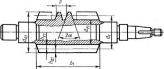
The supporting surfaces of axles and shafts are called axles. The end pins are called tenons, and the intermediate ones are called necks (Fig. 3.15). The end part of the shaft, designed to transmit the axial load to the fixed support, is called the fifth.
Rice. 3.15. Basic elements of axles and shafts.
The shafts and rotating axles are supported by bearings and thrust bearings. Bearings absorb radial and axial loads and transfer them to the body or frame of the machine. With the help of bearings, shafts and axles are installed in a certain position relative to other parts of the machine. The thrust bearings absorb axial loads, mainly vertical.
Bearings and thrust bearings are divided into sliding bearings and heated bearings based on the type of friction; in the latter, sliding friction is replaced by rolling friction by using intermediate rolling bodies in the form of balls or rollers.
Sliding bearings usually consist of two main elements: a housing and a liner made of antifriction material. These bearings are simple and reliable in operation, but have relatively low efficiency and significant lubricant consumption.
Sliding bearings can be divided into two groups: solid (or blind) and detachable. A split bearing (Fig. 3.16) consists of a housing 1, a cover 4, bolts or studs 3 that fasten the cover to the housing, and a liner 2, consisting of two halves. Thick or liquid lubricant is supplied through the hole in cover 4. The wear of the liners is compensated by tightening the top cover.
Rice. 3.16. Split plain bearing.
Rolling bearings are standardized and produced by industry in mass quantities in a wide range of standard sizes with an outer diameter from 1.5 mm to 2.6 m and a weight from 0.5 g to 3.5 tons.
Rolling bearings (Fig. 3.17) in most cases consist of two rings 1 (outer) and 2 (inner), rolling elements 4 (balls or rollers) and a cage 3 that holds the rolling elements at a distance from each other.
Rice. 3.17. Rolling bearing (section). Rice. 3.18. Angular contact roller (a) and thrust ball (b) bearings.
These bearings, compared to plain bearings, have lower frictional torques (i.e., higher efficiency), relatively low heating, low lubricant consumption and small width. Disadvantages are sensitivity to impact loads and relatively large radial dimensions.
Depending on the shape of the rolling elements, bearings are divided into ball and roller. There are rollers: short and long cylindrical, conical, barrel-shaped and needle-shaped.
Based on the type of load they absorb, bearings are divided into radial (Fig. 3.17), angular contact (Fig. 3.18,a) and thrust (Fig. 3.18,6).
Depending on the number of rows of rolling elements, bearings can be single-row or double-row.
Couplings are devices designed to connect shafts to each other or to other parts rotating on shafts (gears, sprockets, pulleys, etc.).
By design, couplings can be divided into three main groups: permanent, preventing the shafts from disengaging (disconnecting) during machine operation; coupling, allowing you to engage and disengage the shafts both during a stop and during operation (on the move); safety, coupling and disengaging shafts automatically when the operating mode of the machine changes.
Permanent couplings include: blind couplings, used with strict alignment of the shafts being connected; compensating, allowing displacement and distortions of the axes of the connected shafts; elastic, softening shocks and impacts.
The most common blind couplings are: longitudinally folded and transversely folded (Fig. 3.19).
Rice. 3.19. Blind cross-coupling. Rice. 3.20. Disc friction clutch.
Coupled controlled couplings are divided into cam and gear couplings, based on the engagement of the coupling halves, and friction couplings, which use friction to smoothly engage the drive and driven shafts under load. According to the shape and number of working surfaces, friction clutches are divided into disk, multi-disc and conical.
The simplest disc friction clutch (Fig. 3.20) consists of a coupling half 2, fixedly mounted on the shaft, and a coupling half 1, which can be shifted in the axial direction using a control mechanism. To engage the clutch, a force Q is applied to the movable coupling half, and a frictional moment arises on the end surfaces of the contact of the coupling halves, rotating the driven coupling half.
Any friction clutch, adjusted to transmit the maximum torque for the machine, serves as a safety clutch. There are other designs of safety couplings, for example with shear pins, etc.