General definition
The value of the gear ratio for kinematic schemes is calculated using a standard mathematical expression. The result is obtained by performing a mathematical operation of dividing the angular velocity of the drive shaft or gear by the same parameter of the driven shaft. Instead of these values, the ratio of their rotational speeds is used.
Modern kinematic schemes are implemented using the following mechanical connections:
- with gearing (in different variations);
- worm;
- friction connections;
- using chains;
- using special belts;
- planetary connections.
The transmission of rotation is based on two physical principles: using friction, using gearing mechanisms. Depending on the task being solved, mechanisms are manufactured with deceleration and acceleration. The former are called reducers, the latter - multipliers. Both varieties are single-stage, two-stage, and multi-stage.
The spatial arrangement of the axes determines the following types of mechanisms:
- parallel (in them both shafts are located parallel to each other);
- intersecting (engagement occurs through intersection);
- intersecting mechanisms (their shafts engage in cross engagement).
All types of mechanisms can slow down or speed up movement. The most frequent use of decelerating structures is explained by the higher speed of the motors used and the need to increase the power of the output element of the kinematic circuit.
Depending on the speed ratio, the question arises: can the gear ratio be negative? This coefficient is the ratio of quantities that have only positive values. It cannot be negative. Depending on the ratio of the numerator to the denominator, the result will be more than one or less. In the first case, it is valid for reducers, in the second for multipliers.
The gear ratio table is a summary document. It contains the values of the main technical characteristics of all types of kinematic connections.
In the summary table you can find the dependence of the gear ratio on the permissible power transmitted by a specific type of connection.
General provisions
Modern car enthusiasts must take into account that accurate gear ratio readings for all kinetic schemes can only be calculated according to a standard mathematical expression. In this case, the final result should be obtained by carrying out a specific operation of dividing the angular velocity of the drive gear by the same value of the driven gear. It is noteworthy that instead of such parameters, the ratio of the current rotation speeds of these elements is most often used.
Gear
This is a mechanical connection of two or more rotating shafts using special wheels, on the surface of which teeth are machined. This type is divided according to the following characteristics:
- shape and type of teeth;
- relative location of the shafts in the housing;
- calculated wheel speed;
- degree of protection from external influences.
The transmission ratio of the gear train plays an important role in understanding the operation of the entire mechanism. It is calculated using the classic expression. It is found by substituting various parameters. For example, counting the number of teeth produced on the drive and driven wheels. The formula allows you to obtain results with a high degree of accuracy:
Where i12 is the gear ratio from link 1 to link 2 (link 1 is driving, link 2 is driven; d1, d2 are the diameters of the links; z1, z2 are the number of teeth of the links (if any); M1, M2 are the torques of the links; ω1, ω2 are the angular velocities of the links; n1, n2 are the rotation frequencies of the links.
To a greater extent, it depends on the number of teeth located on the gear. A significant advantage of a gear connection is the constancy of the calculated and actual gear ratio. It is due to the absence of the slipping effect.
The number of gears used and the number of gears has a significant influence on the value of this indicator.
For a cylindrical gear, this parameter, in addition to the above parameters, depends on the center distance. Cylindrical gears are common in various units of cars and trucks, tractors, and agricultural machinery. They are actively used in transmissions.
The gear transmission has the highest power transmission coefficient. It is capable of delivering power up to 4500 kW with a gear ratio reaching 6.3.
Conical-type gear structures have become widespread. They have orthogonal articulation. Calculation of a bevel gear involves taking into account such parameters as: pitch diameters, cone angles, number of teeth.
To obtain translational motion, a rack and pinion connection is used. Structurally, it consists of a gear and a rack with applied teeth. For a rack and pinion transmission, the diameter of the circle and the number of teeth on the wheel and the number of teeth located on the rack are taken into account.
Some subtleties
The gear ratio is determined by the presence of at least two gears (gears) that are in mesh with each other. This coupling is called a gear drive.
The easiest way to calculate the gear ratio is to count the number of teeth on each of the existing wheels, and then divide the number of teeth on the driven gear by the number of wheels on the drive gear. This rational number will be the gear ratio.
It is important to keep in mind that in the case of determining the gear ratio in a gear train that has several gears, it is again necessary to divide the number of teeth of the drive wheel by the number of the driven wheel. In this case, the parameters of the intermediate gears are not taken into account.
Planetary gear
The so-called planetary kinematic scheme is widely used. It is a mechanism designed to transmit and transform rotational motion. For this purpose, gears located on a moving axis are used. The structural elements are: central gears mounted on fixed axles, side gears (located on moving axes). To ensure the best effect, planetary mechanisms are manufactured on parallel axes.
The maximum gear ratio reaches 9 units.
The efficiency is quite high. Its value is close to 0.98. The most common are designs that use several satellites. They are placed in angular steps of equal size.
Such designs are made with a constant or variable gear ratio. Some of them have the ability to adjust this parameter. They are designed to be reversible and irreversible. In reversible samples, movement in the forward and reverse directions is provided. In irreversible structures such movement is impossible. The change in gear ratio can be stepped or stepless. A striking representative of the first unit is the car’s manual transmission. The second option is used in CVTs.
The considered gear ratios are calculated at the design stage of the unit when choosing a kinematic diagram. With their help, the type of connection is selected and the effectiveness is determined. The reliability of the entire mechanism is assessed.
Selection of intermediate gear ratios
There are two ways to select gear ratios for 2nd and 3rd gears. The first is to determine the transmission breakdown indicator q:
Here: – maximum speed in top gear; – maximum speed in 1st gear; m – serial number of the highest gear. In this case, the remaining gear ratios are determined from the breakdown indicator:
In this case, the gears are evenly distributed over the range, that is, for all gears
Let's see how the gears compare in existing vehicles. The manual “Traction calculation of a car” shows the gear ratios of the gearboxes of various cars. I processed them statistically, determining the average breakdown values for different groups of cars and motorcycles.
Table. Gear breakdown indicators for various vehicles.
In general, it can be seen that the performance of cars and motorcycles is quite close. Imported cars on average have lower indicator values due to the larger number of gears.
The figures for lower gears are generally greater than those for high gears for all types of vehicles. This suggests that they are trying to bring the higher gears closer together at the expense of the lower ones.
The average values of the indicators are 1.7 for 1-2 gears. Voyage stands out against this background; its 1st to 2nd gear ratio is 1.88. This is quite a lot, so shifting from 1st to 2nd gear puts a significant shock on the transmission, which leads to accelerated wear. It is completely incomprehensible to me why the designers needed to distance first and second gears so far apart. Moreover, the second and third are closer in comparison with other motorcycles.
The highest gear is often performed close to the previous one, when its purpose is to reduce engine speed at high speed, that is, maximum dynamics and highest speed are provided not in it, but in the previous gear (overdrive). In this case, the breakdown indicator is reduced to 1.18 ... 1.2.
Drawing. Gear breakdown indicators from lowest to highest for various vehicles
The second method of breakdown of gears consists of individual selection of gears, with selection of breakdown indicators for each pair of gears with analysis of acceleration according to the dynamic characteristics.
Chain transmission
Chain transmission is well known. It refers to flexible structures. The gear ratio of the chain drive is calculated by calculating the gear systems. The driving and driven sprocket are considered as gears. The value of this parameter reaches 15.
A feature of this design is the requirement to have a certain amount of chain slack. This parameter is adjusted using a special adjusting screw.
The advantages of such a connection are as follows:
- low sensitivity to possible errors when installing shafts.
- power transmission is carried out using several sprockets;
- the length of the rotation transmission can be quite large.
The disadvantages include rapid wear of the connecting elements of the chain. This requires periodic lubrication. The second disadvantage is the high noise level.
In addition to the gear ratio, the magnitude of the statistical destructive force is calculated for them. This parameter depends on the required safety factor. It is set in the range from 6 to 10. It ensures high-quality operation of the entire mechanism, high connection reliability and durability.
Formulation
The gear ratio is one of the most important technical characteristics of any mechanical transmission of rotational motion. From a practical point of view, the described indicator allows us to understand how many times the moment of force increases as a result of the operation of the transmission. Determining gear ratios in any mechanism is one of the most important tasks in mechanics and mechanical engineering.
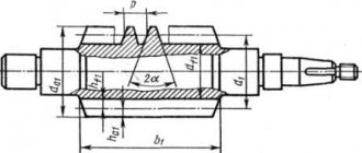
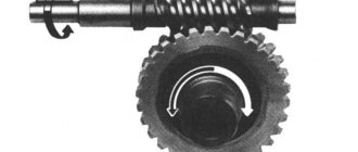
Worm-gear
The need to change the rotational motion at an angle requires the creation of a special type of system. Such structures include a worm gear. The main element of such a transmission can be cylindrical, globoid, involute, or Archimedean screw. This depends on the surface on which the thread is located and the profile of the thread.
The parameters used to calculate the gear ratio to be substituted into the expression are the existing number of worm gear runs. Typically it varies from one to four. The table of gear ratios for a worm circuit allows you to calculate the required number of gearing elements. The data given in this table helps to select the correct connections for a specific mechanism.
The main disadvantages of the transfer are:
- high heating temperature of the elements during rotation transmission;
- the presence of a slipping effect;
- braking and jamming;
- low efficiency;
- as a result, low reliability.
conclusions
The “classical” gear selection algorithm involves determining (strictly) the gear ratio in the highest gear and (not strictly) in the lowest gear. Afterwards, intermediate gears are distributed between these values.
You can start selecting intermediate gears with a uniform distribution with the same q index for all gears. After analyzing the dynamic characteristics constructed for this distribution, you can proceed to correction - small changes in the gearboxes towards bringing them closer together in higher gears.
Overdrive (a gear higher than the one at which maximum speed is achieved, usually fifth) in the classic algorithm is assigned after determining the gear ratio in fourth gear. To do this, you can set a typical indicator q for gears 4-5, analyze the dynamic characteristics and, if necessary, make changes.
Belting
This design is common. Its type is determined by the location of the shaft and the direction of movement of the belt. They are classified as follows:
- open type;
- cross shape;
- step system;
- angular.
To increase reliability, a paired connection is used. The implementation of such structures is carried out using belts of various sections. The most popular are three types: rectangular, trapezoidal, round.
The value of the gear ratio is calculated by substituting the rotation speeds of the drive and driven shafts into the classical formula. Sometimes the calculation uses the number of revolutions of each shaft. As an alternative, when calculating this parameter, the diameters (radii) of the pulleys are used.
About what happens
The simplest example of transmission is from the rotating wheel of a water mill to a millstone. In this case, there is often a change in the initial energy received by the wheel from the flowing water, in magnitude and direction. The magnitude of this change will be determined by the gear ratio. It describes one of the most important characteristics of energy conversion during rotational motion, defined as the ratio of the frequency or rotation speed of the element receiving energy to the same parameters of the element giving off energy.
In other words,
the gear ratio describes how the original energy received from an engine or any other energy source (water wheel, wind wheel, turbine, etc.) changes as it is transmitted. Throughout the history of technological development, humanity has created a wide variety of transmissions, for each of which there is a gear ratio that is a quotient of the speed of the driving link divided by the speed of the driven link.