Screw-cutting lathe TV-6
To carry out high-quality turning work, certain skills are required. The TV-6 lathe is used to teach the basics of the lathe profession, which determines its wide distribution in various training organizations. Despite the fact that the equipment became commercially available in the 80s, today a school lathe is quite common. Let's take a closer look at the features of this equipment.
Machine Specifications
The fact that the TV-6 lathe was developed for training determines very modest parameters. When using the equipment in question, the following operations can be performed:
- Drilling holes.
- Trimming the ends.
- Metric thread cutting.
- Boring and grooving of parts that have a cylindrical or conical surface.
- Cutting off part of the workpiece.
The widespread TV-6 lathe, the technical characteristics of which do not allow working with hardened steel, can be used for processing metals, the cutting of which does not produce volatile compounds or dust. TV-6 is characterized by the following characteristics:
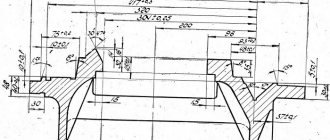
- The maximum diameter of the workpiece is 12 mm.
- The length of the surface to be turned is 300 mm.
- The height of the centers is 108 mm.
- The spindle speed varies in the range from 130 to 170 rpm.
- The distance between centers is 350 mm.
When considering the weight of a lathe, a student should take into account that the minimum configuration weighs 300 kilograms.
That is why during installation and transportation it is necessary to take into account the rather large weight; the model is installed on a foundation slab. This ensures vibration absorption during operation.
Features of use
Even though the TV-6 device is considered a training device, when working on it you can obtain high accuracy and work with complex turning operations. The drive mechanism of the unit uses a V-belt drive, so regular checking of the belt tension is required.
With such a simple preventive measure, maximum power of the electric motor is used and the service life of the work is extended. When the tension is loosened, it is easy to adjust the belts by loosening the nuts and setting the required tension level.
Another common malfunction of the device is vibration when the spindle assembly rotates, due to the loosening of the screw connection. In such a situation, more qualified repairs are required, in case of possible bearing failure.
If gaps are detected in the spindle, grinding of the ends is necessary. But only in the case of minor gaps of a radial and axial nature.
Purpose of the equipment
When considering the purpose of a lathe, attention should be paid to the fact that it is for training purposes. Despite this, metal turning can be carried out with a high degree of accuracy. Certain technical characteristics allow installation of equipment in home or educational workshops. When reviewing the instructions (manual), we note the following points:
- The manufacturer recommends tensioning the belt from time to time. Such prevention allows you to achieve maximum power and performance over a long period.
- For adjustment, it is enough to loosen the nut, after which the position of the electric motor changes. The device is located on a slide, so the pulleys do not move relative to each other.
- A fairly common problem is that serious spindle vibration occurs during operation. This happens due to the loosening of the screws.
In general, we can say that the model is not characterized by high performance.
This is why the model is mostly installed in educational institutions to obtain the required skills. If necessary, production activities can be carried out.
Download the passport (operating instructions) of the TV-6 lathe
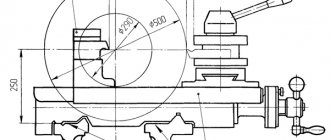
Caliper
The installation of cutters in the TV-6 metal lathe is carried out thanks to a support. Thanks to the presence of 4 slides (carriages), the cutters move:
- Along guides in the axial direction.
- In a direction perpendicular to the movement of the first carriage.
- In the axial direction along the guides of the third slide.
The carriages are installed in series, that is, on top of each other. The part is fixed to the fourth carriage using a special mechanism. When the handle is turned, the mechanism is pressed out and its position is secured with a pin.
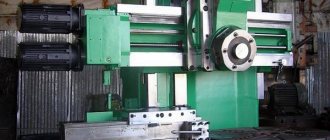
Structural elements of TV-6
The TV-6 screw-cutting lathe has a classic layout typical of turning group equipment. The main elements can be called:
- Front and rear stock.
- Transmission.
- Protective screen.
- An element designed to supply a lubricant.
- Bearing frame.
- Apron.
- Elements of a replacement guitar.
- Protective cover.
All nodes are located with high accuracy relative to each other. Some of them can be dismantled for replacement or maintenance.
Headstock and tailstock
The main elements of a lathe are the headstock and tailstock. Let's name their features as follows:
- The headstock serves to locate the spindle and gearbox.
- The tailstock is used to hold centers that can be used to support the end face of a large piece. By using centers, machining accuracy can be significantly increased
The TV-6 headstock provides access to the gearbox and replacement wheels, which allow you to change the parameters of the thread being cut
Feedbox and guitar replacement gears
Also important elements of the device are the feed box and a set of interchangeable gears. Let's call the key points:
- The replacement wheel guitar allows you to change the parameters of the thread cut on a cylindrical surface.
- The feed box does not require maintenance; lubricant is supplied to the contact area of the gears.
The model under consideration is characterized by high reliability. It can last for many years with proper maintenance.
bed
A frame is used to combine all the nodes. It is made using cast iron and is characterized by high rigidity. The bed has the following features:
- Reduces vibration.
- Provides accurate positioning of all nodes.
- At the time of installation, the device is securely positioned.
Precise positioning of all components ensures the required processing quality. The frame is painted with a protective compound in order to extend its service life.
Caliper
An important element is the caliper. It is used to secure the tool during processing. The installed caliper has classic characteristics:
- Provides reliable fixation of the tool.
- Can be positioned at a certain angle relative to the workpiece.
- Moves along the slide in the longitudinal and transverse directions.
The support can be used to fix various versions of cutters. Due to this, the scope of application of the lathe is significantly expanded.
Apron
The part of the structure on which the slides for moving the caliper are located acts as an apron. Steel is also used in its manufacture.
The features of the model under consideration include small overall dimensions. In addition, the device is characterized by relatively low energy consumption. To control the basic parameters of the device and processing modes, there are various switches, levers and keys. Rapid traverse can be used to quickly position an end-effector in a desired position.
How to buy a used machine
The easiest way to buy a used device is to go to the website for free advertisements for sale in the Russian Federation: Avito.ru. Unfortunately, despite the abundance of advertisements, there may not be enough choice for a particular region. There are other online selling resources. For example, the regional website “From Hand to Hand”. There are also weekly newspapers with the same or similar name. You can submit a purchase ad yourself.
- Warning: when buying from an ad in another region, you may end up with unscrupulous sellers. Or the product may not meet the declared condition, or they will offer a higher price. As a result, money for the trip will be thrown away. So it's better to look for an offer closer.
What to pay attention to when purchasing:
- Availability of chuck, jaws, tailstock, electric motor. Moreover, if the electric motor can still be purchased, then the tailstock is quite difficult to get (they are often sold for scrap metal, since they can be removed from the machine quite easily).
- It is necessary to make sure that the machine spindle rotates and the slide movement is activated. If the electric motor does not work, you can rotate the spindle manually using the drive pulley. If something doesn't rotate or move, there is obviously something wrong.
- Check how worn the rubbing surfaces are, as well as the radial chatter of the spindle and tailstock quill. Any fault found is a reason to reduce the price. If there are many faults, it is better to refuse the purchase even for a small amount. Because repairs can cost a pretty penny.
That's all that can be said in one article. Additional information can be found on thematic forums. It turns out that there are many people who enjoy learning the craft of turning and share their practical experience. Unfortunately, statements are sometimes controversial. In doubtful cases, it is better to seek advice from an experienced professional turner.
Technical characteristics of the TV-6 educational lathe
Since the TV-6 screw-cutting lathe was created in order to train beginners, it has rather modest technical characteristics. Using the equipment of this model, you can perform simple turning operations:
- trimming ends;
- drilling holes;
- boring and turning of parts of cylindrical and conical shapes;
- metric thread cutting;
- cutting off part of the workpiece.
TV-6 screw-cutting lathes are allowed to be used only for the manufacture of products made of steel and non-ferrous metals that do not emit volatile compounds and fine dust during processing that can have a harmful effect on the student’s body.
Structural elements of equipment
The TV-6 model lathe consists of the following components:
- feed control box;
- front and rear cabinets;
- protective screen;
- trough for supplying lubricating oil;
- headstock;
- device apron;
- tailstock;
- supporting frame;
- electrical system elements;
- guitar;
- protective casing.
Main components and controls of the TV-6 machine
The feedbox of the TV-6 lathe, driven by a gearbox using transmission gears, consists of:
- two shafts;
- five gears with different parameters;
- block gears;
- running roller;
- couplings;
- round nut;
- shift handles;
- drain plug.
The handle on the front side of the feed box allows you to determine the parameters of the thread cut on the workpiece.
Another handle, located on the feed box panel, is responsible for turning on the machine’s running roller. The design of this unit of the TV-6 machine makes it impossible to simultaneously turn on the lead screw and the lead roller. Models of lathes belonging to the category of industrial equipment are also equipped with a similar safety system. Lubrication of all feed box components (gears and rubbing surfaces) is ensured by oil supplied from the trough using special wicks.
Headstock device
Tailstock device
The front cabinet has a U-shaped configuration, and to enhance its rigidity, there are special ribs in its upper and lower parts. On its back side there is a drive electric motor of the unit, and on the front side there is a button that controls its reversing switches. The rear TV-6 cabinet has a similar design; a panel with electrical equipment is mounted on it.
The tailstock, which has a mounting hole for Morse taper No. 2, includes the following elements:
- base;
- unit body;
- connecting screws;
- quill;
- key screw;
- flywheel to control the movement of the quill;
- handles for fixing the quill and the tailstock itself.
The tailstock design allows the quill to be moved up to 65 mm.
The frame of the device, due to which all its structural units are connected and supported in a given position, has a box-like structure with several windows. There are two prismatic guides on the frame, along one of which (front) the carriage moves, and along the second (rear) the tailstock of the unit moves. The load-bearing elements of the frame itself, in the front part of which a rail with a lead screw is attached, are two pedestals.
The most important mechanism of the TV-6 lathe is its apron, in which it is necessary to highlight the following elements:
- four gears (two worm and two rack and pinion);
- control handles;
- handwheel for manual feed control;
- queen nut;
- a running roller responsible for the longitudinal feed of the caliper;
- shaft.
The support of the TV-6 screw-cutting lathe is composed of four carriages. This piece of equipment is responsible for fixing the cutting tool and moving it during metal processing. The tool holder, in which the working tool is fixed, is located on carriage No. 4; it is capable of moving along the guides of carriage No. 3 only in the longitudinal direction. The rotating carriage is No. 3, which is mounted on the second carriage. Carriage No. 2 is mounted on carriage No. 1, it is capable of moving along its guides in the transverse direction. Carriage No. 1 moves along the frame guides - in the longitudinal direction.
In order to transmit rotation from the gearbox of the unit to the elements of the feedbox, a transmission mechanism, also called a guitar, is used. The main structural element of the guitar is the bracket on which the gears are mounted. There are no replacement gears for the TV-6 machine, so the gear ratio provided by the guitar is constant and amounts to ¼.
TV-6 machine gearbox
Purpose and scope
A new model of the machine replaced the TV-4, a more outdated unit. Even with a simplified design, the TV-6 machine has all the necessary components of conventional screw-cutting devices.
It is equipped with a 6-speed spindle, 4 feed speeds into the caliper, and involves cutting metric threads without the need to rearrange the gears in the guitar.
TV-6 is suitable for tracking types of work:
- Grooving and boring of cylindrical and conical surfaces.
- End trimming.
- Segment.
- Metric thread cutting.
- Drilling.
Structural elements
The unit has a classic layout characteristic of this type of equipment. The main elements include:
- Front and tailstock.
- Feed box.
- Supporting frame.
- Replacement guitar.
- With protective casing and screen.
- A device that regulates the supply of lubricants.
- Availability of an apron.
Each element is located in its usual place, certain parts can be replaced and replaced during maintenance.
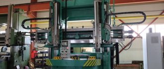
Cabinet
The design of the lathe divides the cabinet into two parts: front and back. They have a similar, but different structure.
The front cabinet is assembled in the shape of the letter “P”. To make the structure more durable, stiffening ribs are mounted at the bottom and top. The engine is located at the back of the cabinet. It turns on (off) by pressing a button located on the front of the cabinet.
The difference between the rear cabinet is that its design includes an electrical panel instead of a motor.
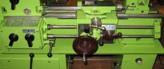
Control diagram
The control diagram has:
- A handle that sets the rotation speed of the spindle assembly.
- Another handle that sets the rotation speed of the spindle assembly.
- A handle that sets thread cutting (right and left) and changes the direction of feed.
- A handle that sets the feed rate and thread pitch.
- A handle that switches the roller.
- Reversing button that turns the machine on and off.
- Lever protecting the cartridge.
- Availability of a protective screen.
- Handle securing the cutting head.
- Light source for illuminating the workplace.
- A handle that manually moves the cross slide.
- A handle that moves the upper (incisor) slide.
- The handle that secures the quill.
- A handle that secures the tailstock towards the bed.
- Flywheels that move the quill.
- A button that turns the rack and pinion gear on and off.
- Flywheels that manually move the longitudinal carriage.
- A handle that adjusts the nuts in the lead screw.
- A handle that includes the maximum mechanical gear.
- Protective shield in front of the lead screw and shaft.
- Availability of transformer OSZR-0.063–83UHL3.
The machine assumes a basic configuration, discussed in detail below.
Cabinet
There is a front and rear cabinet.
The first has a U-shape and stiffening ribs in the lower and upper parts of the device.
The front cabinet has a reversing button on the body, which is responsible for turning the electric motors on and off.
There is a drive electric motor in the rear cabinet. It also has a U-shape, inside there is electrical equipment with a shield.
Feedbox and guitar replacement gears
An equally important element of the unit, the feed box and the guitar, their key features are discussed below:
- A set of interchangeable gears is used to change thread parameters.
- The feed box is driven by the gearbox using gears in the transmission mechanism, which includes:
- two shafts;
- five gears with different parameters;
- running roller;
- coupling;
- round nuts;
- shift handle;
- drain plug.
`
The handles on the feed box body determine the cutting parameters for workpieces. Another lever turns on the drive shaft of the unit.
Headstock and tailstock
The main element of any machine is the headstock and tailstock. Their main features and purposes are listed below:
- The purpose of the headstock is to locate the spindle assembly with the gearbox.
- I use the tailstock to secure centers; they are used to support the end surfaces of large products. Thanks to the use of the center, it is possible to significantly increase the accuracy of work.
Also, through the headstock, access to the gearbox and guitar is provided, which allows you to adjust the cutting parameter.
Apron device
The apron is part of the device that houses the slide, which is responsible for the smooth movement of the caliper. It is made of steel.
The apron structure consists of:
- handwheel;
- rack and pinion gear;
- shaft;
- worm gear;
- uterine nut;
- running roller.
Caliper design
The support secures cutting tools for ease of processing and moves it while working with metal. Four carriages form the basis of the caliper design.
In the fourth carriage, the tool holder fixes the working tools. It moves towards the third carriage, but only longitudinally.
Rotary carriage No. 3 is attached to the second carriage, the latter, in turn, is attached to the first, moving transversely.
The caliper has its own characteristics:
- It securely holds the cutting tool.
- It is located in a certain position in relation to the workpiece.
- Can move in longitudinal and transverse directions.
The support significantly expands the functionality of the machine.
Table of contents
photo: lathe TV 6
The TV 6 lathe is designed to teach schoolchildren and students the basics of turning and the production of simple parts in single-unit production conditions.
TV 6, like the TV 4 lathe and TV 16 lathe, allows you to perform the following turning operations:
- External and internal turning of cylindrical and conical surfaces
- Thread cutting, both with a cutter and a tap
- Drilling and hole reaming
- Trimming and cutting off parts, etc.
Controls of the TV 6 lathe
- Knob for setting the spindle head rotation speed;
- Knob for setting the spindle head rotation speed;
- Feed direction change handle;
- Handle for setting the feed and pitch of the thread being cut;
- Handle for turning on the roller and screw;
- Manual movement of the longitudinal carriage;
- Rack and pinion engagement;
- Turning on longitudinal mechanical feed;
- Engaging the lead screw nut;
- Manual movement of the cross slide;
- Manual movement of the upper slide;
- Mounting the cutting head;
- Fastening the tailstock quill;
- Moving the tailstock quill;
- Fixing the tailstock to the bed guides;
- Local lighting;
- Turn on the network;
- Control block
photo: lathe controls
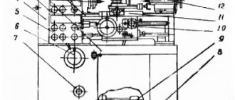
The device of the TV 6 lathe
- Headstock;
- Guitar Replaceable Gears;
- Gearbox;
- Apron;
- Caliper;
- Tailstock;
- Bed;
- Electrical equipment;
- Rear cabinet;
- Front cabinet;
- Protective cover
photo: lathe device
Kinematic diagram of the TV 6 lathe
photo: kinematic diagram of a lathe
Electrical circuit of the TV 6 lathe
photo: electrical diagram of a lathe
Headstock of lathe TV 6
The headstock is designed to support the workpiece being processed and transmit rotational motion to it. In the TV 6 lathe, the headstock is also a gearbox and has six speed levels.
The headstock is mounted along the center line in a horizontal plane using two setscrews. The headstock spindle is mounted on two thrust bearings 9 and a radial bearing 19.
The rotational motion is transmitted from the electric motor through a belt drive to the drive shaft of the gearbox. Inside the box, the movement is transmitted through shaft 2 and a fixed gear wheel 3 to a shaft 4 with fixed gears 12, 6 and a gear block 5.
Gear block 5 takes part only in feed reverse.
The rotation of the workpiece, fixed in a three-jaw chuck or faceplate, is transmitted from the spindle. When processing a workpiece at centers, a stationary center is inserted into the spindle.
The gearbox contains a device for changing the direction of the caliper. This is done by moving the gear 15 to the left or right position using handle 3.
In the left position of the gear 15, direct rotation is performed from the gear block 16. In the right position of the gear 15, reverse rotation is performed using the idler gear 6.
photo: lathe headstock
Guitar replacement gears of lathe TV 6
A guitar is a transmission mechanism that serves to transmit rotational motion from the gearbox spindle to the feedbox.
The guitar consists of bracket 1 and gears 2,4,7.
photo: lathe guitar
Feed box for school lathe TV 6
The rotational movement to the feed box is transmitted from the gearbox through a transmission mechanism.
By turning the handle 4 in three positions, the gear block 6 moves along the splines of the shaft 5 and alternately engages in gear engagement with gears 2,3,4. Which makes it possible to cut metric threads in increments of 0.8; 1; 1.25 mm and longitudinal feed of the caliper 0.08; 0.1; 0.12 mm/rev.
Handle 5 turns on the lead screw and the roller.
Lubrication of rubbing surfaces and gears is carried out with wicks.
photo: lathe feed box
Apron for table lathe TV 6
The apron is designed for mechanical longitudinal feed of the caliper from the running roller, screw and manual longitudinal feed.
Handwheel 1 performs manual feed. The flywheel sits on a shaft 4, on which a gear 11 is mounted, which meshes with gear 3. Gear 3 sits on the shaft of rack and pinion 2. The rack and pinion, in turn, meshes with the rack.
Mechanical feed is carried out by a worm 5 mounted on the running roller 10 using a keyed connection. The worm meshes with worm gear 13 and is then transmitted through the clutch to the rack and pinion gear.
photo: lathe apron
Apron
An apron is necessary for feeding the caliper from the running roller (screw) mechanically or manually. If you need to feed manually, you should rotate the flywheel, which is located on the pinion shaft. The latter connects with the gear, which is located on the shaft of the rack and pinion gear.
A worm connected by a sliding key to a roller provides mechanical feed. It transmits the movement to the worm gear. From there, the movement is transmitted to the rack and pinion gear through the next gear and cam clutch. The jaw clutch is connected to a handle, the rotation of which leads to mechanical feed.