TECHNICAL REQUIREMENTS
1. TECHNICAL REQUIREMENTS
1.1. Cartridges must be manufactured in accordance with the requirements of this standard, GOST 2675-80, GOST 3890-82, GOST 24351-80 according to working drawings approved in the prescribed manner.
1.2. Cartridge parts must be made of the following materials:
a) cartridge bodies made of cast iron in terms of quality indicators not lower than those of the SCh 30 grade according to GOST 1412-85 or made of steel with a tensile strength of at least 500 MPa and heat treatment of the working surfaces to a hardness of at least 43 HRC;
b) spiral disks of chucks of accuracy classes A and B, rods of wedge chucks and screws for moving the jaws of lathe chucks with independent movement of the jaws, accuracy classes A, B, P, N made of steel with a tensile strength of at least 500 MPa and heat treatment of working surfaces to hardness not less than 57 HRC, and the spiral disks of cartridges of accuracy classes P and N are made of steel with a tensile strength of not less than 500 MPa and heat treatment of surfaces to a hardness of not less than 43 HRC with a cemented surface layer thickness of not less than 0.5 mm;
c) the base of the cams, cams, racks, levers, bevel gears, seats and bushings of support bearings, made of steel with a tensile strength of at least 500 MPa and heat treatment of the clamping and rubbing working surfaces to a hardness of at least 43 HRC for accuracy classes N and P and not less than 50 HRC for accuracy classes A and B;
d) it is allowed to manufacture overhead jaws (blanks) from steel without heat treatment or from non-ferrous metals
1.3. Screws for fastening the cams must be used not lower than strength class 10.9 in accordance with the requirements of GOST 1759-70.
1.4, The parameters of the surface roughness of cartridges according to GOST 2789-73 should be no more than, microns:
| front and cylindrical surface of the chuck | Ra 0.80 |
| working surfaces of the grooves of the chuck body and cams, teeth of the cams and spiral disks, seating surfaces of spiral disks, grooves of the rod of wedge chucks and seating surfaces of housing hubs, chucks of accuracy classes N and P | Ra 1.60 |
| cartridges of accuracy classes A and B | Ra 0.80 |
| screw threads for chuck jaws with independent jaw movement | Ra 3.2 |
| jaw threads for chucks with independent jaw movement and gear tooth surfaces | Ra 6.3. |
1.5. The internal untreated surfaces of the cartridges must be cleaned and painted with oil-resistant paint.
1.6. For idle movement of the chuck cams, the torque applied to the key handle should not exceed the values given in Table 1.
Table 1
| Diameter of cartridges, mm | 80 | 100 | 125 | 160 | 200 | 250 | 315 | 400 | 500; 630 |
| Torque Nm | 3,2 | 4,0 | 5,0 | 6,0 | 8,0 | 10,0 | 12,5 | 16,0 | 20,0 |
1.7. The backlash of the key should not exceed 1/8 of its turn.
1.8. Self-centering chucks in assembled form must be statically balanced with the position of the cams corresponding to the outer diameter of the chuck, with an accuracy no less than that given in Table 2.
table 2
| Chuck diameter, mm | Limit values of permissible imbalance g cm for cartridges of accuracy classes | |||
| A | IN | P | N | |
| 200 | According to the standards agreed between the manufacturer and the consumer | |||
| 250 | 63 | 100 | 160 | 250 |
| 315 | 90 | 140 | 224 | 355 |
| 400 | 140 | 200 | 310 | 500 |
| 500 | 200 | 250 | 420 | 710 |
| 630 | 250 | 400 | 600 | 1000 |
1.9. Metric thread - according to GOST 24705-81*. Thread tolerance range 8g and 7N according to GOST 16093-81*. _______________ * GOST 24705-2004 is in force on the territory of the Russian Federation;
** GOST 16093-2004 is in force on the territory of the Russian Federation. — Note from the database manufacturer.
1.10. Thread exit, runs, undercuts, grooves and chamfers - according to GOST 10549-80.
1.11. The radial runout tolerance of the control band of self-centering cartridges with a diameter of up to 630 mm of accuracy classes A and B is no more than 10 microns, accuracy classes N and P are no more than 20 microns.
1.12. Tolerances of the shape and location of the surfaces of lathe chucks should not exceed the values given in Tables 3-6. Note. For chucks with prefabricated jaws, the test is carried out only when the ring is clamped by the internal steps. For chucks with independent movement of the jaws, only checks according to clauses 4.7.1 and 4.7.4 are carried out.
1.13. Tolerances of radial (clause 4.7.2 and 4.7.3) and axial (clause 4.7.4) runout for cartridges of accuracy class H with diameters of 125, 160, 200, 315 and 400 mm should not be more than specified in Tables 4-6 .
1.14. The minimum total clamping force of the chuck jaw must be 1/2 of the minimum total clamping force for two-jaw chucks and 1/3 for three-jaw chucks (see mandatory appendix 3).
1.15. The chucks are checked for the permissible rotation speed, which is determined from the condition of reducing the minimum total clamping force under the influence of centrifugal forces by 2/3 of the values specified in mandatory Appendix 3, with the cams positioned corresponding to the outer diameter. The permissible rotation speed is indicated in the operating documentation for the cartridge.
1.16. For cartridges of accuracy classes A, B and P, the established accuracy retention period must be at least 2 years, for cartridges of accuracy class N - at least 18 months.
Drive chuck
Double-jaw drive chucks are normalized (MH 4051 – 62); they can have a floating (spring-loaded) center.
A rapidly rotating drive chuck with a clamp can in some cases cause injury.
| Protective cover used when working with a driving chuck. |
A rapidly rotating drive chuck with a clamp is a source of increased danger and can cause injury.
The pneumatic lever driving chuck is used to secure and rotate workpieces mounted on centers.
The pneumatic lever driving chuck is used to secure and rotate workpieces mounted on centers.
A conventional universal drive chuck is shown in Fig. Under the influence of cutting forces, the workpiece rotates in a clockwise direction and the cams firmly jam the part. As the torque increases, the jamming, and therefore the clamping force, increases.
| Double jaw driver chuck with eccentric replaceable jaws, automatic action.| Chucks with two-jaw drive and sunken centers (dimensions in mm. |
Such leash cartridges, depending on their diameter, can accommodate loads with a total weight of 3 to 6 kg. Then, for example, with m – 3 kg, g 45 mm, n – 500, 1000, 2000 rpm, the centrifugal force pressing the cams to the workpiece will respectively be Rc 34, 138, 552 kgf.
Re-adjustable driving chuck designed by the Odessa Precision Machine Tools Plant. The changeover of the chuck is carried out by moving the strips 2 relative to the bushings 3 towards the center or away from the center of the chuck. The position of the strips is fixed with washers 7 and screws.
The adjustable pin driver chuck designed by NIIPTMASH (Kramatorsk) is intended for installation of workpieces such as shafts with diameters of 80 – 240 mm. The pointed pins can be reinstalled in the housing 8 along different circles depending on the diameter of the workpieces. Replaceable covers 10, fixed to the body 8, have corresponding oval holes that fit into the flats of the pins 9 to prevent them from turning. The pins 9 rest with their spherical ends on the spherical heel 6 mounted on the thrust bearing 5, which ensures self-alignment of the pins along the end of the workpiece. The extension of the floating center 11 and the adjustment of the spring force are carried out by rotating the glass 3 using the flats provided for this purpose. When installing the workpiece in the centers, the rotating center of the tailstock presses the workpiece in the axial direction and the pins cut into the end of the workpiece to the same depth, regardless of the non-perpendicularity of the end of the workpiece relative to its axis.
| Machining parts on rigid and floating front centers. |
The use of a drive chuck with a clamp is associated with a number of disadvantages.
The use of drive chucks eliminates the need to use clamps, which saves time on installing and securing the part and eliminates the possibility of vibration of the part during processing. In type A cartridges, cheeks 3 are mounted on plate 2, set to the size of the square end of the center mandrel. In type B chucks, driving cams 4 are installed to clamp raw parts.
The use of a driving chuck instead of a conventional clamp creates the opportunity to increase the rigidity of the installation of the shafts being turned. The workpiece, wedged between two eccentric cams, is, as it were, one whole with the moving part of the chuck. However, the presence of guaranteed gaps in the chuck mates (not selected when securing the workpiece) significantly reduces the rigidity of the entire system as a whole. Due to these gaps, the resemblance to a hinged support is maintained, since it remains possible to rotate the workpiece at a small angle.
COMPLETENESS
2.1. The cartridge kit includes:
a) key for cartridges with manual clamp - 1 pc.;
b) key for readjusting chuck jaws with power clamping - 1 pc. At the customer's request, chucks with solid jaws are equipped with direct and (or) reverse jaws, chucks with assembled jaws are equipped with only slats. The set of cartridges is accompanied by operational documentation, in which actual indicators must be indicated for cartridges of accuracy classes P, B and A.
II. Lathe chucks of the "ST" type, produced in accordance with GOST 2675-80.
All chucks of the “ST” type are steel self-centering 3-jaw. For chucks equivalent to DIN 6350 in terms of seating, the outer diameter in mm is indicated after the designation “ST”, then for chucks equivalent to DIN 55027 in seating, the cone number is additionally indicated after the letter F, and for those equivalent in DIN 55026 seating – the number 95.
At the end of the entry, the accuracy class of the cartridge is indicated: A - especially high, B - high and P - increased.
For example: type ST 250-F6 A means that it is a self-centering 3-jaw steel chuck with an outer diameter of 250 mm, having a mount for a rotary washer on a spindle with a cone No. 6 of accuracy class A.
ACCEPTANCE RULES
3.1. To verify compliance of the quality of cartridges with this standard, acceptance, periodic and type tests are carried out.
3.2. All cartridges must be subjected to acceptance tests in accordance with the requirements of paragraphs 1.4-1.6, 1.8, 4.7.1-4.7.4.
3.3. Periodic testing must be carried out at least once a year to ensure compliance with all requirements.
3.4. Type tests must be carried out when changing the design, materials of the main parts or manufacturing technology, if these changes may affect the parameters and quality of the cartridges.
3.5. During periodic testing, at least two cartridges that have passed acceptance tests are selected for each type of test.
3.6. Tolerance control of the shape and location of the surfaces of cartridges equipped with slats during acceptance tests is carried out in accordance with the technical specifications.
3.7. The established period of preservation of the accuracy of cartridges should be confirmed at intervals of at least once every three years based on the results of controlled operation of the products carried out in accordance with the established procedure. For controlled operation, 5 cartridges of each standard size and accuracy class should be installed. When carrying out controlled operation, accuracy control is carried out in accordance with paragraphs 4.7.2-4.7.4 of this standard at least once a quarter. The accuracy retention period is considered confirmed if all products delivered for controlled operation have retained the established accuracy.
TEST METHODS
4.1. Measuring instruments, control mandrels and rings must be regularly checked in accordance with current standards, rules and instructions of the USSR State Standard and additionally before and after acceptance and periodic tests, as well as in all cases where there is reason to assume that the device is faulty.
4.2. The absolute error of the measuring device during control should not exceed 10% of the maximum deviations for the product.
4.3. Tolerances of the shape and relative position of the surfaces of control mandrels and rings should be no more than 3 microns when checking with a tolerance of up to 30 microns inclusive and not exceed 10% of the verification tolerance in other cases.
4.4. When checking the accuracy of lathe chucks, only non-hardened jaws are bored. Manually driven chucks should be checked for accuracy when clamping the jaws from the zero gear. Check self-centering chucks with limited jaw stroke for accuracy:
a) with non-hardened cams (clauses 4.7.1-4.7.3) within the limits of the cam stroke only before strength tests. In this case, the diameters of control mandrels and rings are not regulated. The number of standard sizes of control mandrels or rings for checking the cartridge should be no more than 3.
b) with hardened jaws throughout the entire clamping range of parts.
4.5. When checking accuracy, the chucks are attached through an adapter flange to the spindle or directly to the machine spindle.
4.6. The maximum deviations of the machine spindle and adapter flange must comply with the standards given in reference Appendix 1.
4.7. Compliance of lathe chucks with the requirements of clauses 1.11-1.13 is controlled according to clauses 4.7.1-4.7.5.
4.7.1. Radial runout of the outer diameter of the cartridge or control belt in self-centering cartridges
Damn.1
Table 3
| Outer diameter of the cartridge, mm | Tolerances for radial runout of the outer diameter, µm, for cartridges of accuracy classes | |||
| A | IN | P | N | |
| 80 | 10 | 15 | 25 | 40 |
| 100 | ||||
| 125 | ||||
| 160 | 12 | 20 | 30 | 50 |
| 200 | ||||
| 250 | 15 | 25 | 40 | 60 |
| 315 | ||||
| 400 | 20 | 30 | 50 | 80 |
| 500 | ||||
| 630 | 40 | 60 | 100 | |
Chuck 1 is mounted through an adapter flange or directly onto the machine spindle. Measuring device (indicator) 2 is installed perpendicular to the axis of rotation of the spindle so that the measuring tip touches the outer surface of the cartridge or control belt. Rotate the cartridge 360° twice. The test results must comply with the standards given in Table 3 and clause 1.11.
4.7.2. Radial runout of the control mandrel clamped in the straight jaws of the self-centering chuck
Damn.2
Table 4
| Outer diameter of the cartridge, mm | Diameter of the control mandrel, mm | Overhang of control, mandrel, mm | Tolerances of radial runout, microns, for cartridges of accuracy class | |||
| A | IN | P | N | |||
| 80 | 8; 12; 15 | 40 | 20 | 30 | 50 | 60 |
| 100 | 12; 16; 18 | |||||
| 125 | 16; 20; 28 | 50 | 75 | |||
| 160 | 20; 32; 40 | 25 | 40 | 60 | ||
| 200 | 25; 32; 45 | 80 | ||||
| 250 | 32; 50; 55 | 80 | 30 | 50 | 80 | 100 |
| 315 | 50; 80; 100 | 120 | ||||
| 400 | 40 | 60 | ||||
| 500 | 55; 80; 125 | 160 | 50 | 80 | 100 | 120 |
| 630 | ||||||
The control mandrel 3 is clamped with the jaws of the chuck 1. The mandrel is clamped after preliminary gripping and turning it in the jaws. Measuring device (indicator) 2 is installed perpendicular to the axis of the control mandrel so that the measuring tip touches its surface. Rotate the cartridge 360° twice. The measurement is carried out sequentially with mandrels of all diameters given in Table 4, and at a distance from the end of the cams indicated in the table.
4.7.3. Radial runout of the control ring clamped by the outer steps of the forward jaws and the inner steps of the reverse jaws of the self-centering chuck
Damn.3
Table 5
| Outer diameter of the cartridge, mm | Radial runout tolerances, microns, for cartridges of accuracy classes | |||
| A | IN | P | N | |
| 80; 100 | 20 | 30 | 50 | 60 |
| 125 | 75 | |||
| 160; 200 | 25 | 40 | 60 | |
| 250; 315 | 30 | 50 | 80 | 100 |
| 400 | 40 | 60 | ||
| 500; 630 | 50 | 80 | 100 | 120 |
Control is carried out using the control ring 3, which is clamped sequentially by the working stages of the cams (direct and reverse) of the cartridge 1. The measuring device (indicator) 2 is installed perpendicular to the axis of the ring at a distance of 10 mm from the end of the cams so that the measuring tip touches the outer or inner cylindrical surface control ring. Rotate the cartridge 360° twice. The dimensions of the control rings are given in reference appendix 2. Control of runout of the control rings must be carried out with a minimum clamping force of 20% of the values of the minimum total clamping force specified in mandatory annex 3. The test results must comply with the standards given in table 5.
4.7.4. Axial runout of the control ring clamped by the inner stages of the reverse cams and the outer stages of the forward cams
Damn.4
Table 6
| Outer diameter of the cartridge, mm | Tolerances of axial runout, microns, for cartridges of accuracy classes | |||
| A | IN | P | N | |
| 80; 100 | 15 | 20 | 30 | 40 |
| 125; 160; 200 | 20 | 30 | 40 | 50 |
| 250 | 50 | 70 | ||
| 315; 400 | 30 | 40 | ||
| 500; 630 | 80 | |||
4.7.5. Ammo Durability
Strength testing of cartridges is carried out by turning a pre-processed workpiece made of grade 45 steel, clamped in jaws (without using a rear center), according to GOST 1050-88. To turn the workpiece, a through cutter with a main lead angle of 45° should be used. The design and material of the cutter are not regulated. The dimensions of the workpieces and cutting conditions during testing for accuracy classes N and P must correspond to the data given in Table 7.
Table 7
Dimensions in mm
| Name of workpiece parameters | Processing modes for workpieces in chucks with diameter | |||||||||
| 80 | 100 | 125 | 160 | 200 | 250 | 315 | 400 | 500 | 630 | |
| Diameter of the workpiece to be turned | 22 | 25 | 35 | 55 | 75 | 95 | 120 | 150 | 190 | 230 |
| Length of the protruding part of the workpiece from the end of the jaws | 30 | 40 | 50 | 70 | 90 | 110 | 130 | 150 | 180 | 210 |
| Depth of cut | 1,4 | 1,6 | 1,8 | 2,4 | 2,6 | 3,0 | 3,5 | 4,0 | 4,5 | 5,0 |
| Feed, mm/rev | 0,3 | 0,4 | 0,5 | 0,6 | 0,7 | 0,8 | 0,9 | 1,0 | 1,1 | 1,2 |
Note. It is allowed to set the closest feed and speed available on the machine, provided that the specified chip cross-section is maintained. For cartridges of accuracy classes B and A, cutting modes are regulated by technical conditions. After checking for strength, the accuracy of the cartridges must comply with the requirements of paragraphs 1.11, 1.12. The cutting speed when testing chucks is 20 m/min. For safe operation, the center of the tailstock must be connected to the center hole of the workpiece with a gap of no more than 1.5-2 mm. The torque on the chuck key with a manual drive and the clamping force of the workpiece with a mechanized drive are not regulated. It should be considered that the chuck passed the cutting test if the workpiece did not touch the center of the tailstock during operation and was rotated in the cams at an angle of no more than 15°.
4.7.6. Minimum total clamping force
The clamping force is checked on one jaw with a ring dynamometer or another device, which is previously calibrated on a prism with an angle of 120°, if the test is carried out for three-jaw chucks. Clamping is carried out at the maximum torque on the wrench for manually driven chucks or the maximum force transmitted by the drive for power-operated chucks, specified in mandatory Appendix 3.
General design and arrangement of a lathe chuck for a metal machine
The following kits are supplied with the cartridge:
- straight cams;
- reverse cams;
- Cam racks are supplied outside the kit.
The most common is the three-jaw chuck, consisting of:
- monolithic or composite body with three radial grooves for cams;
- cams (direct and reverse) are made of high-quality hard, hardened steel of high strength, connected to the end thread of the spiral disk;
- spiral disk, with a large gear on its reverse side. Associated with the bevel gear gear;
- bevel gears, by rotating a key inserted into the square hole of this gear, a rotational movement is imparted to the spiral disk.
The simplicity of technological methods for basing parts has become the reason for the popularity and spread of the three-jaw chuck on machines used in production
Key
A metal rod, at one end of which a hole is drilled perpendicular to its axis with a metal lever installed in it. Exceeding the length of the lever by 35–40% relative to the height of the key is optimal.
At the lower end of the rod there is a tetrahedral tip, commensurate with the hole inside the bevel gear. Serves as a manual drive of the cams by rotating the spiral disk while securing the workpiece in the working area of the machine.
Spring
Installed on the tip of the key. Upon completion of the operation, the load from the efforts of the hand on the key is removed and the spring, straightening, removes the key from the cartridge socket. If the machine operator inadvertently does not remove the key himself, then the spring does it for him.
Sleeve
A hollow cylinder, in the upper part of which grooves are cut for half-ring crackers. Provides fixation of the bevel gear in the working body of the cartridge. The upper part of the bevel gear with a groove for half-ring crackers is installed in the inner diameter of the bushing.
Gear
The bevel (or small) gear is inserted into the small hole in the chuck body. Its upper part is connected to the grooves of the bushing by means of half-ring crackers.
The small gear is constantly meshed with the teeth of the large gear and is designed to transmit rotational motion to the helical disk of the chuck.
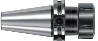
Flange
Adapter flange, faceplate. Designed for a strong and precise connection of the chuck with the working end of the machine spindle. For example, a thread is cut on the TV-4 spindle, an adapter flange (faceplate) is installed on it, onto which the lathe chuck is attached.
Spiral disk
Archimedes spiral, snail, planetary. A metal disk with large gear teeth on one side that are permanently meshed with the bevel gear gear.
On the other side of this disk, a spiral profile is cut out, which is in constant contact with the grooves (racks or combs) of the cams. The latter, moving synchronously, work to clamp, center and fix the part in the processing area of the machine.
The part clamped by the cams is removed by rotating the chuck key in reverse.
Reverse cam
Used for clamping large diameter parts. Each cam has two stages for fastening parts for expansion and one prism for compression.
Cam stages are used to eliminate end runout of the part. In addition, machine operators independently create an additional fastening base on the return cams that works to expand.
Frame
Depending on the design and methods of attachment to the spindle, it can be conditionally divided into monolithic (the body is one basic part) and composite, in which the body is divided into two basic parts:
- Monolithic with a cylindrical belt. It is attached to the spindle through an intermediate flange according to special GOST. Made from high-quality steel and less often from cast iron.
- Composite body. The base part is divided into two components:
- the front part or body (sometimes the front semi-body), it contains a spiral disk and slots for the cams;
- the rear part or flange (often the rear half-body), which houses bevel gears.
Top jaws
They are mounted on the cam rails of the lathe chuck. They are made from unhardened steel grades and are called “raw cams”. Designed for fastening large diameter parts.
LABELING, PACKAGING, TRANSPORTATION AND STORAGE
5.1. Mark on the cartridge:
a) designation and accuracy class of the chuck, except for accuracy class N. On chucks with manual drive, mark the location of the zero gear with the number 0;
b) trademark of the manufacturer;
c) serial number and year of manufacture of the cartridge;
d) number of grooves; The cams or cam bases must be marked with numbers corresponding to the slot numbers.
e) permissible rotation speed for mechanized drives;
f) maximum dimensions of the fastened part;
g) total clamping force.
5.2. Conservation - according to GOST 9.014-78 (II group of products). The technical specifications must indicate the preservation date and shelf life without re-preservation.
5.3. Cartridges to be transported are packed in plank boxes of types III-VII in accordance with GOST 9396-88, of sheet wood materials of types V, VI in accordance with GOST 5959-80, plank boxes of types III, IV, VI in accordance with GOST 2991-85, type II in accordance with GOST 10198-78*, types IV in accordance with GOST 26014-83, lined with waterproof paper in accordance with GOST 8828-89 or bitumen paper grade BU-B in accordance with GOST 515-77, or universal containers of types AUK-1.25 and UUK-3 in accordance with GOST 18477 -79. _______________ * GOST 10198-91 is in force on the territory of the Russian Federation. — Note from the database manufacturer. When transporting several pieces of cargo to one address, it is necessary to form them into transport packages in accordance with GOST 24597-81.
5.4. Transportation of cartridges is carried out by all types of transport in closed vehicles in accordance with the rules of cargo transportation in force for a specific type of transport.
5.5. Requirements for transport markings are in accordance with GOST 14192-77*. _______________ * GOST 14192-96 is in force on the territory of the Russian Federation. — Note from the database manufacturer.
5.6. Finished products must be stored packaged in a dry, closed area. Storage conditions: 2 or 3 according to GOST 15150-69.