Worm gears are used in a wide variety of industrial applications. Worm wheels and worms are used to increase torque, but by changing the angle of inclination you can also reduce the speed. A particularly important point in the manufacture of worm gears is accuracy, since if the parts are made inaccurately, there is a high probability of the unit jamming. There are special requirements and standards for the manufacture of parts for worm gears; these are requirements for the accuracy of the lateral clearance and the type of mating.
It follows that gear-screw transmissions are produced using the latest, high-precision machine tools. Our company MetalService is ready to fulfill all customer requirements; we have enormous experience in the field of metalworking and the production of various metal parts. To comply with all manufacturing tolerances, we employ highly qualified and professionally trained employees, who, combined with experience and machines, produce high-quality parts. All our company’s products comply with strict technological standards and guarantee long-term, reliable operation of your equipment.
Worm pairs: worm wheels and worms
The worm pair transmits rotation along intersecting (but not intersecting, unlike bevel gears) axes.
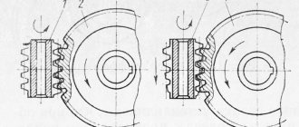
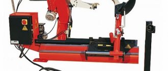
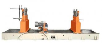
The worm pair consists of a worm wheel and a worm. The worm wheel is made of antifriction material (cast iron, bronze). Often the middle part of the worm wheel is made of steel, and a crown made of bronze (sometimes cast iron) is put on it. The worm is a screw with a special “thread”. Worms are made not only single-start, but also multi-start (as, for example, in the pictures above).
The production of worm wheels and the production of worms is a very popular operation due to the widespread use of worm gearboxes, which is due to a number of advantages of worm pairs:
- large gear ratios in one pair and, as a consequence, compactness of gearboxes;
- often, ease of arrangement due to the crossing of the shaft axes;
- smooth and quiet operation;
- at a small lifting angle of the worm, they have a self-braking effect, being irreversible (you cannot rotate the worm by applying force to the worm wheel).
Disadvantages of worm pairs:
- increased friction losses and, as a result: high requirements for assembly quality; low efficiency;
- heat generation;
- high wear;
Cutting worms and worm wheels
Worm gears are widely used in mechanical engineering due to their compactness, silent and smooth operation.
The cross-section of the turns of a cylindrical worm with an axial plane is a rectilinear rack, while for a globoid worm it is a circular rack.
Among cylindrical worms, the screw worm (with an Archimedean spiral), which is an ordinary screw with a trapezoidal thread, has received the greatest use for non-critical gears (Fig. 106, a). Despite the ease of processing, a worm pair with such a worm has low efficiency and is subject to rapid wear, so it is used in non-critical, low-speed and lightly loaded gears. Another type of cylindrical worm is an involute worm (Fig. 106, b). It is like a cylindrical gear with helical involute teeth.
In the section of the worm by planes perpendicular to the axis of the main cylinder, involutes are obtained. Such worm pairs are often used in critical transmissions at high loads and speeds.
A simple type of cylindrical worm is a worm with a rectilinear profile in the normal section of the coil and with an involute side of the coil in the section transverse to the axis (Fig. 106, c). Such a worm is called convoluted and is a type of involute worm. These worms are easier to process than involute worms, and provide sufficient accuracy of engagement of the worm gear, have high efficiency and wear resistance.
Globoid worms have a large contact surface between the turns and the teeth of the worm wheel, which reduces pressure and, consequently, wears the surfaces of the teeth of the worm pair. Due to the complexity of manufacturing, they are widely used only in high-power transmissions.
The simplest and cheapest way to make turns of a worm with an Archimedean spiral is cutting with a cutter on a screw-cutting lathe. The cutter is installed so that its straight cutting edge lies in the axial plane of the worm. In this case, the helical surface is formed by rotation of the workpiece and the movement of the cutting edge passing through the axis of the worm. The helical surface of such a worm is called Archimedean, since in the section of the worm perpendicular to its axis, an Archimedean spiral is obtained (Fig. 106, a).
In Fig. 106, b shows a method for cutting turns of an involute worm. In this case, the cutter is installed so that one of its straight cutting edges is located above, and the second below the axial plane of the worm by the radius r0 of the main cylinder of the helical involute surface.
The formation of a helical surface occurs when the workpiece rotates and the cutting edge of the cutter moves tangentially to the forming cylinder of diameter 2r0. Such a helical surface is called involute, since an involute is obtained in the end plane of the worm.
When cutting turns of a convolute worm (Fig. 106, c), the cutters are installed so that their cutting edges are in a plane normal to the helical surface.
The formation of the helical surface of a convolute worm occurs in the same way as the surface of an involute worm - during the movement of the straight cutting edge of the cutters, when it remains tangent to the forming cylinder.
The described method of cutting worms with cutters is accurate, but ineffective. In mass production, worm turns are performed by milling with disk or worm cutters, as well as by rolling with cutters.
Milling with disc cutters is carried out on special thread-cutting machines. The cutter has a cavity profile in a normal section and is installed at an inclination angle of the helix β (Fig. 107). The full depth of the screw is milled at once. For one revolution of the product, the cutter moves by one step. Due to the distortion of the profile of the turns, cutting with disk cutters is a preliminary processing of the worm profile.
Along with cutting worms with a disk cutter, various types of worms are processed with a hob cutter on conventional gear milling machines. The machine is set up to cut a cylindrical gear with helical teeth, the number of which is taken to be equal to the number of worm passes.
The most accurate and highly productive way of processing worms is cutting the worm with a cutter (Fig. 108). The cutter 1, installed relative to the axial plane of the cut worm 2, has a feed movement along the axis of the worm. In addition, the cutter and the worm are given a rotational rolling motion by adjusting the kinematic chain of the machine. As a result of the combination of these movements, all the turns of the worm are cut.
To cut worms with a helix angle of less than 5-6°, the cutter is made with straight teeth, and for a helix angle of more than 5-6° - with oblique teeth. However, the need to manufacture cutters for each elevation angle of the turns of the cut worms increases the cost of production preparation, so the use of this method is economical only in large-scale or mass production.
The most widely used when cutting globoid worms are multi-cutting heads, which perform a rotational movement in a plane passing through the axis of the worm (Fig. 109).
Profiling cutters 1 and 4, the cutting edges of which have the profile of the main section of the coil, process the coil along its lateral sides, the cutter 3 of the head grinds the worm along the outer globoid.
The operation of cutting a worm with cutting heads is divided into two transitions. In the first transition, processing is carried out with radial feed of the table to the nominal interaxial size. The first transition is intended for cutting a cavity to the depth of the profile. The second transition is performed at a constant center distance and is designed to obtain a given coil thickness with a surface roughness of at least 2.50 microns (6th class). The sides of the coil are processed alternately, with a circular feed of the cutters.
Before finishing, it is necessary to deepen the cutter into the worm being cut to remove the allowance for finishing cutting. This is done by rotating the machine table with the cutting head through the differential chain. Processing is carried out with a cutting speed v ≤ 1 m/min and a feed to the cutter s = 0.02-0.04 mm with abundant cooling with a mixture of vegetable and animal oils. For finishing, the recess on the side of the coil is 0.5-1 mm.
After cutting the turns, the worm is heat treated, cemented, hardened and tempered to a given hardness.
The grinding of the turns is carried out on a gear-cutting machine with a special grinding head, which rotates the axis of the grinding wheel to the corresponding angle of elevation of each point of the turn. Finishing of globoid worms is carried out by lapping or rolling with a hardened polished roller on a special machine. Surface roughness reaches 0.08 microns (10th class)..
The processing of worm wheels is carried out on gear hobbing machines using hob cutters using three methods:
- 1) radial feed method;
- 2) tangential feed method;
- 3) combined method.
With the radial feed method, workpiece 1 (Fig. 110, a), being constantly engaged with hob cutter 2, makes a radial feed to the cutter to the set size, while the cutter makes only rotational movement. The worm wheel produces a more correct tooth profile when the hob cutter is fully engaged with the workpiece.
The disadvantage of this method is that the hob cutter does not work with all cutting edges and only the teeth of the middle part of the cutter wear out.
With the tangential feed method (Fig. 110, b), the workpiece of the worm wheel 1 is set to the size of the center-to-center distance A and the cutter is inserted with the workpiece by axial movement. Milling cutter 3 has a conical intake part and, working with all cutting edges, wears out evenly. During the cutting process, the cutter not only rotates, but also moves forward along its axis. In this case, the workpiece, in addition to the main rotational movement associated with engagement, has an additional rotational movement depending on the axial movement of the cutter, otherwise the teeth of the hob cutter cut off the teeth of the worm wheel.
The combined method of cutting worm wheels is a sequential combination of the first two methods. Moreover, the radial feed method is used for preliminary cutting of teeth, and the tangential feed method is used for final processing.
With the combined method, both hob cutters and profile cutters are used. The use of profile cutters for final processing of the worm wheel provides the highest accuracy.
The processing of globoid gear teeth is similar to the processing of conventional worm wheels and is performed with a special tool. In Fig. 111 shows a cutting diagram for a globoid worm wheel and the design of the cutter. Cutting the teeth of a worm globoid wheel is carried out in two transitions - cutting to the depth of the profile with radial feed of the table to the nominal center-to-center size and finishing cutting at a constant center-to-center size with circular feed.
Before the finishing pass, the cutter is deepened into the wheel being cut to remove allowance for finishing cutting. This is done by turning the machine table with the wheel being processed through the differential chain. Milling ends when the specified tooth thickness and surface roughness are not lower than 20 microns (5th class).
Finishing of globoid worm wheels during mass production is carried out by shaving with a globoid worm wheel (Fig. 112); The allowance for shaving does not exceed 0.05–0.1 mm. In individual production, this method is not justified, since such a shaver is an expensive tool.
Production of worm pairs here
We have been manufacturing worms and worm wheels to order in St. Petersburg for almost a quarter of a century. And with us, of course, you can produce not only worm wheels and worms, but also the production of other types of gears:
- spur gears;
- cylindrical helical gears;
- cylindrical gears with an internal crown;
- spur bevel gears;
- gears with a circular tooth;
- gear racks,
as well as sprockets and spline connections, manufactured according to the Customer’s drawings or samples.
You can get acquainted with our capabilities for the production of gears, sprockets and spline cutting here.
Find out about our other opportunities in the field of custom metalworking services on the main page of our website.
Technological production process
The production of worms and worm wheels is carried out, as a rule, in two main ways:
- Cutting with a cutter on a screw-cutting lathe. This method is characterized by fairly high accuracy, but its disadvantages include low productivity.
- Cutting with a milling cutter on a milling machine. This method is more productive.
Worm milling is one of the most complex gear hobbing operations, but the use of modern equipment with software makes it possible to achieve the highest precision in the manufacture of products of any profile.
After applying the thread, some types of worms are strengthened by heat treatment, ground and, if necessary, polished. These operations are necessary to improve the performance of the worm gear, which depends on the hardness and roughness of the worm surface.
The production of worm wheels can be carried out in several ways, but higher quality and more productive - with the use of worm cutters.
The process of manufacturing a worm part depends on many factors: the design of the part, the choice of technological process, machines and devices, the workpiece, its processing mode and tools. Taking into account all these nuances, you can obtain a high-quality part with the specified physical and chemical properties at the best price.
Manufacturing of cylindrical worm gears
The most common types of worms in cylindrical worm gears are the following (GOST 18498 - 73): Archimedean (ZA), involute (ZI),
convolute with straight helix profiles (ZN1), convolute with rectilinear cavity profiles (ZN2), convolute with a straight normal helix profile (ZN3) and formed by a cone (ZK1) and (ZK2).
In recent years, transmissions with worms have been used, the turns of which in the normal section have profiles in the shape of a circular arc - cylindrical worms formed by a torus (ZT1).
The geometry of each of these types of worms is associated with its own technological methods.
Depending on the scale of production and hardness, cutting turns of cylindrical worms can be done in various ways. In single and small-scale production, worms that are not subjected to heat treatment or heat-treated to a hardness of HRCe 38 are cut with profile cutters, disk or finger cutters, and in serial and mass production - by a vortex method or plastic deformation. For worms hardened to a hardness of HRCe 51 or more, the finishing operation for processing the working surfaces of the turns is grinding.
The main technological feature of the geometry of cylindrical worm gears, which distinguishes them from other types of gears, is that the producing surfaces (producing worm) of the tool when cutting the teeth of a worm wheel using the rolling method must coincide or in a certain way differ slightly from the working surfaces of the worm itself. As such a tool, hob cutters are usually used, which are a cylindrical worm, the turns of which are intersected by helical grooves to form cutting edges, and the side surfaces and surfaces of the apexes have backs to form rear cutting angles. The cutting edges of the cutter must lie on the imaginary surface of the worm of the required type.
The worms and worm wheels themselves, before the formation of the gearing elements, are bodies of rotation and conventional processing methods are used in their manufacture.
Processing of threads of cylindrical worms
Cutting cylindrical worms with profile cutters
On lathes
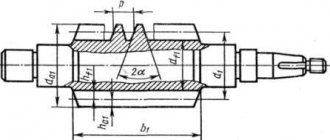
The Archimedes worm ZA has a rectilinear coil profile in the axial section AA (Fig. 3.4) and a curved profile in the normal section. The end section of the coil is an Archimedean spiral. The involute worm Z1 has a rectilinear coil profile in the section with a plane tangent to the main cylinder, and a curved profile in the normal section; the end section is an involute. The coil of the convolute worm ZN1 has a rectilinear profile in the explosive section ,
perpendicular to the turn, the turn of the worm ZN2 is in the section BB
,
perpendicular to the cavity, and the turn of the worm ZN3 is in the sections GG
,
perpendicular to the lines of the turn. All convolute worms have a curved coil profile in the axial section AA, and an elongated or shortened involute in the end section.
Rice. 3.4. Sections of cylindrical worms: AA - axial, BB - section normal to the cavity; BB - section normal to the turn; GG —
section normal to the coil lines
The most technologically advanced worms are ZA, the processing of which on a lathe is practically no different from the processing of screws with trapezoidal threads. The cutter is installed so that its cutting edges lie in the axial plane of the worm. The installation of a double-sided cutter with a straight profile is shown in Fig. 3.5. This method of cutting a helix can only be recommended for worms with a small helix angle due to the difference in cutting conditions on the left and right sides. For finishing cutting of ZA worms with a helix line elevation angle of up to 10°, it is recommended to separately process the left and right sides of the helix with single-sided cutters.
The installation of single-sided cutters is shown in Fig. 3.6. When cutting worm turns with a one-sided cutter, it is possible to alternately process both sides of the cavity with one cutter by turning the worm.
| Rice. 3.5. Installation diagram of a double-sided cutter when cutting a ZA worm | Rice. 3.6. Scheme for installing one-sided cutters when cutting a ZA worm |
The cutter installation diagram for cutting worms of type ZN1 and ZN2 is shown in Fig. 3.7, 3.8.
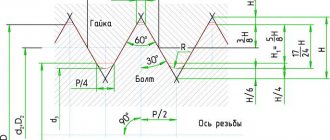
Convolute worms (ZN1 and ZN2) are cleanly cut with one or two cutters with straight cutting edges, located for the ZN1 worm (Fig. 3.7) in the normal section of the turn and for the ZN2 worm (Fig. 3.8) in the normal section of the cavity. The angles of the coil profile anT and in the normal section of the cavity anS according to GOST 19036 - 73 are assumed to be the same, equal to 20°.
The installation of the cutter for cutting a coil of a ZN3 worm with a straight profile in a section normal to the profile is the same as for cutting the coils of a ZN2 worm.
| Rice. 3.7. Diagram of installation of cutters for cutting a coil of a ZN1 worm (with a straight profile in a section normal to the coil) | Rice. 3.8. Installation diagram of a double-sided cutter for cutting a coil of a ZN2 worm (with a straight profile in a section normal to the cavity) |
When cutting an involute worm ZI, cutters having a straight profile are installed so that the horizontal plane passing through the cutting edge is tangent to the main cylinder. The installation of cutters when cutting involute worms is shown in Fig. 3.9, 3.10.
| Rice. 3.9. Installation diagram of cutters for cutting the right worm ZI | Rice. 3.10. Installation diagram of cutters for cutting the left wormZI |
Cutting cylindrical worms using milling method
Milling is carried out on thread milling, gear hobbing or special machines for milling worms. Disc or finger cutters are used as tools. Milling is a more productive operation than cutting with cutters.
Disc cutters for preliminary cutting of all types of worms are made with a trapezoidal profile. For finishing milling or for grinding turns, each standard size of worm must correspond to a special cutter with curved cutting edges.
Cutting worms with disc cutters is mainly used for rough milling of worm turns, worms no more precise than the 9th degree of accuracy.
In the case of using disk cutters with straight cutting edges and the location of the cutter axis at an angle g (Fig. 3.11) to the worm axis, only ZK1 type worms, in which the generatrices of the helical surfaces are not straight lines, can be completely milled.
| Rice. 3.11. Diagram of installation of a disk cutter when cutting cylindrical worms |
To facilitate the production of ZI and ZN worms, it is allowed to use cutters with a straight profile, provided that the resulting error in the worm profile is less than the tolerance left for finishing.
The milling method is used to pre-process worm turns with concave profiles of the type ZT1 (cylindrical worms formed by a torus, the axis of which is crossed with the axis of the producing torus at an angle equal to the pitch angle of the worm's turn), ZT2 (cylindrical worms formed by a torus, the axis of which is crossed with the axis of the producing torus at an angle at which one of the flat sections of the main surface of the worm is an arc of a circle coinciding with the generatrix of the generating torus).
The tool used is a disk cutter with a mountain-shaped surface.
Finger cutters are used for milling turns of large worms when it is not possible to use any other tool.
Gearing with rolling cutters (vortex cutting of turns)
This method consists of cutting worms by turning with continuous rolling. The tool used is a spur or helical involute cutting wheel (resembling a gear cutter). There is a forced kinematic connection between the rotation of the worm and the cutter. Feed during cutting occurs due to the axial movement of the worm workpiece (or a support with a cutter) with synchronous additional rotation of the cutter (Fig. 3.12). Cutting worms using the gear turning method can be done on special machines (model EZ-10A) or gear hobbing machines with a tangential feed feed. Depending on the geometry and sharpening of the cutter, as well as on the relative position of the worm and cutter, worms with different geometries can be processed (Archimedean, convolute, involute).
| Rice. 3.12. Cutting a worm using the tooth turning method |
For worms subjected to heat treatment, cutting is a preliminary operation performed with an allowance for grinding.
Rolling turns of the worm.
Rolling is the most productive and least material-intensive processing method. Rolling is carried out on roller rolling machines (mills). Worms with m < 3 mm are rolled on two-roller machines in a cold state, and with m ³ 3 mm - on three-roller machines, usually heating the workpiece using high-frequency heat. The schematic diagram of rolling machines is shown in Fig. 3.13.
| A ) | b ) |
| Rice. 3.13. Schematic diagrams of machines for rolling worms: a ) - three-roll; b ) - two-roll; 1 - blank; 2 - movable roller; 3 — supporting knife; 4 - stationary roller |
Deviations in dimensions (mm) of screw surfaces of worms obtained by cold rolling (m = 1...2 mm) are as follows:
By step………………………………………………………………………………….0.015
According to the thickness of the tooth at the pitch diameter………………………….0.02 - 0.03
According to the radial runout of the worm coil relative to the axis of the centers...0.1 - 0.25
According to fluctuations in the diameter of the depressions……………………………………………..0.05
If the center holes are processed after rolling, basing the workpiece on the working profiles, then the radial runout can be reduced to 0.04 - 0.08 mm. Thus, by cold rolling it is possible to obtain worms corresponding to the 8th degree of accuracy, and for certain parameters - to the 7th degree of accuracy.
The deviations in dimensions (mm) of the helical surfaces of worms obtained by hot rolling are as follows:
By step………………………………………………………………………………… 0.03 - 0.05
According to the thickness of the tooth at the pitch diameter…………………………. 0.03 - 0.05
According to the radial runout of the worm turn relative to the axis of the centers....0.3 - 0.8
According to fluctuations in the diameter of the vertices, no more than……………………………………0.4
According to fluctuations in the diameter of the depressions at m < 5 mm, no more than………………………0.1