Worm gears
General information.
In worm gears, the shaft axes intersect.
Typically the crossing angle is 90°. A worm gear consists of a worm with a number of turns and a worm wheel with a number of teeth (Fig. 4.44). The worm is shaped like a trapezoidal thread screw. The teeth of the worm wheel have an arc shape, which ensures
greater coverage of the worm's body and increases the length of the contact lines.
Advantages,
the possibility of obtaining large gear ratios in one pair; smooth and quiet operation; high accuracy; possibility of self-braking (irreversibility of rotation).
Flaws
: high friction losses, low efficiency; the need to manufacture a wheel from high-quality, expensive bronze; high wear rate.
Worm gears are widely used in machine tools, lifting devices and transport. Usually the driving link is a worm, and the driven link is a wheel.
The materials of the worm and wheel must form an anti-friction pair (low coefficient of friction, high wear resistance, resistance to jamming). With the right choice of materials, friction losses are reduced and efficiency is increased. Typically a steel worm and a bronze wheel are used. Less commonly, a cast iron wheel is made. Worms for power transmissions are made from carbon and alloy steels 15ХА, 20ХА, 12ХНЗА with subsequent carburization and hardening to a surface layer hardness of 56–63 HRC, and from steels 45, 40ХН, 30ХГС - with hardening to a hardness of 45–55 IIRCе. For the manufacture of worm wheels, tin-bearing bronzes BrΟ10Φ1 and tin-free bronzes BrAEZhZ are used (at low sliding speeds m/s).
Kinematics, geometry and efficiency of worm gears.
Worm gear ratio
where is the rotation frequency of the worm and worm wheel; – number of worm and wheel teeth engagements.
In a worm gear, the initial cylinders do not roll in, but slide. Therefore, the gear ratio and
cannot be expressed through and . When determining, it is taken into account that during one revolution the worm interacts with the wheel like a gear with a number of teeth equal to the number of starts. Typically power worm gears come with a gear ratio. In accordance with GOST, worms with the number of passes are used
Rice. 4.44
Rice. 4.45
Depending on the shape of the coil profile, Archimedean, convolute and involute worms are distinguished. Archimedes
worms (Fig. 4.45,
a)
have a trapezoidal profile in the axial section, and in the end section the turns are outlined by an Archimedean spiral.
They are easy to make, but are usually not sanded. The hardness of the material for their manufacture is no more than 350 HB. Convolute
worms (Fig. 4.45,
b)
have a rectilinear tooth profile in a normal section.
Line NN
determines the position of the cutting edge
of the cutter.
Involute worms (Fig. 4.45,
c)
have a tooth profile in the end section in the form of an involute. These worms grind better than others, so for their manufacture you can use material with a working surface hardness of 45 HRCe or more.
Worm wheels are cut with hobs, which are shaped like a worm but with cutting edges. This produces the required profile of the worm wheel. To reduce the range of tools, the worm diameter coefficient q is standardized.
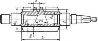
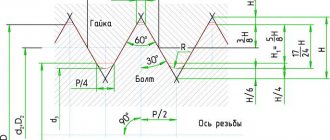
In Fig. Figure 4.46 shows a diagram of a worm gear, where is the profile angle of the worm (for Archimedean worms in the axial section, and for convolute and involute worms in the normal section).
Tooth height for Archimedean and convolute worms (– axial module for the worm and end module for the wheel); the height of the worm helix heads and worm wheel teeth; height of the legs of the worm helix and the tooth of the worm wheel
The pitch diameter of the worm, where is the coefficient of the diameter of the worm. When choosing, it is necessary to take into account that with its increase the efficiency decreases and decreases, and a decrease in q
reduces the bending strength of the worm.
Coefficient q
must be at least
Diameters of the tops and bottoms of the worm
Rice. 4.46
The main geometric parameters of the worm wheel are set in the middle section:
Pitch diameter of worm wheel:;
Diameters of the worm wheel peaks and valleys:
Largest wheel diameter:
Center distance:
– wheel circumference angle; – arc tooth width; – wheel width; when at
The angle of elevation of the worm coil is equal to the angle of inclination of the wheel teeth:
where is the step; is the number of worm passes.
When the worm gear operates in the contact zone, sliding occurs at high speeds, which causes a decrease in efficiency, wear and jamming. Sliding speed v
s is directed tangentially to the turn of the worm:
where is the peripheral rotation speed of the worm; – angle of elevation of the worm turn (see Fig. 4.45, c).
A worm with one go
The ability of a transmission to transmit movement from the driving link to the driven link, and when an external load is applied to the driven link, to fix its position without allowing it to move, is called self-braking
silt and irreversibility of movement. In a worm gear, irreversible motion occurs when no movement occurs when a load is applied to the worm wheel. Self-braking in a worm gear is associated with sliding friction. With a leading worm, the efficiency of a worm gear can be approximately determined as for a screw-nut transmission:
where is the reduced friction angle, is the reduced friction coefficient (depends on the roughness of the rubbing surfaces, the relative sliding speed of the worm and wheel turns, and the quality of the lubricant). For steel worm and bronze wheel at m/s; at m/s; at m/s.
Self-braking is possible when the angle of inclination of the worm turn is small. In this case, friction losses increase and efficiency () decreases significantly. High power transmission cannot be done in one pass () due to low efficiency and high heating. Non-self-braking worm gears have an efficiency of up to. With the increase and up to 27°, the transmission efficiency increases. Approximately for preliminary calculations of non-self-braking gears, the efficiency can be taken equal to at at at .
Forces in the worm gear. In the engagement of a worm pair, the total force can be decomposed into three components (Fig. 4.47):
Circumferential force on the wheel equal to the axial force on the worm:
The circumferential force on the worm is equal to the axial force on the wheel:
Radial force, where is the profile angle
Rice. 4.47
in the axial section of the worm; – torques on the worm and wheel.
The circumferential force on the driving worm is directed against rotation, and on the worm wheel - along the rotation.
Calculation of worm wheel teeth for strength. The main type of destruction of worm gears is associated with the destruction of the surface and wear of the bronze teeth of the worm wheels. The probability of tooth breakage is less, and the calculation of their bending strength is carried out as a test.
Similar to cylindrical gears, the teeth of worm wheels are checked for contact and bending strength. Calculation of the turns of a steel worm is not carried out, since they have greater strength than the bronze teeth of a worm wheel. For such worm gears, from the Hertz formula, an expression for test calculations for contact strength is obtained:
(4.66)
where is the design torque on the worm wheel, II ∙ m.
Permissible contact stresses for tin bronze BrОУФ1 MPa.
From formula (4.66) the expression for design calculations is obtained:
Test calculation of worm wheel teeth for bending is carried out according to the formula
(4.67)
where is the specific circumferential design force, N/mm; is the coefficient of the tooth shape of the worm wheel (see expressions (4.39)), where is the number of teeth of the equivalent wheel. Allowable bending stresses for bronzes MPa.
The worm wheel is calculated according to the parameters of an equivalent spur gear, in which the tooth length is equal to the arc width of the worm wheel tooth along the pitch circle. The body of the worm is tested for strength and rigidity as a rod of variable cross-section.
When operating a worm gear, especially one with low efficiency, most of the power loss due to friction results in the generation of heat. To satisfy the conditions of thermal balance (eliminate overheating of the gearbox), the cooling surface of the housing is increased by introducing fins, or additional cooling is used (blowing with a fan, using a circulating medium, etc.). To identify the possibility of overheating, a thermal calculation is made, and if necessary, measures are taken to ensure normal operation of the worm gear, preventing its overheating.
Worm gearboxes.
Typically gearboxes with a cast iron or steel housing are used. Recently,
Rice. 4.48
worm gearboxes appeared, the housing of which is made of aluminum alloy (for example, from ALZ).
Depending on the layout, gearboxes with a lower and upper, horizontal and vertical worm arrangement are used. The upper location is used at the peripheral speed of the worm m/s. Worm gearboxes must be capable of axial adjustment of the wheel to ensure good contact of the worm thread with the wheel tooth. If the worm gear is large, it is made of a composite wheel - a central part made of steel or cast iron and a rim with a gear ring made of bronze. A worm gearbox with a radial assembly and a horizontal worm arrangement is shown (in different projections) in Fig. 4.48, where 1
– worm,
2
– composite worm wheel. The position of the worm wheel is adjusted using K rings. Universal gearboxes are produced, which have three planes for its installation, and accordingly the worm can be with an upper or lower, horizontal or vertical arrangement.
The worm gear system consists of two components - the wheel and the worm itself. It is necessary in order to obtain rotation and transmit it between intersecting shafts (from one to the second), while reducing the speed and number of revolutions. The wheel works in conjunction with a worm, which can have a left-handed or right-handed thread, as well as single or multiple threads.
Basic data
A worm is a threaded screw that transmits its rotation to a helical wheel with arc-shaped teeth, causing it to rotate.
The teeth and turns of the screw are interlocked. The axes of the worm wheel shafts intersect at right angles, the screws intersect in the same plane and are mutually perpendicular.
The possibility of self-braking allows movement only from the worm to the wheel, otherwise braking may begin and a stop will occur.
The cutting screw is a hob cutter which is used in a worm wheel. Such cutters have different classifications (by processing, number of passes, etc.).
Worm wheel cutting
During design, a model of a worm wheel is created. Using it you can easily determine the cutting method:
The end one requires a tool that exactly replicates the worm. Gives good accuracy and cleanliness of processing. It is difficult to align the cutter, it is necessary that at the end of processing it has a position relative to the wheel that exactly corresponds to the worm.
Cutting teeth on the crown
The worm wheel has a semicircular recess along its outer diameter. This allows the parts to fit better along the involute and shift the axis, increasing the contact area. The center of the recess radius must coincide with the axis of the worm.
Worm wheel cutters must have the same outside diameter as the worm. Externally, it repeats the shape of the leading part, only instead of a continuous thread line there are rows of cutters. The cutting plate exactly matches the thread in shape, but is wider by the size of the gap. As a result, the configuration of the counter part - the worm wheel - exactly repeats the shape of the thread, the depressions coincide with the protrusions of the threads.
The cutter is aligned in the plane of the worm axis, touching its surface. The ring gear rotates around a vertical mandrel or its own shaft, providing tangential feed of the outer surface relative to the axis of the cutting tool. Worm wheel cutting occurs with the synchronous movement of the tool and the part rotating around their axes. The rotation speed ratio is determined by the gear ratio. With each revolution, the crown moves closer to the rotating cutter.
The cutting tool can be fed from below and from above. But in most cases, radial cutting is used as the most convenient and accurate.
Repair thread
Sometimes you need to make one part to replace it in the gearbox. The workshop does not always have a complete set of cutters with all normalized diameters.
If a worm wheel is cut with a cutter with a larger diameter than the radius of the worm, the fit will be worse and the contact patch will be smaller. The sliding line will move towards the top of the tooth. When cutting with a smaller diameter with the same module, the load will be on the top of the thread. The error can be compensated by shifting the tool and adjusting the distance between the axes. But friction and wear will still be greater, and efficiency will drop.
You can cut the worm wheel with a cutter with a diameter larger than the worm for backlash-free clutch. In this case, a special cutter is used with different profile angles for the right and left sides. The axis of the cutter is turned in the direction of increasing the inclination of the tooth. Conventional gear hobbing machines must be modified to machine backlash-free clutches.
Due to the lack of clearance between the working elements, the surface quickly wears out and you have to constantly make adjustments. Backlash-free clutches are used for high precision and high loads with low activity of the pair, for example, in rolling mills to adjust the roll pressure - the thickness of the rolled metal.
To manufacture one or several wheels with non-standard dimensions, a mandrel with one cutter in the shape of the cavity between the teeth can be used. The tool rotates constantly. The wheel rotates synchronously with the tool. After each revolution of the cut, it is rotated to the size of the tooth module and for a full revolution, it moves towards the mandrel with the cutter to the depth of the cut.
The disadvantage of the method of making a crown is the length of the process. One cutter processes a part several times longer than a milling cutter. Taking into account the abrasion of the cutter, it is necessary to do roughing and finishing.
The worm wheel differs from others in its appearance and processing method. It is done exactly for a specific worm.
Source
Varieties
The classification of worm gears is divided into two types: globoid gear worm wheels and cylindrical. The globoid version requires concentrated precision manufacturing and increased attention to cooling, and when worn, it reacts very subtly to axial movement of the screw. The cylindrical type has circular cylinders on the surfaces of the wheel and worm (initial and pitch).
Worm threads can have a trapezoidal thread in the axial section (the most popular type is Archimedes), the same profile, but in a normal section (convolute), involute (with a thread in the axial section similar to the name) or with a concave profile for maximum contact with the wheel.
Advantages and Benefits
The advantages include:
- quiet and smooth running due to a special coupling;
- reliable operation;
- small size and compact design;
- the possibility of reduction (obtaining large gear ratios) using one stage;
- self-braking or stopper, no possible reverse;
- ease of use and manufacture of worm wheels;
- low cost relative to other gearboxes (cylindrical).
As for which worm-type designs are often compared, their advantages include high efficiency, low-perceptible heating and insignificant play of the output shaft. They are just as reliable and have high performance; there is no independent stopper.
Several advantages of the worm gear should be highlighted
- smooth rotation during operation of the mechanism;
- high reliability with proper maintenance;
- small dimensions of the unit;
- affordable production price.
Both types of parts, a worm or a worm gear, can have design features depending on the necessary requirements.
A very important point is also the selection of a good grade of steel. The steel should be selected carbon or alloy, purchased from a reliable metal supplier with a certificate or quality passport. In the manufacture of a worm shaft, a steel circle (for small dimensions) or castings from forgings are used.
Flaws
The main disadvantages of a worm wheel include reduced power and restrictions on its transmission, a decrease in efficiency, as a result of which it is impossible to transfer heavy loads. Also, the manufacture of some parts requires strict adherence to precision, the use of expensive and rare materials, special lubricants, and in case of rapid wear or jamming, high-quality adjustments are important. The disadvantages may include an increase in the temperature of the housing and heating at the clutch, an increase in the backlash of the output shaft when the gearbox wears out.
From time to time it becomes necessary to reverse the output shaft without starting the gearbox. In this situation, stopping, which is considered an advantage of this type, becomes its disadvantage. Despite all the existing shortcomings in the form of increased heat generation and lack of power transfer, this transmission option is used in cases where there are no significant impact loads. This is a budget and relatively cheap option, which is used in mechanical engineering, mixers, conveyors and conveyors.
Worm gears are compared with cylindrical gears, which also have a number of disadvantages. They have a low gear ratio using a single gear.
Scope of application of the gearbox
This mechanism is an indispensable assistant in various fields of human activity. Typically it is used:
This mechanism is used very widely in industry. In various processing machines it is used as a rotary transmission part that increases the speed of rotation.
But in automobile gearboxes, the gearbox, on the contrary, reduces the engine speed. The smoothness and softness of the transport depends on how correctly its adjustment is done.
This speed-reducing device is also used in household appliances and electrical equipment with electric motors. These can be mixers, washing machines, drills, food processors, grinders.
Gearboxes are an indispensable part of ventilation equipment, treatment facilities, and pumping systems. They help maintain optimal gas pressure in gas-flame installations.
The gas production industry also cannot do without this mechanism. Transportation and storage of gases is a rather dangerous process, so a reducer is used to block the access of gas or open its outlet by adjusting the pressure.
Product design
As you know, a worm wheel is a gear consisting of two links: driven and driven, which work in conjunction. The main thing is a worm in the form of a screw, which sets the movement of the second element - the helical gear. It is along its teeth that the turns located on the screw slide. All together this is a gear-screw system. Most often, worm wheels are composite, this affects the cost, lowering it.
The worm is the leader, and most often reverse transmission is not possible because
this may cause the gearbox to brake. The teeth of the worm are longitudinally circular turns.
Archimedean screws are the most common type of worm in mechanical engineering. This option is in demand and easy to manufacture.
Standard options for worm wheels in mechanical engineering include bimetallic, banded and bolted designs. The first is often found in mass production.
How to make a worm gear with your own hands?
Home craftsmen try to equip their workshop with a variety of homemade devices that can make physical labor easier and improve the quality of work.
Such a useful device can be considered a reduction gearbox for a walk-behind tractor or mini tractor. This product is used to reduce the speed of the engine working shaft and increase its torque.
Before making a gearbox with your own hands, you should carefully study the instructions.
What is a gearbox
This device is a chain or gear mechanism located between the shaft of an electric motor or gasoline engine and the final assembly of the working apparatus.
The main technical characteristics of a reduction gearbox for a walk-behind tractor can be considered the following values:
- maximum transmitted power;
- efficiency;
- number of driven and driving working shafts.
It is worth noting that special worm or gear drives must be attached to the rotational units of the product.
This will help regulate and transmit rotation from one product to another . The frame contains through holes for bearings, with the help of which the side shafts rotate.
Where is the device used?
A reduction gearbox has many advantages. Its design allows you to increase the productivity and profit of large industrial enterprises. It can also be considered an indispensable assistant in the household.
Experts highlight the following areas of application of the device:
- in industry;
- in car gearboxes;
- in various electrical equipment.
At large enterprises this product is used quite widely. In various machines for metal processing, the gearbox is used as a rotary transmission unit, which increases the number of revolutions.
In gearboxes for automobile transport, a device is installed that reduces the engine speed. The softness and smooth running of the machine directly depends on the quality of adjustment of the gears of the gearbox.
This product is widely used in electrical equipment and household appliances, such as rotary hammers, drills or mixers.
Gearboxes can be considered the main parts of ventilation, planetary, pumping and cleaning systems, because they are able to maintain optimal operating pressure.
Manufacturing of the product body
Experts consider the body to be the most important part of the device.
The frame must be properly designed and assembled, because the position of the axes and working shafts, the alignment of the holes for the bearings, and the distance between the gears and belt mechanisms depend on it.
In the factory, housings for reduction gearboxes are made by casting from cast iron or aluminum alloys.
It is simply impossible to make such a blank on your own. For this reason, it is necessary to find or remodel the factory housing.
It can also be welded from iron sheet.
Some home craftsmen were able to find a simple way out of the situation. In order not to engage in boring work, it is necessary to completely weld the frame.
The support bearings will be installed in small sections of metal pipes.
They need to be placed in the working position, and then secured well with fastening materials or welding.
Experts advise making a special removable cover on the body for easy maintenance of structural components. It is worth making a drain hole at the bottom, which is necessary to drain the old oil.
DIY assembly
Experts say that making a small-sized worm gear with your own hands is quite troublesome, but it is possible.
The device should increase the torque of the working shaft of the walk-behind tractor and reduce its number of revolutions.
The maximum performance of the machine directly depends on the product.
The walk-behind tractor uses a reverse manual gearbox, which makes it possible to change speeds. The factory gear ratio is sometimes very small.
The designers equipped the unit with a small sprocket on the operating shaft of the gearbox.
Interacting with a large star from the wheel of the device, it ensures a decrease in engine speed.
An additional sprocket must be put on the working shaft located in the bearing platform. It will transmit torque through the second chain to the wheels of the walk-behind tractor.
Thus, you can assemble a reduction gearbox for an electric motor with your own hands, which will have high torque and a two-stage reduction in the number of engine revolutions.
Using a gearbox from any motorcycle, it becomes possible to adjust the speed without pressing the gas handle.
The engine will almost always operate at low speeds and fail less.
You can make a bevel gear with your own hands from an old scooter or tractor. In this case, the wheeled platform is not used .
Reduction gear, how to make a homemade one with your own hands, diagram of the device and operating principle of mechanical, gear and chain
We are looking for two authors for our site who are VERY well versed in the structure of modern cars. Contact by mail
Currently, many owners of home workshops equip them with modern tools and equipment, which, being highly efficient and easy to use, significantly facilitates work and increases its productivity. However, at the same time, quite technically simple devices that can be made with your own hands in a home workshop are still in demand. One of them is a reduction gearbox.
What is a reduction gearbox?
It is a special type of mechanism that serves as a transmission link between devices in which the active parts perform rotational motion.
It is often used to transmit and convert torque from the unit that produces it to the device that uses the mechanical energy supplied to it. Unlike other types, a reduction gearbox provides a reduction in the number of revolutions and an increase in torque.
Toothed gears are located on the shafts in a rigid coupling, and worm gears are attached. They ensure the transfer of motion to each other, during which its transformation is carried out.
Kinds
There are different types of reduction gearboxes:
- gear;
- worm;
- combined.
In addition, they are:
- single-stage;
- multi-stage.
Basic indicators
- efficiency;
- transmission power;
- number of rotations of the driven and drive shafts.
The reduction gear has a fairly simple design, so if you have the appropriate spare parts and materials, you can make it in a home workshop with your own hands.
Preliminary preparation
Before you begin creating this device, you must have general knowledge of mechanics, be able to use repair tools and equipment, and know the operating principle and structure of this unit.
In addition, you need to initially determine:
- the type of future gearbox and its version;
- the gear ratio that will need to be converted and determined at the output;
- indicators of dynamic loads that will affect the working parts of the device;
- weight and dimensions of the future device;
- installation angle;
- temperature limits that will occur in the device during its operation;
- switching cycle – full or variable;
- intensity of operation.
Parts and parts of the reduction gearbox
- Drive and driven shafts;
- Bearings suitable in diameter for axles and shafts;
- Sets of sprockets of a certain size with a certain number of teeth;
- Torque transmission chains;
- Sheet steel;
- Corner profile;
- Frame.
More details about the components
The assembly process is not as complicated as the selection or production of spare parts necessary for such a gearbox.
- Device body. In industry it is produced by casting. The necessary holes are made using high-precision equipment, since it is necessary to achieve the mutually correct arrangement of the shafts and the alignment of the stars. When producing it, it is necessary to make the top cover removable. This will facilitate and simplify the process of servicing it during operation;
- Shafts and axles of the gearbox. They support gears and are used if they need to be equipped with this device. Installation is carried out by pressing onto splines or keys. For their manufacture, it is better to use durable steel measuring from 10 to 45 mm, which is easy to machine;
- Bearings. They are used as supports for shafts and resist loads and provide the possibility of rotational movement. Its reliability, durability and performance depend on the correct selection of these gearbox elements. If you are installing spur gears, then it will be sufficient to install conventional single or double row ball bearings. If a helical bearing or worm gear will be installed, then a roller or angular thrust ball bearing will be the best option. It is better to buy new ones than to use them from disassembly;
- Gears. They provide a change in the rotation speed of the shafts and, naturally, a reduction in the gear ratio. For their production, special metal-cutting equipment is used, which home workshops are not equipped with. The dimensions and characteristics of other parts included in this unit, as well as the distance between the axles and shafts, depend on the size of the gears. When installing, it is important to correctly set the gap between them. I-20 oil is perfect for lubricating gears. It is filled to the level of the bottom of the gears. Other parts of the device are lubricated by spraying lubricant onto them. You can take it from disassembly or buy new ones;
- Oil seals. They prevent oil from leaking out of the device body. They are installed at the exit points of the shafts on bearings under the covers. Are bought;
- Safety coupling. It is designed to prevent destruction of the device when excessive loads occur. Buyable;
- Bearing caps. They can be different - deaf and through. Designed to facilitate maintenance and installation of bearings. You can grind them yourself or find them at a disassembly site.
Materials used
For the manufacture of worm wheels, specialized ones are used that prevent jamming and jamming, promote long-term operation and resistance to wear, and affect the coefficient of friction, reducing and reducing it.
If all materials are selected correctly, the efficiency increases, and friction does not cause additional costs.
Various materials and alloys are used for links: for the screw - steel, paying special attention to the grade of material and its hardening. Most often, the screw is solid, combined with the shaft. From time to time there are mounted options.
In the manufacture of wheels, bronze is used, as well as alloys of tin and nickel, aluminum and iron. It is possible to use cast iron and brass for the ring gear. Often the wheel has a steel or cast iron hub. Wheels are cast using the centrifugal method.
How to make a worm shaft?
as well as the necessary requirements, advantages and disadvantages of the operation of worm shafts in mechanisms
The need for worm shafts exists in various fields of activity, for example in the automotive industry, the production of various special equipment, drilling stations, lifting mechanisms and much more. The most important criterion in the manufacture of a worm shaft is accuracy and adherence to technological measures. Because the advantage of the mechanism is the accuracy in the transmission of torque. If accuracy is not maintained, the risk of increased noise during operation, rapid wear of the part and jamming of the worm pair increases.
Forms and types
Screws are divided into left and right, depending on the location and direction of the turns. In the first case, the screw is unscrewed in a clockwise direction. In the second case, moving in the same direction, the screw is screwed in. These changes can be seen when tracking movement from the end of the screw.
The screw can have one or many turns (ridges), which, depending on the number, are placed on a helical line located on the index cylinder. This characterizes the number of turns of the screw.
The worm can be located on top, below or to the side of the wheel, thus changing the shape of the gear.
The worm wheel shaft can be horizontal or vertical.
The surface and profile of the screw thread may also differ, while several transmission options are possible, each with its own cutting method (with a convolute, involute, Archimedean screw).
In addition, there may be differences in worm wheels depending on the shape of the surface of the screw on which its thread is formed (cylindrical or globoid screw). In the second case, the transmission has a higher efficiency, but is difficult to create and release; a distinctive feature of the formation is a circular arc. In the first version, the distinguishing feature is a straight line that forms the dividing surface.
The worm wheel is the main part of the worm gear, which includes the wheel and screw. These two links are a worm pair that interacts with each other according to the screw principle. Gearboxes are manufactured on its basis. The product has a low efficiency, but is easy to manufacture and use.
We looked at what a worm wheel is, highlighted the main advantages and disadvantages, and indicated the materials of production and scope of application.
A worm gear is a small gear-screw mechanism that moves according to the principle of a screw pair. This device is used to transmit rotational forces between shafts, the crossing angle of which is 90 degrees.
Design
The worm gear gets its name from the driving part that transmits torque. The driven part has a tooth with an oblique cut. Along the rim there is a radial understatement of the surface. This increases the line of contact between the thread and the tooth.
The rotation axes of the parts are located at an angle. Usually it is 90°, but can be 45°. This arrangement of parts is used in heavily loaded low-speed gears, with a point speed on the outer surface of less than 5 m/sec.
When the gear interacts, the thread surface does not push the teeth in the direction of rotation, but slides along the involute, as if pushing it aside. As a result, strong friction and heating of parts at the point of contact occurs.
The worm pair must be well lubricated, cooled and have anti-friction properties. The material of the worm cannot be changed; it is cut from chromium steel and undergoes hardening, grinding of the thread surface or sugaring - processing with a plate with a shallow depth of cut. The tool pushes the surface of the thread rather than cutting it. A hardening is created on the top layer, strengthening the working surface and making it smooth.
Material for the crown
The gear ring is made of a relatively soft material with high abrasion resistance. Tin bronze and brass are mainly used. For low-speed manual transmissions, the crown can be made of gray cast iron. Depending on the rotation speed, the ring gear is made of the following material:
Bronze is much more expensive than steel and is softer. Parts are made entirely from it, the dimensions of which are within 160 mm. Large parts are machined from steel and only the crown is bronze. It is hot seated on the shaft and secured with pins along the connection line so that the crown does not rotate. After cooling, the wheel is finished and the tooth is cut.
Diameter calculation
The diameter of the wheel is calculated along the centerline of the tooth - the width of the tooth and the cavity are equal. The outer radius used for manufacturing and calculations is determined theoretically. Once the processing is completed, it is located outside the actual wheel rim.
Sliding occurs along the line of the pitch diameter - the middle of the tooth in height. It is calculated by the formula:
where d2 is the pitch diameter of the gear; m – module; z2 – number of wheel teeth.
The outer radius of the tooth has one center with the axis of the worm.
Ring gear width
The width of the worm wheel crown is determined by the number of turns of the screw using the formula:
where b2 is the width of the crown; 0.315 and 0.355 – calculated coefficient; Z1 – number of screw thread starts; a – center-to-center distance; aw is the distance taking into account the displacement of the worm relative to the gear.
The offset distance determines the size of the gap between the working elements of the parts.
Advantages and disadvantages of this mechanism
Worm gear motors and other devices made using this technology are distinguished by their silent and at the same time smooth operation. Also, these devices are very compact in size, due to which they have a relatively low structural weight. The worm gear motor is distinguished by its ability to achieve large reductions - the property of obtaining high gear ratios. This device also has high kinematic accuracy. However, its main disadvantage is its relatively low efficiency. This characteristic is formed due to the sliding of the turns of the worm screw along the teeth of the device wheel. Also, the worm gear has a high tendency to jam, as a result of which the device of this mechanism cannot boast of its reliability and long service life.
Worm-gear
This pair has a special design that does not allow it to rotate in the opposite direction. It has a special operating principle and is used in gearboxes, as it has a very high gear ratio (from 5:1 to 300:1).
The pair is made so that the worm can turn the gear, but not vice versa.
The coil has a gentle lift angle, this holds the wheel in place during traction. They are often installed on conveyor belts. Blocking reverse movement in this case plays the role of a kind of brake and emergency stop. SEE ALSO: Production of laser machines • CNC laser machines • How to choose a laser machine
Application
If we talk about the automotive industry, this transmission is most often installed on trolleybuses. In addition, it is widely in demand in the industrial sector. Worm gears are used in many machine tools and material handling machines. Typically, the scope of application of this device is limited to devices with a rated power of less than 100 kW. It is not used on more powerful tools due to low efficiency and frequent heating during operation, which would require the use of additional cooling systems.
Application of the mechanism
The worm gear is capable of replacing a multi-stage gearbox with small dimensions. Its gear ratio is determined by the value 100; in individual nodes it can be significantly higher.
The use of a worm gear is advisable in mechanisms that require high precision at low speed:
Self-braking and precision movement are mainly used.
Materials for production
Finally, some information about what materials are used in the production of worm gears. Screws for these devices are most often made of high-strength alloy or carbon steel. In addition, during production the worms of this mechanism are subjected to heat treatment, which significantly increases the strength of the device. At the final stages after hardening, the steel is sent for grinding. When it comes to ring gears, they can be made from several materials. Whether it will be bronze, brass or cast iron depends on the anti-friction properties of the device. By the way, each of the above materials is used on worms at a certain sliding speed. For example, cast iron is used at speed VS
Worm (or gear-screw) gear
(Fig. 180) is a kinematic pair consisting of a worm and a worm wheel. Worm gears are used to transmit rotation between shafts whose axes intersect at an angle of 90°.
Rice. 180
The leading link is usually the worm. Reverse transmission is rare because it has very low efficiency.
Worm
- this is a screw with a thread cut on a cylinder (Archimedes, convolute or involute worm - Fig. 180, I) or globoid (Fig. 180, II). The Archimedes worm is a cylindrical screw with a trapezoidal thread profile. In the end section, the turns of this worm are outlined by an Archimedean spiral. A globoid worm is a screw cut into the surface of a torus (globoid). A transmission with such a worm is called globoid. Worm elements are similar to thread elements.
Worm wheels
They come with straight and more often with oblique teeth and differ from cylindrical gears in several modifications in the shape of the tooth. The tooth of the worm wheel covers the worm in an arc limited by an angle of 2 y, which is chosen within 90 ... 110 °. The elements of a worm wheel are basically the same as those of a spur gear.
Worm gears make it possible to obtain large gear ratios (up to 300, and sometimes more); provide smooth engagement, are compact and silent in operation. The disadvantages of a worm gear include relatively low efficiency; strong heating during prolonged operation and, as a result, rapid wear of elements; high cost of material (bronze) of the worm wheel, etc.
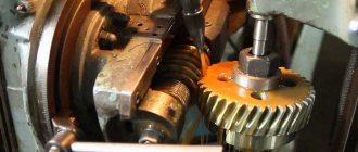
In Fig. 181, where: 1 — handle for turning the rack and pinion mechanism on and off; 2 - gear wheel sitting on the roller-wheel; 3 - toothed roller-wheel rolling along the rack; 4 - gear wheel moving along the splined shaft; 5 - worm wheel; 6 - uterine nut; 7 — gear rack; 8 — lead screw; 9 — running roller; 10 — handle of the uterine nut; 11 - worm; 12 — handle for mechanical feed of the caliper; 13 - longitudinal feed flywheel, the apron mechanism of a lathe is given as an example.
Rice. 181
content .. 11 12 173.3.
Manufacturing of cylindrical worm gears
The most common types of worms in cylindrical worm gears are the following (GOST 18498 - 73): Archimedean (ZA), involute (ZI),
convolute with straight helix profiles (ZN1), convolute with rectilinear cavity profiles (ZN2), convolute with a straight normal helix profile (ZN3) and formed by a cone (ZK1) and (ZK2).
In recent years, transmissions with worms have been used, the turns of which in the normal section have profiles in the shape of a circular arc - cylindrical worms formed by a torus (ZT1).
The geometry of each of these types of worms is associated with its own technological methods.
Depending on the scale of production and hardness, cutting turns of cylindrical worms can be done in various ways. In single and small-scale production, worms that are not subjected to heat treatment or heat-treated to a hardness of HRCe 38 are cut with profile cutters, disk or finger cutters, and in serial and mass production - by a vortex method or plastic deformation. For worms hardened to a hardness of HRCe 51 or more, the finishing operation for processing the working surfaces of the turns is grinding.
The main technological feature of the geometry of cylindrical worm gears, which distinguishes them from other types of gears, is that the producing surfaces (producing worm) of the tool when cutting the teeth of a worm wheel using the rolling method must coincide or in a certain way differ slightly from the working surfaces of the worm itself. As such a tool, hob cutters are usually used, which are a cylindrical worm, the turns of which are intersected by helical grooves to form cutting edges, and the side surfaces and surfaces of the apexes have backs to form rear cutting angles. The cutting edges of the cutter must lie on the imaginary surface of the worm of the required type.
The worms and worm wheels themselves, before the formation of the gearing elements, are bodies of rotation and conventional processing methods are used in their manufacture.
Processing of threads of cylindrical worms
Cutting cylindrical worms with profile cutters
on lathes
The Archimedes worm ZA has a rectilinear coil profile in the axial section AA (Fig. 3.4) and a curved profile in the normal section. The end section of the coil is an Archimedean spiral. The involute worm Z1 has a rectilinear coil profile in the section with a plane tangent to the main cylinder, and a curved profile in the normal section; the end section is an involute. The coil of the convolute worm ZN1 has a rectilinear profile in the explosive section ,
perpendicular to the turn, the turn of the worm ZN2 is in the section BB
,
perpendicular to the cavity, and the turn of the worm ZN3 is in the sections GG
,
perpendicular to the lines of the turn. All convolute worms have a curved coil profile in the axial section AA, and an elongated or shortened involute in the end section.
Rice. 3.4. Sections of cylindrical worms: AA - axial, BB - section normal to the cavity; BB - section normal to the turn; GG —
section normal to the coil lines
The most technologically advanced worms are ZA, the processing of which on a lathe is practically no different from the processing of screws with trapezoidal threads. The cutter is installed so that its cutting edges lie in the axial plane of the worm. The installation of a double-sided cutter with a straight profile is shown in Fig. 3.5. This method of cutting a helix can only be recommended for worms with a small helix angle due to the difference in cutting conditions on the left and right sides. For finishing cutting of ZA worms with a helix line elevation angle of up to 10°, it is recommended to separately process the left and right sides of the helix with single-sided cutters.
The installation of single-sided cutters is shown in Fig. 3.6. When cutting worm turns with a one-sided cutter, it is possible to alternately process both sides of the cavity with one cutter by turning the worm.
| Rice. 3.5. Installation diagram of a double-sided cutter when cutting a ZA worm | Rice. 3.6. Scheme for installing one-sided cutters when cutting a ZA worm |
The cutter installation diagram for cutting worms of type ZN1 and ZN2 is shown in Fig. 3.7, 3.8.
Convolute worms (ZN1 and ZN2) are cleanly cut with one or two cutters with straight cutting edges, located for the ZN1 worm (Fig. 3.7) in the normal section of the turn and for the ZN2 worm (Fig. 3.8) in the normal section of the cavity. The angles of the coil profile anT and in the normal section of the cavity anS according to GOST 19036 - 73 are assumed to be the same, equal to 20°.
The installation of the cutter for cutting a coil of a ZN3 worm with a straight profile in a section normal to the profile is the same as for cutting the coils of a ZN2 worm.
| Rice. 3.7. Diagram of installation of cutters for cutting a coil of a ZN1 worm (with a straight profile in a section normal to the coil) | Rice. 3.8. Installation diagram of a double-sided cutter for cutting a coil of a ZN2 worm (with a straight profile in a section normal to the cavity) |
When cutting an involute worm ZI, cutters having a straight profile are installed so that the horizontal plane passing through the cutting edge is tangent to the main cylinder. The installation of cutters when cutting involute worms is shown in Fig. 3.9, 3.10.
| Rice. 3.9. Installation diagram of cutters for cutting the right worm ZI | Rice. 3.10. Installation diagram of cutters for cutting the left wormZI |
Cutting cylindrical worms using milling method
Milling is carried out on thread milling, gear hobbing or special machines for milling worms. Disc or finger cutters are used as tools. Milling is a more productive operation than cutting with cutters.
Disc cutters for preliminary cutting of all types of worms are made with a trapezoidal profile. For finishing milling or for grinding turns, each standard size of worm must correspond to a special cutter with curved cutting edges.
Cutting worms with disc cutters is mainly used for rough milling of worm turns, worms no more precise than the 9th degree of accuracy.
In the case of using disk cutters with straight cutting edges and the location of the cutter axis at an angle g (Fig. 3.11) to the worm axis, only ZK1 type worms, in which the generatrices of the helical surfaces are not straight lines, can be completely milled.
| Rice. 3.11. Diagram of installation of a disk cutter when cutting cylindrical worms |
To facilitate the production of ZI and ZN worms, it is allowed to use cutters with a straight profile, provided that the resulting error in the worm profile is less than the tolerance left for finishing.
The milling method is used to pre-process worm turns with concave profiles of the type ZT1 (cylindrical worms formed by a torus, the axis of which is crossed with the axis of the producing torus at an angle equal to the pitch angle of the worm's turn), ZT2 (cylindrical worms formed by a torus, the axis of which is crossed with the axis of the producing torus at an angle at which one of the flat sections of the main surface of the worm is an arc of a circle coinciding with the generatrix of the generating torus).
The tool used is a disk cutter with a mountain-shaped surface.
Finger cutters are used for milling turns of large worms when it is not possible to use any other tool.
Gearing with rolling cutters (vortex cutting of turns)
This method consists of cutting worms by turning with continuous rolling. The tool used is a spur or helical involute cutting wheel (resembling a gear cutter). There is a forced kinematic connection between the rotation of the worm and the cutter. Feed during cutting occurs due to the axial movement of the worm workpiece (or a support with a cutter) with synchronous additional rotation of the cutter (Fig. 3.12). Cutting worms using the gear turning method can be done on special machines (model EZ-10A) or gear hobbing machines with a tangential feed feed. Depending on the geometry and sharpening of the cutter, as well as on the relative position of the worm and cutter, worms with different geometries can be processed (Archimedean, convolute, involute).
| Rice. 3.12. Cutting a worm using the tooth turning method |
For worms subjected to heat treatment, cutting is a preliminary operation performed with an allowance for grinding.
Rolling turns of the worm.
Rolling is the most productive and least material-intensive processing method. Rolling is carried out on roller rolling machines (mills). Worms with m < 3 mm are rolled on two-roller machines in a cold state, and with m ³ 3 mm - on three-roller machines, usually heating the workpiece using high-frequency heat. The schematic diagram of rolling machines is shown in Fig. 3.13.
| A ) | b ) | |
| Rice. 3.13. Schematic diagrams of machines for rolling worms: A ) - three-roll; 2 - movable roller; 3 — supporting knife; 4 - stationary roller | ||
Deviations in dimensions (mm) of screw surfaces of worms obtained by cold rolling (m = 1...2 mm) are as follows:
By step………………………………………………………………………………….0.015
According to the thickness of the tooth at the pitch diameter………………………….0.02 - 0.03
According to the radial runout of the worm coil relative to the axis of the centers...0.1 - 0.25
According to fluctuations in the diameter of the depressions……………………………………………..0.05
If the center holes are processed after rolling, basing the workpiece on the working profiles, then the radial runout can be reduced to 0.04 - 0.08 mm. Thus, by cold rolling it is possible to obtain worms corresponding to the 8th degree of accuracy, and for certain parameters - to the 7th degree of accuracy.
The deviations in dimensions (mm) of the helical surfaces of worms obtained by hot rolling are as follows:
By step………………………………………………………………………………… 0.03 - 0.05
According to the thickness of the tooth at the pitch diameter…………………………. 0.03 - 0.05
According to the radial runout of the worm turn relative to the axis of the centers....0.3 - 0.8
According to fluctuations in the diameter of the vertices, no more than……………………………………0.4
According to fluctuations in the diameter of the depressions at m < 5 mm, no more than………………………0.1
Grinding the side surfaces of the worm turns
Grinding of turns of Archimedean, involute and convolute worms is usually done with disk wheels with curved generatrices of the cutting part, obtained by dressing the wheels with a special device. In this case, the axis of the circle makes an angle g with the axis of the grinding worm (Fig. 14).
| Rice. 3.14. Installing a disc grinding wheel for double-sided grinding |
For ZA cylindrical worms, only worms of the 8-9th degree of accuracy can be grinded with a disk wheel with a straight generatrix due to significant distortions of the profile.
A feature of the geometry of involute worms is the possibility of grinding their turns with circles with straight generatrices of conical surfaces coinciding with the generatrices of the helical surface of the involute worm (Fig. 3.15). With this grinding scheme, the axis of the wheel is parallel to the axis of the worm.
| Rice. 3.15. Installing a disc grinding wheel when grinding an involute worm with one side |
In Fig. Figure 3.16 shows a diagram of grinding an involute worm forming the cone of a cup wheel. Each side of the coil is ground separately when installing the wheel. When grinding the turns of an involute worm using the end plane of a wheel, each side of the turn is ground separately. The end plane of the wheel with this grinding scheme must lie in the plane, which represents the side of the tooth of an imaginary rack that engages with the involute screw.
| Rice. 3.16. Scheme of installation of a cup grinding wheel when grinding involute worms: db - diameter of the main cylinder of the worm; gb is the helix angle on the main cylinder; a0 is the angle between the base and the conical part of the circle |
In Fig. Figure 3.17 shows a diagram of grinding an Archimedean worm with a cup-cone wheel. Grinding with a cup cone wheel with a straight cone generatrix makes it possible to ensure profile accuracy within the 8th - 9th degree of accuracy.
When grinding with a cup wheel with a straight generatrix of the conical part of the wheel, the profile of the coil is closer to the Archimedean spiral than when grinding with a disk wheel. To obtain an accurate profile of the grinding worm, the grinding wheel must be dressed along a curve.
| Rice. 3.17. Installing a cup wheel when grinding Archimedean worms: a is the angle of the axial profile; a2—grinding wheel angle; grot - angle of rotation around the generatrix |
Large-module Archimedean and convolute worms (m > 25) are ground with finger profile wheels, which ensures the 8-9th degree of accuracy (Fig. 3.18).
| Rice. 3.18. Installation of the finger circle |
The amount of allowance for grinding the side surfaces of the turns is given in table. 3.1. Large allowances according to the table are prescribed for less rigid worms, as well as in cases where significant deformations are possible during mechanical or heat treatment: for worms that have grooves for tool exit; for worms, the lateral surfaces of the turns of which are obtained by plastic deformation methods; for worms with increased distances between bearings or subjected to repeated heat treatment, etc.
Table 3.1
The amount of allowance for grinding the side surfaces of turns of cylindrical worms (per side), mm
| Module m, mm | Diameter of projections da 1, mm | ||||
| Up to 22 | 22 — 36 | 37 — 71 | 71 — 110 | St. 110 | |
| Up to 2 | 0,1 — 0,15 | 0,15 — 0,20 | 0,18 — 0,25 | — | — |
| 2 — 4 | 0,15 — 0,20 | 0,02 — 0,25 | 0,25 — 0,30 | 0,28 — 0,35 | — |
| 4 — 6 | — | 0,22 — 0,30 | 0,25 — 0,32 | 0,30 — 0,40 | 0,32 — 0,45 |
| 6 — 8 | — | — | 0,28 — 0,35 | 0,32 — 0,42 | 0,40 — 0,50 |
| 8 — 10 | — | — | 0,30 — 0,40 | 0,35 — 0,48 | 0,42 — 0,60 |
In the manufacture of precision worms, after preliminary cutting, before carburizing and hardening, the first grinding of the turns is carried out, which ensures a minimum and uniform allowance for subsequent operations. After heat treatment, several grinding operations are performed with intermediate restoration of the technological bases and removal of residual stresses by keeping the worm for several hours in a heated oil bath. Final grinding is carried out under constant temperature conditions using precision equipment.
Lapping and polishing the worm
To reduce the surface roughness of the coils, the worms are ground in and polished. Lapping is carried out on special or universal lathes. A cast iron or textolite worm wheel is used as a lap, mounted on an axis fixed in the machine support and engaged with a rotating worm. To process turns along the entire length of the worm, the caliper must perform a reciprocating movement along the worm. The lapping is slightly slowed down by a special device, and an abrasive mixture is supplied to the engagement zone, which includes: electrocorundum with a grain size of 5 - 32 (4%), crocus (4%), paraffin (2%) and machine oil (90%). Metal removal during grinding should not exceed 0.01 - 0.02 mm. Processing time 2 - 5 minutes. The lapping process should not be used to correct errors in the profile and pitch of worms.
The worm turns of heavily loaded gears are polished to achieve a minimum unevenness height. Polishing is carried out with a rapidly rotating felt or felt wheel coated with polishing paste. The felt circle is forced to move along the helical groove of a slowly rotating worm. Final polishing is carried out using a cloth wheel with polishing paste.
Cutting worm gear teeth
The processing of worm wheels before the gear cutting operation does not have any fundamental specificity compared to the processing of conventional round parts of a similar class.
Two methods are used for cutting the teeth of worm wheels on gear hobbing machines:
1) hob cutters with radial or axial tool feed;
2) flying cutters or multi-tooth cutters with axial feed.
In both methods, the cutting edges of the tool must reproduce in space the surface of the producing worm, which is in engagement with the worm wheel being cut at the same center-to-center distance as with the working worm.
The difference between a nominal tool producing worm and a working one is the increase (by double the radial clearance) in the diameter of the vertices and the guaranteed lateral clearance of the thickness of the turns. In addition, the tool worm must have rounded turns to form transitional curves at the base of the teeth of the worm wheel being cut.
Cutting the teeth of worm wheels with hobs
When cutting wheels with hobs, the axial feed method is preferable, since the radial feed method does not ensure complete processing of the tooth surfaces and at the same time can lead to excessive cutting of sections of the working surfaces of the latter. With radial feed, the side surfaces of the teeth usually acquire a cut with a number of edges equal to the number of cutting teeth of the cutter along the length of the normal pitch of the worm.
In a transmission with worm wheels cut by radial feed, it is almost impossible to ensure the required accuracy according to contact standards. Such gears require long-term running-in, are not capable of bearing the rated load, and are prone to jamming.
Cutting is carried out with a milling cutter while gradually reducing the machine center distance between the tool and the workpiece. The method is the most productive compared to others and is used in both mass and serial production (in single production, cutting is done with a cutter), and ensures cutting of wheels with 8th degree of accuracy. When cutting wheels with multi-turn cutters, it is necessary that the number of teeth of the wheel being cut and the number of turns of the cutter do not have common factors, and also that the number of grooves of the cutter is not a multiple of the number of turns.
Cutting is performed at a constant interaxial distance, and the tool feed movement is performed by moving it along the axis. With this feeding method, greater profile accuracy is achieved than with the radial one; it depends only on the feed amount.
The appearance of a hob cutter for working using the radial feed method is shown in Fig. 3.19 a,
and for working using the axial feed method - in Fig. 3.19
b
.
With the axial feed of cutters, which also have a small number of cutting teeth along the normal pitch length, the cutting of the side surfaces of the wheel teeth depends on the axial feed of the cutter per revolution of the wheel and is usually practically not noticeable.
| A ) | ||
| b) | ||
| Rice. 3.19. Hob cutter for cutting worm wheels | ||
To unload the cutting teeth, which, during axial feed, are the first to cut into the wheel, the intake part of the cutter is made conical (Fig. 3.19 b
). The intake part is followed by a cylindrical section, the teeth of which form the surface of the wheel teeth. Cutters with a fence cone have increased resistance and durability. To increase the durability of finishing tools in mass production, wheels are pre-cut using milling cutters with thinned turns using the radial feed method and finishing using cutters with axial feed.
Cutting worm wheel teeth with cutters
In the manufacture of especially large worm gears, as well as in individual and small-scale production, when there is no practicality in manufacturing hob cutters for cutting worm wheels, flying cutters can be used (Fig. 3.20) or, for multi-start worms, cutting heads (Fig. 3.21). In this case, to completely form the lateral surfaces of the teeth, you can use only the axial feed of the tool with its movement from the beginning to the complete end of cutting. Therefore, it is necessary to have such a length of the mandrel in which the cutter is installed to ensure the required length of pulling of the cutter. The shape and position of the cutting edges of the cutters must correspond to the position and shape of the generatrices of the helical surface of the worm that engages with the wheel being cut.
Thus, with Archimedean worms (ZA), the cutting edges of the cutter are located in the axial plane of the cutter mandrel, with convolute worms in the plane normal to the turn or cavity.
| Rice. 3.20. Flying cutter mandrel |
| Rice. 3.21. Cutting head (three-tooth incisor) |
Worm wheels of large modules are sequentially processed by several cutters (Fig. 3.22).
| Rice. 3.22. Scheme of cutting worm wheels with four cutters |
Shearing of worm wheel teeth
Shearing the teeth of worm wheels is a finishing operation and is used for wheels of the 6th degree of accuracy and more accurate. Shewing is carried out after finishing milling.
A worm gear is a worm whose surface geometry completely coincides with the geometry of the working worm’s turns. The shaver acquires its cutting properties due to the large number of small radial grooves present on the surface of the coils.
Shearing can be performed in two ways: radial feed movement with backlash-free engagement (approaching to the nominal center distance) and circumferential feed movement. In both cases, the wheel rotates by rotating the shaver cutter (the table drive mechanism does not work).
When shaving using the radial feed movement method, the shaver must have a coil thickness equal to the width of the wheel cavity. When moving the wheel using a circular feed motion, the tooth of the shaver must engage with the wheel with a gap if the nominal center distance is set. Shaving of the profile occurs due to the fact that the shaver cutter leads (rotates) the wheel blank, which in some cases is braked. After processing one side, the direction of rotation of the shaver changes and shaving is performed by the other part of the shaver, which has the opposite direction of the teeth (notches).
Sometimes in the practice of cutting wheels for precision gears, a very expensive tool is used, which is a milling cutter for axial feed, which goes directly into the shaver and even into the lap. The allowance for the thickness of the worm wheel teeth for finishing cutting with hob cutters is taken to be 0.lm and for shaving 0.03 m.
content .. 11 12 17