Drilling, countersinking and reaming
TO
category:
Drilling metal
Drilling, countersinking and reaming
Next: Metal Milling
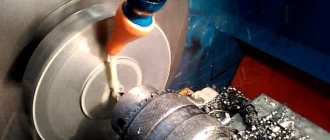
Drilling, countersinking and reaming are carried out on various types of drilling machines, aggregate boring machines, as well as turning machines. In addition, these operations can be performed using hand and mechanical drills.
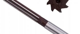
Drilling. Drilling is a machining operation to produce holes in a solid material. Drills of various designs are used as cutting tools for drilling. The main movement when drilling is rotational, the feed movement is translational. On general purpose drilling machines and boring machines, the main movement is the drill; on lathes and special drilling machines for deep drilling, the drill has only translational motion, and the workpiece has rotational motion; this determines higher processing accuracy.
Rice. 1. Twist drill
During drill operation, the transverse edge does not cut, but presses the metal of the workpiece. It was found that about 65% of the feed force occurs at the transverse edge.
Rice. 2. Double sharpening of twist drill
To facilitate the working conditions of the drill, the transverse edge is sharpened. For the same purpose, drills working on cast iron and steel are double sharpened with an angle of 2 ft! = 75-80°. The width b of the rear surface of the second sharpening is made within 0.18-0.22 of the drill diameter. As a result of double sharpening, the width of the chip increases at the expense of the thickness, the leading angle decreases, and therefore the durability of the drill increases.
Centering drills are used for drilling center holes when centering workpieces. These drills are made combined and double-sided for better use of tool steel.
Feather drills are made in the form of blades. They are rarely used, mainly when drilling holes in hard forgings and castings.
Drills with carbide inserts are manufactured with a diameter of 3 to 50 mm and are used for drilling bleached cast iron, hard steels, etc.
Deep holes are defined as holes having a length five times or more greater than their diameter.
Drills for deep drilling are manufactured with a diameter of 6 to 100 mm. Drilling holes with such drills is carried out on special drilling machines, and in most cases, only the feed movement is communicated to the drill, and the main movement (rotational) is transmitted to the workpiece.
Rice. 3. Center drill
Rice. 4. Feather drill
Rice. 5. Drill with carbide insert
In Fig. 6 shows a gun drill made from a round rod. The cutting edge of the drill is formed by the front surface and the rear surface (unilateral cutting).
Rice. 6. Gun drill
Rice. 7. Gun drill
Rice. 8. Countersinking scheme
In addition to gun drills, the following are used for drilling deep holes: a) gun drills for drilling holes of small diameter and great depth. These drills are hollow inside (to supply coolant) and have a groove to drain the liquid along with the chips; b) single- and double-cut drills for drilling deep holes of medium and large diameters; c) heads for circular drilling of deep holes of large diameter. Qi.nozny drilling of metal with diameters over 100 mm is unprofitable, therefore, in such cases, hollow drilling heads with cutters fixed in them are used.
Countersinking. Countersinking is a machining operation by cutting the walls or inlet of a hole; countersinking is carried out using holes obtained during casting or forging (black) or pre-drilled holes. The purpose of countersinking is to obtain more accurate dimensions of holes and the position of their axes, shaped processing of the end (input) part of the hole to obtain recesses for screw heads, etc.
The cutting process during countersinking is similar to the simultaneous operation of several boring cutters, which in this case can be considered countersink teeth.
There are four main types of countersinks: for expanding holes, for producing cylindrical recesses of holes, for producing conical recesses for holes, for cleaning end surfaces.
Countersinks for expanding holes are made three-pronged (for holes up to 30 mm) and four-pronged (for holes up to 100 mm). In Fig. 9, a shows a three-tooth countersink with a conical shank for mounting in the machine spindle, and in Fig. 281, b - four-tooth mounted countersink. In order to increase productivity, countersinks are equipped with plates made of hard alloys.
In addition to solid countersinks, countersinks with inserted knives made of high-speed steel or reinforced carbide alloys are also produced. The advantage of such countersinks is the saving of high-speed steel and the ability to regulate the processing diameter. Mounted countersinks with insert knives can have 6 teeth -
Processing with countersinks ensures correction of the axis with holes, increases accuracy to 4-5 classes and surface cleanliness to 4-6 classes:
Countersinks for producing cylindrical recesses (Fig. 281, c) have a guide pin, which is manufactured integrally with the countersink body or (in other designs) made replaceable.
Countersinks for producing conical recesses - countersinks (Fig. 281, d) - most often have an angle 2cf> = 60o, less often 75, 90 and 120°. The number of teeth in countersinks ranges from 6 to 12.
Countersinks for cleaning end surfaces (Fig. 281, d) have teeth only at the end. The number of teeth of these countersinks, depending on their diameter, can be 2, 4 or 6.
In addition to those described, there are also combined countersinks for producing stepped holes. These countersinks allow complex processing to be carried out on a simple machine, thereby reducing the cost of processing.
Rice. 9. Countersinks
Deployment. Reaming is a machining operation that involves cutting the walls of holes in order to obtain high precision and surface finish. When unfolding, a layer of metal of a few tenths of a millimeter is removed from the walls of pre-processed holes (by drilling and countersinking or just drilling); holes are obtained within the 1-3 accuracy classes and 6-9 cleanliness classes. To obtain accurate and clean holes, sequential rough and finishing reaming is used.
Rice. 10. Sweeps
According to the shape of the hole being machined, reamers are divided into cylindrical and conical.
Reamers, just like countersinks, are made with tail and attachment ones.
The working part 1 of the cylindrical reamer consists of a cutting part 2 of the calibrating part and a rear cone. The number of reamer teeth is taken even (six or more) to achieve an accurate measurement of the reamer diameter. To avoid obtaining a faceted hole, the distribution of teeth around the circumference is made uneven, but taking into account that it is possible to measure the diameter along the tape (variation in steps of 1-4°).
According to the method of application, reamers are divided into machine and manual; by design - solid and prefabricated with insert knives. To increase durability, the cutting part of the teeth is reinforced with hard alloy plates.
Drilling technology
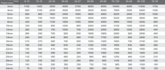
The process involves sequential removal of a layer of metal in a circle of a given diameter using a cutting tool. Drilling metal combines two types of motion - rotational and translational. To obtain the required hole dimensions in metal workpieces, it is necessary to accurately maintain the following technological process parameters:
- cutting tool rotation speed;
- speed of horizontal or vertical movement (depending on the relative position of the workpiece and drill).
A hole in the metal is obtained with the specified parameters only if the preparatory and main operations are correctly performed, as well as the selection of the necessary equipment and cutting tools. Pre-drilling is often performed to obtain the required accuracy. It's called draft. The operation is performed with a reduced accuracy class. Next, the finishing operation is carried out using high-precision machines and tools for metal workpieces.
The process itself is carried out in various modes: using hand tools (drill or other tools), special drilling or metal-cutting machines.
In all cases, different types of drills are used to obtain the required hole. On drilling machines, a chuck with a fixed drill rotates and is brought to the surface of the workpiece. On metal-cutting machines, the drill is fixed in the tailstock of the machine, and the workpiece rotates. The second method allows you to obtain higher accuracy of the hole and the walls of the resulting hole.
Depending on the tasks, the following types of drills are used for both methods:
- spiral (the most common type of this tool);
- with soldered plates on the cutting edge;
- centering;
- cannon;
- feather (used for drilling holes in workpieces made of any type of wood).
Twist drills with their transverse edge exert pressure on the surface of the metal. This process accounts for more than 65% of the force during rotational and translational motion. At this moment, there is a significant increase in temperature of both the surface of the workpiece and the leading edge of the drill. Therefore, it is necessary to properly observe the thermal regime during the drilling process.
To speed up the cutting process in twist drills, so-called double sharpening is used. It allows you to work more efficiently on the hardest grades of metal, including cast iron. Such sharpening leads to an increase in chip width, the main angle decreases, and the durability and durability of the drill increases.
The technology for creating centering holes involves the use of special centering drills. They are made of tool steel and have a double-sided combined design.
Applying plates with increased strength to the cutting edge of the drill allows them to be used for drilling products made of cast iron, metal of increased hardness, dense building structures (concrete, stone, ceramic granite, etc.).
Feather drills differ in the design of the cutting edge. It is made in the form of plates. They are usually used to make holes in wood pieces. Sometimes special point drills are used to make holes in solid forgings and some types of castings.
Drilling, reaming, countersinking, reaming
18>
Drilling is used for processing blind and through holes of cylindrical, conical and multifaceted internal surfaces.
Two types of drilling are used:
— actual drilling (obtaining holes with a diameter of up to 12 mm in solid material);
— drilling (increasing the diameter of a previously drilled, cast, stamped, stitched hole, obtained by electrophysical or electrochemical processing methods).
Drilling and reaming ensure the accuracy of machining holes according to the 10-11th quality and surface quality Rz 80...20 µm (when machining small-diameter holes in non-ferrous metals and alloys up to Ra 2.5 µm). To obtain more accurate holes, countersinking and reaming are used.
Countersinking, like drilling, is used to increase the diameter of a previously obtained cylindrical hole, as well as to obtain conical (conical countersinks) and flat (ends of countersinks) surfaces. When countersinking after drilling, accuracy of 9-10 grades is obtained, surface quality up to Ra 2.5 microns.
Reaming is used for final (finishing) processing of mainly cylindrical holes, less often for finishing of conical and end surfaces. Accuracy of 6-8 grades. Surface quality Ra 2.5 ... 0.32 microns.
Axial tools
The holes are processed with various cutting tools: drills, countersinks, countersinks, reamers, taps. All these tools are axial.
Machining with these tools is carried out with the main rotational movement of the tool or workpiece and with one feed movement (usually the tool) along the axis of the tool or the surface being processed.
Drill
Designed for drilling and reaming holes with a diameter of up to 80 mm. The following types of drills are distinguished: cylindrical with a helical flute and a conical shank (standard and extended); drills for drilling cast iron with a carbide plate; feathers for deep holes; hollow for circular drilling of holes with a diameter of more than 60 mm.
countersinks
Designed for finishing drilled holes of 11, 12-13 grades or for processing flat-bottomed sockets for screw and bolt heads. Countersinks are of the following types: with a spiral tooth, conical and cylindrical shank (high-speed or with carbide plates); with a spiral tooth (attached and solid); mounted, with insert knives, high-speed; mounted, equipped with hard alloy; for cylindrical recesses (solid and removable); for cleaning end surfaces (plate or with insert knives); countersinks with a pin lock, equipped with hard alloy plates; special for boring bars.
Sweeps
designed for finishing of holes in order to obtain the correct shape and exact dimensions in grades 6-7 and 8-9 and surface roughness in grades 7-8. The types of reamers are as follows: solid with a cylindrical or conical shank; mounted for through and blind holes; conical; special for mandrels and boring bars.
Taps
used for cutting threads in holes. A tap is a screw with cut straight or helical grooves that form cutting edges. The thread profile must match the profile of the thread being cut.
There are different types of drills: feather, spiral, gun, ring and combined special. Drills are made from high-speed, alloy and carbon steels, and they are also equipped with inserts made of hard alloys. Twist drills are the most widely used in industry. Twist drills are manufactured with a diameter from 0.1 to 80 mm.
A twist drill consists of a working part, a neck, a shank for fastening the drill in the machine spindle and a foot that serves as a stop when knocking the drill out of the spindle socket. The working part is divided into cutting and guiding. The cutting part consists of two teeth (feathers), formed by two grooves for removing chips; jumpers (core) - the middle part of the drill connecting both teeth (feathers); Two front surfaces along which chips run, and two rear surfaces; two ribbons to guide the drill and reduce its friction against the walls of the hole; two main cutting edges formed by the intersection of the front and rear surfaces and performing the main cutting work; transverse edge (bridge) formed by the intersection of both rear surfaces. On the outer surface of the drill, between the edge of the ribbon and the groove, there is a slightly recessed part running along a helical line - the back of the tooth.
Figure 6.1 Structural elements Figure 6.2 Drill operation
twist drill 1 - drill, 2 - chips, 3 - part.
The geometric parameters of the cutting part of the drill include: the angle at the tip of the drill, the angle of inclination of the helical groove, the front and back angles, the inclination angle of the transverse edge (jumper).
Figure 6.3 Twist Drill Geometry
Drill tip angle 2φ
located between the main cutting edges. It has a great influence on the operation of the drill. The value of this angle is selected depending on the hardness of the material being processed (from 80 to 140°): for steels, cast irons and hard bronzes 2φ = 116 - 118°; for brass and soft bronze 2φ = 130°; for light alloys, silumin, electron and babbitt 2φ = 140°; for red copper 2φ = 125°; for ebonite and celluloid 2φ = 80 - 90°.
To increase the durability of drills with a diameter of 12 mm or more, double sharpening of drills is used; in this case, the main cutting edges are not shaped like a straight line, as with conventional sharpening, but rather a broken line. The main angle is 2φ = 116 - 118° (for steels and cast irons), and the second angle is 2φ = 70 -75°.
Tilt angle
The helical groove is designated by the Greek letter omega (ω). As this angle increases, the cutting process proceeds more easily and chip yield improves. The value of ω depends on the diameter of the drill. For drills with a diameter of 0.25 - 9.9 mm ω = 18-28°, for drills with a diameter of 10 mm or more ω = 30°.
If we cut a twist drill with a plane perpendicular to the main cutting edge, we will see the rake angle γ
(gamma). The rake angle γ at different points of the cutting edge has different values: it is larger at the periphery of the drill and noticeably smaller at its axis. So, if at the outer diameter the rake angle is γ = 25 - 30°, then at the jumper it is close to 0°. The inconstancy of the rake angle is one of the disadvantages of a twist drill and is one of the reasons for its uneven and rapid wear.
Back angle
α (alpha) drill is designed to reduce friction of the flank surface on the cutting surface. This angle is considered in a plane parallel to the axis of the drill. The value of the clearance angle also changes in the direction from the periphery to the center of the drill: at the periphery it is 8 - 12°, and at the axis α = 20 - 26°.
Cross edge angle
(psi) for drills with a diameter of 1-12 mm from 47 to 50°, and for drills with a diameter of more than 12 mm = 55°.
A countersink is used to process holes that are pre-stamped, cast or drilled. The allowance for countersinking (after drilling) is 0.5-3 mm per side. The countersink is selected depending on the material being processed, the type (through, stepped, blind) and diameter of the hole and the specified processing accuracy. A countersink has three or more cutting edges, so when countersinking, thinner chips are removed and more accurate holes are obtained than when drilling; it is stronger than a drill, due to which the feed rate for countersinking is 2.5-3 times higher than the feed rate for drilling. Countersinking can be either a preliminary (before deployment) or a final operation. In addition to processing holes, countersinks are used for processing end surfaces. To increase the accuracy of countersinking (especially when processing cast or stamped deep holes), it is recommended to first bore (with a cutter) the hole to a diameter equal to the diameter of the countersink to a depth approximately equal to half the length of the working part of the countersink. For processing high-strength materials (sв>750 MPa), countersinks equipped with hard alloy plates are used. The cutting speed for high-speed steel countersinks is the same as for drills. The cutting speed of carbide countersinks is 2-3 times higher than that of high-speed steel countersinks. When processing high-strength materials and crust casting, the cutting speed of carbide countersinks should be reduced by 20-30%.
Figure 6.4 Countersinking holes
A countersink has more cutting edges (three or four) than a twist drill and provides a cleaner hole.
Countersinking is the processing of the exit part of a hole (deburring) to obtain conical or cylindrical recesses for the countersunk heads of rivets and screws. Countersinking is performed with a conical or cylindrical countersink. Countersinking operations are performed on a drilling machine, as is drilling holes to the required depth.
Figure 6.5 a - countersink, b, c conical Figure 6. 6 Countersink operation:
and cylindrical countersinks 1-piece, 2-countersink
Main angle
in terms of cutting edges, in most cases it is equal to φ = 60°. For high-speed countersinks working on steel and all carbide countersinks, it is recommended to create a transition edge with an angle φi = 30° and a length of 0.3-1 mm.
The geometric parameters of the cutting part are usually specified in a section by a plane perpendicular to the projection of the cutting edge onto the axial plane of the countersink. Front corner
selected depending on the properties of the material being processed: for steel 8-12°, cast iron 6-10°, light and non-ferrous metals 25-30°. The rear angle is taken to be 8-10°.
For proper operation of the countersink, it is necessary that the runout of the main edges does not exceed 0.05-0.06 mm.
Tilt angle
grooves to the tool axis are taken within the limits ω = 10-20°. Countersinks with a diameter of 10-32 mm are made with tail ones, and with a diameter of 25-80 mm - with attachment ones.
The use of countersinks equipped with carbide plates can significantly increase processing productivity. Carbide plates can be soldered directly into the countersink body or onto an insert knife. The use of prefabricated structures makes it possible to replace teeth if they break, restore and adjust the size of the countersink, and reuse the housing. To avoid chipping of the hard alloy, a negative chamfer (γ = -10°; f = 0.2-0.3 mm) is often introduced on the front surface of the hard alloy.
The rear surface of the cutting and calibrating part of the countersink, equipped with a hard alloy, is made at two angles.
To obtain holes of high accuracy and quality of the machined surface, reaming is used. A reamer has significantly more cutting edges than a countersink, so reaming removes thinner chips and produces more accurate holes than countersinking. Holes with a diameter of up to 10 mm are deployed immediately after drilling. Before deploying holes of larger diameter, they are pre-processed and the end is trimmed. Reaming allowance t=0.15-0.5 mm for rough reamers and 0.05-0.25 mm for finishing reamers. When working with finishing reamers on lathes and turret lathes, swinging mandrels are used, which compensate for the misalignment of the hole axis with the reamer axis. In order to ensure high quality processing, drilling, countersinking (or boring) and reaming of the hole are carried out in one installation of the workpiece in the machine chuck. Feed when unrolling steel parts is 0.5-2 mm/rev, and when unrolling cast iron parts 1-4 mm/r. Cutting speed during reaming 6-16 m/min. The larger the diameter of the hole being machined, the lower the cutting speed at the same feed, and as the feed increases, the cutting speed is reduced.
Reamers are cylindrical and conical. Taper reamers are designed for reaming tapered holes.
Figure 6.7 Reamers: cylindrical manual,
cylindrical machine, conical
On the working part of the reamer there are from 6 to 14 cut teeth, along which grooves are located; The teeth serve to form cutting edges and remove the removed chips outward. The lower conical part of the reamer removes chips, and the upper - calibrating - guides the reamer and finally calibrates the holes.
For cleaner surface treatment of holes and cooling of the tool during reaming, drilled holes in steel are lubricated with mineral oil, in copper with emulsion, in aluminum with turpentine, and in brass and bronze holes are reamed without lubrication.
Reamers can be manual or machine, tail or mounted, solid or prefabricated, made of steel (alloyed or high-speed) or with carbide plates.
Manual reamers used in metalworking work are distinguished by a small angle φ = 1-2 and a long cutting part. These reamers are usually made from 9ХС steel.
Machine reamers are used when working on lathes, turrets and drilling machines. The leading angle at the cutting part is φ = 15° for ductile metals and φ = 5° for brittle metals. At the front end of the cutting part, the lead-in chamfer is removed at an angle of 45° to guide the reaming in the hole, protect the teeth from chipping when entering the hole and remove excessive allowance.
The calibrating part of the reamer is used to calibrate and clean the hole and the direction of the reamer during processing. The teeth on the calibrating part have a cylindrical ribbon that requires very careful finishing.
To prevent cutting of the holes, the teeth of the reamer are unevenly spaced, so sharpening the reamer in the indexing devices is impossible.
The rake angle γ for reamers is usually zero and only for rough reamers or when processing particularly tough materials is γ = 5-10°. The clearance angle on the cutting part is a = 8°. Reamers equipped with carbide are sharpened along the back surface at two back angles α1 = 8° and α2 = 15°.
Taps are a tool used for cutting internal threads.
Hand taps are used to cut threads by hand; used as a set. There are sets of two pieces (roughing and finishing taps) and three pieces (roughing, intermediate and finishing taps).
Nut taps (short, long and machine) are used for cutting through threads.
Machine taps are used on drilling and aggregate machines, on automatic machines, and for cutting threads in machine parts.
Adjustable (assembled) taps are used for cutting large diameter threads.
Tap elements. The tap consists of the following parts: working part and shank; the working part is divided into an intake part and a calibration part; the shank ends with a square that transmits torque to the tap. The grooves of the tap serve to form the front and rear surfaces of the cutting feathers and to remove chips.
The tapping part of the tap cuts off the allowance on the workpiece, and the calibrating part is designed to center and guide the tap in the hole being cut and for cleaning the thread being cut. The tap has front, back and profile surfaces and main and profile cutting blades.
Figure 6.8 Tap.
The geometric parameters of the tap include: rake angle γ, which is taken from 0º to 5º when processing cast iron and bronze, and for mild steel γ reaches 15º; rear angle α, which ranges from 6 to 12º; the angle of the intake part φ, determined by calculation, it depends on the height of the thread being cut and the selected length of the intake part; reverse cone angle φ, necessary to prevent pinching of the tap in the thread being cut; the reduction in diameter is given by 0.05 ÷ 0.1 mm per 100 mm of tap length; the angle of inclination of the cutting blade λ is sharpened along the length of the cutting part of the tap to direct the chips forward along the movement of the tool; the value of λ is taken in the range from 7 to 10º.
18>
Date added: 2017-01-26; views: 12973; ORDER A WORK WRITING
Find out more:
Drilling, countersinking, reaming
Drilling is one of the most common methods of producing holes through cutting. The cutting tool is a drill.
Drilling is performed on drilling machines and manually - with hand drills and power tools - with electric and pneumatic drilling machines. In recent years, drilling of holes has also been carried out using electric spark and ultrasonic methods on special machines.
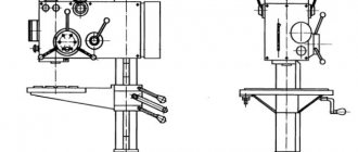
At shipbuilding plants, the most common vertical drilling machines are grade 2118 (maximum diameter of drilled holes 18 mm); 2A125 (hole up to 25 mm); 2A135, etc. Radial drilling machines of brands 2A53, 2A55, etc. are also used.
When drilling, the workpiece is secured on the drilling machine table with clamps, in a vice or otherwise. The drill is exposed to two joint movements - rotational, called the main (working) movement, and translational (directed along the axis of the drill), called the feed movement.
Twist drills are used to drill holes. Such a drill (Fig. 4.13) consists of two main parts: the working part and the shank, with which the drill is secured in the machine spindle. Shanks are either conical or cylindrical. A drill with a cylindrical shank is fixed in special chucks.
Rice. 4.13. Elements of a twist drill. 1 - front surface: 2 - back of the tooth; 3 - rear surface; 4 - transverse edge; 5 - tooth; 6 - groove; 7 — cutting edge; 8 — ribbon; 9 - core; 10 — apex angle; 11 — jumper blade; 12 - recessed inclination of the transverse edge.
The working part of the drill consists of a cylindrical and cutting part. The cylindrical part has two helical grooves of a special profile, which ensures the correct formation of cutting edges and sufficient space for the passage of chips. Two narrow strips located along the helical grooves and called ribbons serve to reduce friction of the drill against the walls of the hole, guide the drill into the hole and prevent the drill from moving to the side. To reduce friction, the reverse cone of the working part of the drill is also used, since the diameter of the drill at the cutting part is larger than the diameter at the shank (cone 0.03-0.1 mm per 100 mm of length).
The angle at the tip of the drill (between the cutting edges) is of great importance, since the correct operation of the drill and its productivity depend on it. For steel it is 116-118°, for aluminum-magnesium alloys - 115-120°.
The durability of a drill (the time between two regrinds) is influenced by the properties of the material being processed, the drill material, sharpening angles and the shape of the cutting edges, cutting speed, chip cross-section (feed rate) and cooling.
During the cutting process, drilling generates a large amount of heat, which can lead to tempering, i.e., a decrease in the hardness of the cutting part. Therefore, to increase the durability of the drill, special cutting fluids (soap and soda water, oil emulsions, etc.) are used. They not only cool the drill, the part and the chips, but also significantly reduce friction, thereby facilitating the cutting process.
For drilling some materials (hard steel, cast iron, glass, etc.), drills with plates made of hard alloys are used, which can dramatically increase labor productivity.
A dull drill makes a characteristic creaking sound during operation. Such a drill must be sent for regrinding. Sharpening of drills should be carried out by specialist sharpeners in tool stores or workshops.
To fasten drills in the spindle of a drilling machine, auxiliary tools are used, which include: adapter bushings, drill chucks of various types, mandrels, etc.
When securing parts to the machine table, various clamping devices with screw clamps are widely used.
Recently, devices with manual quick-release clamps - eccentric, wedge and others, as well as with mechanized pneumatic and hydraulic clamps have become widespread. When drilling holes in them with a diameter of up to 10 mm, small parts are secured in a hand vice or on a universal prismatic support.
Drilling along the markings with center punching is carried out in two steps: first, a hole is pre-drilled with a manual feed of 0.25 of the hole diameter, then the drill is raised, the chips are removed and the coincidence of the hole with the marking circle is checked. If they match, then continue drilling by turning on the mechanical feed. If the overdrilled hole is not in the center, then it is corrected by cutting two or three grooves from the center on the side of the recess where the drill needs to be moved. The grooves guide the drill to the location designated by the center punch. Then continue drilling as indicated above.
In cases where high drilling accuracy is required, as well as with a sufficiently large batch of parts, holes are drilled without marking using special jigs.
When drilling blind holes to a given depth, the machine is pre-set using a special device. If there is no such device, then a thrust sleeve is put on the drill and secured with a locking screw at a given height.
When drilling through holes, when the drill approaches the exit of the hole, it is necessary to reduce the feed, since the drill can grab a large layer of metal, jam and break.
Countersinking is the processing of the inlet or outlet part of a hole in order to remove chamfers, burrs, and also form recesses for the heads of bolts, screws and rivets. For this purpose, conical and cylindrical (according to the shape of the cutting part) countersinks are used. Countersinking is performed on drilling machines and using electric or pneumatic machines. Fastening countersinks is similar to fastening drills.
Reaming is a hole finishing operation that provides high dimensional accuracy and surface finish.
This operation is performed using a tool called a reamer. Reaming of holes is carried out on drilling machines using special machine reamers (with a short cutting part) and manually. In manual reamer, the tool is rotated using a crank that fits onto the square end of the reamer shank. Holes for the reamer are drilled with a diameter allowance of no more than 0.2-0.3 mm for a rough reamer and no more than 0.05-0.1 mm for a finishing reamer. The reamer is pre-lubricated and inserted into the hole so that its axis coincides with the axis of the hole.
Abstract "Drilling of metals"
Devices for securing workpieces are placed on the work table.
The body contains all the main parts of the machine; the column is attached to the table and body. The electric motor drives the spindle through a belt drive. A chuck with a drill is attached to the spindle. Lifting mechanism
moves the machine body up or down the column. The feed mechanism moves the spindle with the chuck down while drilling. The “start” and “stop” buttons turn the electric motor on and off.
1.3. Tools for drilling holes.
The main tool when drilling holes is a drill. There are various drills, but the most commonly used are twist drills.
Twist drill device.
Chapter 2. Drilling techniques.
Before drilling, you need to mark the center of the hole by punching it. To do this, you need to place the tip of the center punch at the expected center of the hole and hit it with a hammer. Punching is necessary to prevent the drill from slipping at the first moment of drilling. If the punch mark is not large enough to hold a large-diameter drill, then you should widen the hole with a small-diameter drill. Low and medium speeds are optimal for drilling most metals - 500-1000 rpm. High speeds quickly heat up the drill, which can result in annealing and softening. When drilling, do not press too hard on the drill; the feed should be slow and smooth.
To create better drilling conditions, it is advisable to dip the tip of the drill in machine oil or drop it into the core site. Oil in the drilling area helps to better cool the drill and makes cutting metal easier. A drill used for drilling using oil becomes less dull, requires less sharpening and lasts longer. A special emulsion, soapy water, and kerosene are also used as a coolant.
When through drilling with high feed, a burr (burr) is formed at the exit of the hole, to which the drill clings with the cutting edges. As a result, a sudden blockage of the drill and its fracture may occur. To avoid burr formation, you need to finish drilling holes in the metal with low feed. It is also advisable to place a wooden block under the part being drilled, which prevents the formation of a burr. The block and the workpiece must be pressed tightly against each other. Most often it is necessary to drill steel, but often it is necessary to drill other metals that have their own drilling characteristics. Aluminum, for example, envelops the drill, making it difficult for it to penetrate deeper and widening the resulting hole. If you need to drill a precise hole in aluminum (for example, for a thread), you must use coolant and remove the drill from the hole more often to clean it. Large diameter holes should be drilled in stages. First you need to drill the part with a thin drill, then drill the hole to a larger diameter. For example, it is better to drill a hole with a diameter of 12 mm in two or three steps - sequentially with drills of 5, 10 and 12 mm.