Reaming holes
Reaming is used for finishing of holes of 7-9 grades and roughness Ra = 2.5-0.5 µm after drilling (only up to a diameter of 10 mm), zekering or boring.
Reaming is the most productive and common method for finishing holes up to 100 mm in diameter.
Turning sequentially with two reamers can provide class 10 surface roughness. Reaming cannot eliminate runout or misalignment of the hole if it remains after previous processing.
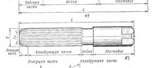
The cutting tools for the considered processing method on lathes are machine reamers (Fig. 66). They differ from countersinks in a large number of teeth (usually from 6 to 14), which cut off small chips, thereby increasing the accuracy of processing.
According to the method of installation on the machine, reamers are divided into tail-mounted and mounted, and according to the design of the working part - into solid and prefabricated.
The latter consist of a body and knives fixed in its grooves.
The tail reamer (Fig. 66, a) consists of a shank, a neck and a working part. In turn, the working part is divided into cutting, calibrating and return cone.
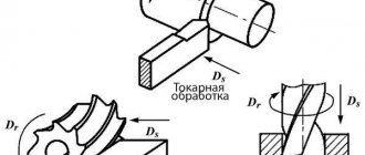
The main cutting edges are located on the cutting part. Their inclination to the axis is determined by the plan angle φ, the value of which depends on the purpose of the alignment. For through holes when processing steels and other ductile metals φ=15°, for brittle metals φ=5°. Reamers for blind holes have φ = 60°.
The calibrating part has a cylindrical shape. There are auxiliary cutting edges on it, intended for cleaning and calibrating the hole. To prevent the ends of the teeth of the calibrating part from damaging the holes, a slight reverse cone is made on a small section of it.
Due to the different purposes of the main and auxiliary cutting edges, the shape of the sharpening of the teeth along the length is different. On the cutting part (section A-A), the teeth are sharpened to sharpness; on the calibrating (section B-B) narrow cylindrical ribbons are left along the rear surfaces of the teeth, which smooth the surface of the hole, improve the direction of reaming and increase the number of regrinds.
The front angle γ for reamers is usually 0°. With increased requirements for the quality of processing, it is recommended to make it negative to -5°. As a result, cutting during deployment resembles scraping.
The load on the teeth of the reamers always fluctuates during the cutting process, which is caused by the uneven density of the material being processed and various inclusions in it. Periodically repeating vibrations with uniformly spaced teeth create local depressions on the surface of the reamed hole. The uneven arrangement of the teeth of the reamers around the circumference eliminates this phenomenon and helps to improve the cleanliness of the processing.
Reamers usually have straight teeth. In some cases, to process holes with grooves or grooves, reamers with helical teeth are used, the direction of which is made opposite to the cutting direction so that the reamer is not pulled into the hole.
General purpose reamers are produced with a diameter from 0.1 to 300 mm in finished form for holes of 7-9 grades (H7, H8, H9, K7) or with an allowance for finishing. The latter are produced in six numbers. They can be used for machining holes of the intended accuracy only after finishing the calibrating part.
The working part of the reamers is made of high-speed steel or equipped with a hard alloy to increase durability.
Reamers are marked with nominal diameter, accuracy and material.