Purpose, design elements and geometric parameters of a twist drill
Purpose, design elements and geometric parameters of a twist drill
Drills are designed for making holes in solid material, for drilling existing holes to a larger size, as well as for drilling conical recesses in solid material. Drilling provides 12 ..11 quality accuracy and roughness of the machined surface with Ra=80...20 microns.
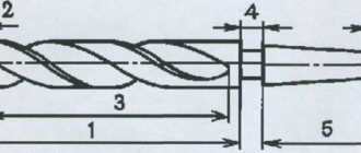
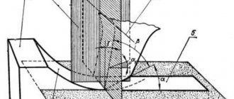
The most widely used in industry are spiral drills made of high-speed steel with a cylindrical shank (diameters from 0.1 to 20 mm) and a conical shank (diameters from 6 to 80 mm). The main dimensions of drills, such as drill , length of the working part, shank dimensions, as well as accuracy parameters, are standardized. A twist drill consists of a working part l1 (Fig. 1.22), a neck l3, a shank l4 with a foot l5 at the end. The cutting part is directly performed by the cutting part /„. The remaining section l2 of the working part serves to remove chips, guide the drill in operation, and serve as a reserve for regrinding the drill. Therefore, part l2 is called the guiding part, sometimes it is called the calibrating part.
Shank l4 is used to secure the drill directly in the conical socket of the machine spindle or in the socket of the adapter sleeve. Cylindrical shanks are fixed in special collet or three-jaw self-centering chucks. The cutting torque is transmitted by frictional forces arising on the surfaces of the shank. Foot l5 is intended for knocking out the drill from the slot of the machine spindle or adapter sleeve, and neck l3 is for exiting the grinding wheel when grinding the shank and the working part.
The working part of the drill consists of two feathers (teeth) 4, two helical grooves 2 and a core 1, the diameter of which dc towards the shank increases slightly to increase the strength and rigidity of the drill . Each drill blade is a cutting wedge and has a front surface 9, a rear main surface 8 and a rear auxiliary surface 5, which is part of the outer cylindrical surface of the drill remaining after the formation of the back 7, and is called a cylindrical strip. The back of the pen 7 also has a cylindrical shape, but its diameter is smaller than the diameter of the drill D. Lowering the back is necessary to reduce friction when the drill cylindrically by the surface D of the already machined part of the hole. As a result, the role of a guide surface is played by a narrow circular ground strip 5.
In accordance with the working surfaces of the drill , there are two main cutting edges 3, two auxiliary cutting edges 10 and a transverse cutting edge b at the junction of two rear surfaces 8.
In a static coordinate system, the main plane is the axial plane of the drill , passing through the point of the main cutting edge under consideration, since it is perpendicular to the cutting speed vector at this point. The cutting plane is the plane perpendicular to the main one and passing through the main cutting edge. Therefore, the sharpening angles of the drill are considered and determined in the same way as for the cutter, which is laid out in a dotted line on the drill with the working surfaces, main and auxiliary cutting edges aligned (Fig. 1.23).
Like a cutter, each drill blade has a main φ and an auxiliary φ1 angle in the plan, an inclination angle of the main cutting edge λ, but measured in projection onto a plane perpendicular to the axis of the drill , a front angle y and a rear angle in the normal secant plane. Twice the lead angle, 2φ, is called the drill .
Features of the design and operating conditions of the drill introduce some differences into the geometry of its cutting part compared to the cutter. Due to the presence of a transverse edge, the angle ψ of the position of this edge additionally appears, depending on the values of the rear angles αN a as well as the rear αp and strongly negative front γp angles of the transverse cutting edge (see Fig. 1.23). The rear auxiliary angle is zero, since the rear auxiliary surface is part of a cylinder with diameter D. The angle φ1, intended to reduce friction on the machined surface, is very small (1-2') and is formed due to the reverse taper of the working part, i.e. due to a slight reduction in the diameter of the drill towards the shank. The main relief angle a is specified in the O-O plane (see Fig. 1.23), parallel to the axis and perpendicular to the main plane. For a cutter, it is the transverse clearance angle. The transverse rake angle of the cutter is the angle of inclination with the helical flute of the drill .
The rake and back angles are not constant along the main cutting edge; from the periphery to the center of the drill, the rake angle decreases and the back angle increases. The specified nature of the change in the rear angle is ensured by the form of sharpening of the rear surfaces, and the front angle is determined by the method of manufacturing the helical flute of the drill . With a constant groove pitch, its inclination angle c, which is the longitudinal rake angle of the drill , decreases as it approaches the center of the drill. During operation, the intensity of change in working angles is somewhat less than static ones, since αPx = αx - μx (see Fig. 1.23), γPx = γx+μx, and μx=arctg(S7/πDx) increases as the drill axis approaches ( see Fig. 1.23). But nevertheless, the kinematic, or working, angles of the drill are not constant along the cutting edge, and therefore are not optimal, which is a big disadvantage of the drill .
The nature of the change in the static rake angle is determined by the formula.
Recalculation of the rear angle from one cutting plane to another is carried out using the formula:
see also
- Cutting tool. Definition, purpose, requirements, optimality criterion
- Geometric parameters of the cutting wedge
- Materials for the manufacture of cutting tools
- Purpose and types of cutters
- Turning cutters
- Prefabricated cutters
- Holder cutters
- Semi-automatic and automatic turret cutters
- Shaped cutters
- Planing and slotting tools
- Purpose, design elements and geometric parameters of a twist drill
- Design features of drills for various purposes
- Purpose, structural elements and geometric parameters of countersinks and reamers
- Purpose and types of cutters
- Design elements and geometric parameters of cutters
- Purpose and main types of broaches
- Structural elements and geometric parameters of broaches
- Methods of thread formation and threading tools
- Thread rolling tools
- Methods for cutting gear products
- Gear cutting tools using the copying method
- Gear cutting tools using the rolling method
- Bevel Spur Gear Cutting Tools
- Worm Wheel Machining Tools
- Definition, purpose, effectiveness and scope
- Purpose and form of abrasive tools
- Components and characteristics of abrasive tools
- Cutting tools
- Auxiliary tools