Lathe chucks. Varieties, features of selection and operation
Lathe chucks - also called clamping devices, are intended for installation on the front end of the spindle of lathes. The design of the lathe chuck provides high clamping force on the workpiece, ensures centering accuracy and perpendicularity of the surfaces of the processing axis.
Domestic and foreign manufacturers make chucks for lathes from durable cast iron or based on a hardened steel body; they include a set of hardened jaws.
- Content
- Enterprises producing lathe chucks
- State standards regulating the design and dimensions of lathe chucks
- Types and classification of lathe chucks
- Self-centering three-jaw chucks GOST 2675-80
- Lathe chuck designation system
- Marking of lathe chucks produced by BelTAPAZ
- Marking of Polish lathe chucks Bison-Bial type “ST”
- Spiral cartridges
- Intermediate (transition) flanges for lathe chucks
Enterprises producing lathe chucks
- Grodno Lathe Chuck Plant - Currently - BelTAPAZ produces lathe chucks and is the largest manufacturer in the CIS;
- Baranovichi machine tool accessories plant BZSP - The plant produces manual steel lathe chucks, steel lathe chucks with mechanized clamping, 2-, 3-, 4-jaw;
- Inrost, LLC Ekaterinburg - The company produces manual 3-jaw lathe chucks;
- The Pskov technological equipment plant produces self-centering lathe chucks with manual drive;
- Orsha Tool Plant OIZ - The plant produces three-jaw drill chucks, thread-cutting chucks and machine tooling;
- Novosibirsk Tool Plant - The plant produces three-jaw drill chucks.
Enterprises producing lathe chucks in the USSR
- Pskov Machine-Building Plant Pskovmash - manufactured self-centering lathe chucks with manual drive;
- Paveletsky plant of machine components PZSU - The plant ceased to exist. The plant was the only manufacturer in Russia of 4-jaw lathe chucks with independent movement of the jaws;
- Borisoglebsk Lathe Chuck Plant - Production of lathe chucks has been discontinued. The plant produced three-jaw self-centering and four-jaw chucks with independent movement of the jaws.
- Lugansk Machine Tool Plant - Currently - Lugansk Cartridge Plant - the plant does not produce lathe chucks. Produced lathe chucks with a diameter of 125 mm (7100-0003), 250 mm (7100-0009) with a faceplate fit
- Frunzensky Machine-Building Plant named after. Lenin - Currently - Bishkek Machine-Building Plant . The most famous products: lathe chucks with a diameter of 160 mm (7100-0005), 250 mm (7100-0009)
Foreign suppliers of lathe chucks to Russia
- BISON-BIAL Poland - Official representative of the plant in Russia - Skalt LLC St. Petersburg
- Jet, China - Lathe chucks for Jet machines
- Proma, China – Lathe chucks for Proma machines
State standards regulating the design and dimensions of lathe chucks
- GOST 1654 - General purpose lathe chucks. General technical conditions
- GOST 2571 - Drive lathe chucks. (for spindles according to GOST 12593-72 and GOST 12595-85)
- GOST 2675 — Self-centering three-jaw lathe chucks. Main Dimensions
- GOST 14903 — Self-centering two-jaw lathe chucks
- GOST 24351 — Self-centering lathe chucks 3- and 2-jaw wedge and lever-wedge
- GOST 24568 - Magnetic cartridges. Specifications
- GOST 3890 - Four-jaw chucks with independent movement of the jaws
- GOST 16157 — Membrane chucks for grinding holes in gears
State standards regulate the operational and technical parameters according to which lathe chucks for machine tools are selected:
- A number of possible outer diameters of chucks and, accordingly, a range of workpiece sizes: maximum and minimum diameter (outer and inner), depending on the method of fastening - on direct or reverse cams. The maximum permissible weight of the workpiece is taken into account;
- Method of attaching the chuck to the spindle. Connecting dimensions: diameter of the centering belt or centering cone;
- Location and dimensions of mounting holes in the lathe chuck;
- Limits of turning speed of the lathe chuck;
- The diameter of the hole in the chuck body for installing a rod or pipe;
- Lathe chuck accuracy
Specifications
The body of the cartridge device is made of high-quality cast iron of special manufacture.
Technical characteristics of a standard three-jaw self-centering chuck:
- Outer diameter 250 mm;
- diameter of the connecting belt 200 mm;
- diameter of the hole in the body is 76 mm;
- the mounting holes have a diameter of 224 mm;
- the largest outer diameter of the product clamped in direct and reverse jaws is 120 and 266 mm, respectively;
- The highest permissible rotation speed is 2000 rpm;
- The weight of the device is 29 kg;
- The cartridge element is secured with 6 M12 bolts.
//www.youtube.com/embed/34nSzLpLGak
Using direct and reverse cams, it can be used to fix installations of various sizes and diameters. A straight cam is used to secure the workpiece to the outer surface for a shaft or the inner surface of a hole in the workpiece.
Types and classification of lathe chucks
Number of jaws in the chuck and their design
Lathe chucks are distinguished by the number of jaws: 2; 3; 4; 6
- 2-jaw self-centering chuck - used for clamping small asymmetrical workpieces (rebar, cast parts, forgings). Cartridges of this type have a fairly simple structure. Both manual and mechanized (pneumatic) chucks are used;
- 3-jaw self-centering chuck - usually used for fastening round and hexagonal workpieces, it is most widespread. The reason for its high popularity is the speed of centering and clamping of parts, which is especially important in small-scale production, where workpieces are changed very often;
- 4-jaw chuck with independent installation of jaws - used for fastening rectangular and asymmetrical parts, as well as square bars. The chuck has cams that move independently of each other, which provides it with wide capabilities;
- 6-jaw self-centering chuck - allows you to process thin-walled parts without deforming them. The gripping forces in a six-jaw lathe chuck are distributed evenly across the 6 jaws.
Cams are divided into direct and reverse:
- Straight jaws - clamp the part from above, along the outer surface;
- Reverse cams - clamp the part from the inside, the part must have a corresponding hole, be hollow, for example a pipe;
Chuck jaws of all types are manufactured in the following designs (GOST-2675-80):
- Solid cams - made from a single piece of steel with a tensile strength σB of at least 500 MPa and heat treatment of the clamping and rubbing working surfaces to a hardness of at least 43 HRCE;
- Prefabricated cams - consists of a rail (base) made of hardened steel, onto which an overhead cam, which can be made of non-hardened steel or non-ferrous metal, is attached with screws.
- Overhead jaws - used for fastening workpieces of large diameters;
Cartridge accuracy class
The cartridge accuracy class has five levels (GOST 1654-86):
- N - cartridge of normal accuracy;
- P - high-precision cartridge;
- B - high precision cartridge;
- A is a particularly high precision cartridge.
Material of body and parts of lathe chucks
Lathe chuck bodies (GOST 1654-86) must be made of the following materials:
- made of cast iron in terms of quality indicators no lower than those of the SCh 30 brand;
- made of steel with a tensile strength σB of at least 500 MPa and heat treatment of working surfaces to a hardness of at least 43 HRCE
Parts of lathe chucks must be made of steel with a tensile strength σB of at least 500 MPa and heat treatment of the working surfaces to a hardness of at least 57 HRCE;
A steel body is more expensive to produce than a cast iron one , but it allows you to significantly increase the number of revolutions of the cartridge.
Lathe chucks with wet jaws
To ensure accurate centering and perpendicularity of surfaces, so-called raw jaws are usually used, which are bored exactly along the diameter of the part to be fixed. These jaws include assembled jaws for a lathe chuck. The cams consist of a heat-treated base (rack) into which a threaded cylindrical pin is pressed. 2 cylindrical, hexagonal, rectangular or other shapes are attached to the base of the cam using screws 3.
In “raw” cams, it is possible to fasten parts on the outer final processed surface of which no traces of cam clamping are allowed, as well as to process thin-walled bushings. In the latter case, it is necessary to bore the cams so that they cover 90-95% of the surface of the workpiece.
"Raw" jaws are very effective at securing the threaded part of the part into the chuck. In this case, the corresponding thread is cut in the cams and the part to be processed is screwed into this thread, and then additionally clamped with the cams.
Type of drive used in the chuck
The chuck can have a manual drive or a mechanized drive .
- Manual drive - the part is clamped in the chuck by a person, usually using a key;
- Mechanized drive - automates the process of clamping and releasing the workpiece with a given force.
- Pneumatic drive - used mainly on automatic lathes
- Hydraulic drive - hydraulic chucks are more often used on machines with a chuck diameter greater than 200 mm.
- Electromechanical drive
If the part in the chuck is clamped manually, then this is a manually driven chuck and it is used in universal machines in conditions of individual and small-scale production.
Power-driven chucks provide good machine performance (high clamping and releasing speeds) and are used in mass production conditions.
Design of the clamping mechanism of lathe chucks
Lathe chucks have different jaw clamping mechanisms:
- The lead cartridge is the simplest type of cartridge. Designed for processing parts in centers
- The spiral self-centering jaw chuck is the most common type of design - usually 2, 3, 6 jaw chucks. The central part of the cartridge is a spiral disk. Centering occurs simultaneously with fastening;
- Independent jaw chuck - usually 4 jaw chucks. Convenient for fastening workpieces with a non-cylindrical shape, or when the axis of the cylindrical surface that is being processed does not coincide with the fastening axis;
- Lever chuck - fastening of the workpiece in a lever lathe chuck comes from a hydraulic drive, which moves the rod with the coupling. Lever chucks can be used in small-scale production;
- Wedge rack chuck - the workpiece is secured using a pneumatic or hydraulic drive. Wedge chucks demonstrate higher accuracy of workpiece centering than lever chucks;
- Collet chuck - for clamping a rod workpiece of a relatively small diameter. The advantages over other clamping devices are that the radial runout of the part, which is fixed in the collet, is so insignificant that they can be safely ignored. Collets are available as feeding and clamping;
- Drill chuck - used for fixing drills and other working tools in drilling machines;
- Diaphragm chuck - The diaphragm chuck provides the highest accuracy in centering parts. Elastic membranes are attached to the cartridge flange with bolts. Such a membrane has from 3 to 8 cams with replaceable jaws. A large number of cams on the diaphragm lathe chuck facilitates centering of the product with an accuracy of 0.05 millimeters and higher;
- Thermal Chuck - Thermal chucks are used for the same purposes as collet chucks. The difference lies in the method of clamping the tool: thermal chucks use a hot fit for this;
- Hydraulic chuck - The hydraulic chuck is an alternative to the thermal chuck. The tool is clamped in the hydraulic chuck due to fluid pressure;
- Eccentric chuck - 3-jaw eccentric chucks are used in large-scale production. They have high precision and clamping force. They can be re-adjusted to clamp another part relatively simply - by rearranging the mounted cams.
Method of attaching chucks to a lathe spindle
The method of attaching the chuck to the spindle depends on the type of spindle end and its design. In total there are 4 types of spindle ends with many standard sizes and designs. (See sidebar: Varieties of Lathe Spindle Nose Ends).
Lathe chucks have three types of fastening in accordance with GOST 2675-80 and one type in accordance with GOST 26651:
- GOST 2675-80 Type 1 - Cylindrical fit. The chuck is installed on the spindle through an intermediate flange (according to GOST 3889). The cartridge is centered on the intermediate flange through a cylindrical centering collar . The intermediate flange is either screwed onto the spindle thread (Version 1 of the intermediate flange) or installed on the centering cone of the spindle flange;
- GOST 2675-80 Type 2 - Fitting on the spindle flange taper. The chuck is installed on the centering cone of the spindle flange and secured with screws through the chuck body to the end of the spindle flange (type A) (GOST 12595);
- GOST 2675-80 Type 3 - Fit on the spindle flange taper. The chuck is installed on the centering cone of the spindle flange and secured through a rotary washer (GOST 12593);
- GOST 26651 — Fitting on the spindle flange taper. The chuck is installed on the centering cone of the spindle flange and secured with a Camlock clamp.
Varieties of front ends of lathe spindles. Designs and sizes
There are two types of spindle front ends:
- Threaded end of the spindle - in order to install the chuck on the spindle, an intermediate flange is required;
- The flanged end of the spindle has a conical guide - a centering cone that ensures more accurate centering of the chuck on the spindle. The chuck can be installed directly on the flanged end of the spindle (if the chuck has a centering cone) or through an intermediate flange in accordance with GOST 3889-80 (if the chuck has a centering collar).
Today there are four state standards regulating the design and dimensions of the front ends of spindles.
- GOST 16868 - Threaded spindle ends (Instead of OST 428)
- GOST 12595 - Type A flanged spindle ends and clamping device flanges
- GOST 12593 - Flanged ends of spindles for rotary washer and flanges of clamping devices
- GOST 26651 — Camlock-type flanged spindle ends and clamping devices
- GOST 3889 - Intermediate flanges for self-centering cartridges.
Front ends of lathe spindles
General design and arrangement of a lathe chuck for a metal machine
The following kits are supplied with the cartridge:
- straight cams;
- reverse cams;
- Cam racks are supplied outside the kit.
The most common is the three-jaw chuck, consisting of:
- monolithic or composite body with three radial grooves for cams;
- cams (direct and reverse) are made of high-quality hard, hardened steel of high strength, connected to the end thread of the spiral disk;
- a spiral disk , with a large toothed wheel on its reverse side. Associated with the bevel gear gear;
- bevel gears , by rotating a key inserted into the square hole of this gear, a rotational movement is imparted to the spiral disk.
The simplicity of technological methods for basing parts has become the reason for the popularity and spread of the three-jaw chuck on machines used in production
Key
A metal rod, at one end of which a hole is drilled perpendicular to its axis with a metal lever installed in it. Exceeding the length of the lever by 35–40% relative to the height of the key is optimal.
At the lower end of the rod there is a tetrahedral tip, commensurate with the hole inside the bevel gear. Serves as a manual drive of the cams by rotating the spiral disk while securing the workpiece in the working area of the machine.
Spring
Installed on the tip of the key. Upon completion of the operation, the load from the efforts of the hand on the key is removed and the spring, straightening, removes the key from the cartridge socket. If the machine operator inadvertently does not remove the key himself, then the spring does it for him.
Sleeve
A hollow cylinder, in the upper part of which grooves are cut for half-ring crackers. Provides fixation of the bevel gear in the working body of the cartridge. The upper part of the bevel gear with a groove for half-ring crackers is installed in the inner diameter of the bushing.
Stopper
Screw stops secure the bevel gears in the lathe chuck body.
Gear
The bevel (or small) gear is inserted into the small hole in the chuck body. Its upper part is connected to the grooves of the bushing by means of half-ring crackers.
The small gear is constantly meshed with the teeth of the large gear and is designed to transmit rotational motion to the helical disk of the chuck.
Flange
Adapter flange, faceplate. Designed for a strong and precise connection of the chuck with the working end of the machine spindle. For example, a thread is cut on the TV-4 spindle, an adapter flange (faceplate for a lathe chuck) is installed on it, onto which the lathe chuck is attached.
Spiral disk
Archimedes spiral, snail, planetary. A metal disk with large gear teeth on one side that are permanently meshed with the bevel gear gear.
On the other side of this disk, a spiral profile is cut out, which is in constant contact with the grooves (racks or combs) of the cams. The latter, moving synchronously, work to clamp, center and fix the part in the processing area of the machine.
The part clamped by the cams is removed by rotating the chuck key in reverse.
Reverse cam
Used for clamping large diameter parts. Each cam has two stages for fastening parts for expansion and one prism for compression.
Cam stages are used to eliminate end runout of the part. In addition, machine operators independently create an additional fastening base on the return cams that works to expand.
Straight cam
Straight jaws are used to clamp smaller diameter parts.
Frame
Depending on the design and methods of attachment to the spindle, it can be conditionally divided into monolithic (the body is one basic part) and composite, in which the body is divided into two basic parts:
- Monolithic with a cylindrical belt . It is attached to the spindle through an intermediate flange according to special GOST. Made from high-quality steel and less often from cast iron.
- Composite body . The base part is divided into two components:
- the front part or body (sometimes the front semi-body), it contains a spiral disk and slots for the cams;
- the rear part or flange (often the rear half-body), which houses bevel gears.
Top jaws
They are mounted on the cam rails of the lathe chuck. They are made from unhardened steel grades and are called “raw cams”. Designed for fastening large diameter parts.
GOST 2675—80 Self-centering spiral-rack three-jaw chucks
GOST 2675—80 Self-centering spiral three-jaw chucks
GOST 2675—80 Self-centering spiral three-jaw chucks
The standard applies to self-centering spiral rack three-jaw lathe chucks mounted on machine spindles through adapter flanges and directly on the flanged ends of the spindles.
In total, the standard provides for ten standard sizes of lathe chucks : 80, 100, 125, 160, 200, 250, 315, 400, 500, 630 mm.
Depending on the method of installation on spindles, lathe chucks should be made of the following 3 types:
- Type 1 - with a cylindrical, belt and with fastening through an intermediate flange in accordance with GOST 3889;
- Type 2 - with mounting on the flanged ends of spindles under a rotary washer in accordance with GOST 12593;
- Type 3 - with mounting on the flanged ends of spindles in accordance with GOST 12595.
- Ten standard sizes -: 80, 100, 125, 160, 200, 250, 315, 400, 500, 630 mm;
- Version 1 - with solid cams;
- Version 2 - with assembled jaws;
- Accuracy class - N - normal; P – increased; B – high; A – especially high;
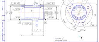
Self-centering three-jaw chuck. Type 1 - with cylindrical, belt and with fastening through an intermediate flange according to GOST 3889
GOST 2675-80 Self-centering three-jaw chuck. Type 1 - with a cylindrical belt
Self-centering three-jaw chuck. Type 3 - installation on the spindle cone, secured with screws through the chuck body into the end of the spindle flange according to GOST 12595
GOST 2675-80 Self-centering three-jaw chuck. Type 3 - installation on the spindle taper
Three-jaw drive chucks
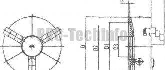
Three-jaw driving chucks are designed for fastening workpieces installed in the centers.
The front center 1 is fixedly fixed in the cartridge. Preliminary adjustment of cams 2 to a given size is carried out by rearranging them along the corrugated surface. Thanks to the articulated connection of the rod 4 with the coupling 5 , the cams can self-align, thereby achieving uniform clamping of the workpiece. The ratio of lever arms 3 is 1:2.5. Installed on the adapter flange.
Drive - pneumatic.
Dimensions in mm
| Diameter blanks | D | D1 (add. off according to A) | D2 | D3 | WITH | L | d0 | d1 | d2 | d3 | h | h1 | h2 | h3 | h4 | m | B | B1 (add. off according to C) | E | e | H | Morse taper number* | |
| min | max | ||||||||||||||||||||||
| 65 | 83 | 200 | 165 | 133,5 | 180 | 25 | 60 | M12 | M20 | M12 | M10 | 10 | 27 | 8 | 16 | 24 | 2 | 40 | 20 | 20 | 4 | 85 | 2b |
| 95 | 114 | 250 | 210 | 171,5 | 226 | 30 | 70 | M16 | M16 | M12 | 13 | 30 | 25 | 28 | 23 | 4,5 | 110 | 3b | |||||
| 116 | 140 | 320 | 270 | 235 | 290 | 100 | M27 | M20 | M16 | 36 | 10 | 30 | 32 | 50 | 25 | 125 |
* Shortened.
Unified designation system for lathe chucks
The cartridge code consists of 8 numbers and a letter indicating the accuracy class of the product. Using the appropriate table for such markings, you can determine:
- Number of jaws in the chuck
- Chuck diameter
- Main dimensions of the cartridge
- Type of fastening at the end of the spindle
- Execution of cams
- Chuck accuracy class N, P, V, A
An example of a symbol for a type 1 chuck, 200 mm in diameter, with solid jaws, accuracy class H:
Cartridge 7100-0007 GOST 2675—80
The same, type 2 chuck with a diameter of 200 mm, mounted on a spindle with nominal size 5, with prefabricated jaws, accuracy class P:
Cartridge 7100—0032—P GOST 2675—80
Marking of Polish Bison-Bial lathe chucks of the “ST” type, produced in accordance with GOST 2675-80
Lathe chuck ST 250-PF6
- [CT] - chuck type, three-jaw self-centering steel lathe chuck
- [250] — outer diameter of the cartridge
- [P] - accuracy class N, P, V, A
- [F6] - landing type
- F - fit on an intermediate flange (DIN 6350, GOST 3889-80) - nothing is indicated after the letter F
- F6 - fit on the spindle cone (DIN 55027, GOST 12593) - after the letter F the cone number is indicated
- F95 - fit on the spindle cone, through fastening (DIN 55026, GOST 12595) - add the number 95
Spiral cartridges
Spiral self-centering three-jaw chuck
The three-jaw chuck is most widely used. The reason for its high popularity is the speed of fastening parts, which is especially important in small-scale production, where workpieces are changed very often.
Unlike wedge-type chucks, this chuck does not require changeover time when installing a workpiece of a different size. Centering of the cartridge can be done with a cylindrical belt or a cone.
The cartridge is a massive faceplate in which radial grooves are cut. They move three cams driven by a bevel gear, which is mounted inside the faceplate. One of the rings is equipped with an end thread, called an Archimedes spiral, with which it can be rotated with a key. When this spiral rotates, all cams move simultaneously.
The cartridge shown in Fig. 12, consists of a housing 1 with a flange screwed to it (the flange is not shown in the drawing). A spiral disk is placed in the cartridge body - volute 4, on one end of which there are teeth cut, and on the other an Archimedean spiral. Three bevel gears 5, mounted in the cartridge body, engage with the teeth of the disk, and the teeth of the cams 2 engage with the spiral. When the scroll 4 rotates, the cams move in the radial grooves of the housing.
Spiral chucks are simple in design, provide a large clamping range, are easy to operate (clamping is possible using any of the three gears) and have a relatively high efficiency. However, these cartridges have a number of significant disadvantages. Due to the fact that the radii of curvature in different sections of the spiral are different, the teeth of the cams adhere not along the entire width of the latter, but along lines (narrow areas), as shown in position a. In this case, high specific pressures are inevitable, requiring high hardness of the contacting surfaces. When the volute is hardened to high hardness, the initial accuracy of the cartridge decreases due to warping. Usually the volute undergoes only improvement, which does not provide high hardness, so in operation the cartridge quickly loses its initial accuracy and requires frequent checking and grinding of the jaws. Dirt and small chips entering the chuck are drawn into the wedge-shaped gaps between the cam teeth and the spiral and, in turn, accelerate wear.
The chuck jaws are used in solid or prefabricated forms, consisting of a base 2 and a mounted jaw 3. The design of the jaws makes it possible to clamp the workpieces on both external and internal surfaces.
Video: Spiral self-centering three-jaw chuck
Three-jaw self-centering chuck
The three-jaw chuck is one of the types of jaws for lathes. They are designed for clamping workpieces of various shapes, be it cylindrical, rectangular or other options. Used in small-scale, single and serial production. The three-jaw self-centering chuck does not require time for readjustment when changing the workpiece to a different diameter.
- Three-jaw self-centering chuck
- Specifications
- Accuracy Features
- Design and principle of operation
- Three jaw chucks
- Drill chuck. How to choose ?
- Sources:
Intermediate flanges for self-centering chucks
Before use, the lathe chuck must be installed and secured at the front end of the spindle, but given the difference in the design and size of the seats of lathe chucks and spindles, it is not always possible to secure the chuck directly to the front end of the spindle, for example:
- If the chuck has a centering belt (ledge), then an intermediate (adapter) flange is required to install it on the spindle, regardless of the type of spindle end
- If the chuck has a centering cone, but the size of the cone does not match the size of the centering cone of the spindle end, an intermediate (adapter) flange is also required
- If the end of the spindle ends with a thread, then an intermediate (adapter) flange is required to install any chuck on it
GOST 3889-80 (DIN 6350) Intermediate flanges for self-centering chucks
This standard applies to intermediate flanges intended for installation on the ends of spindles of metal-cutting machines with self-centering general purpose chucks.
Intermediate flanges (they are also called plan washers) are necessary for centering and fastening chucks with a centering belt (GOST 2675 type 1) on any of the 4 types of lathe spindle ends.
GOST 3889-80 Flanges must be manufactured in the following versions:
- Version 1 - installed on the threaded ends of spindles in accordance with GOST 16868;
- Version 2 - installed on the flanged ends of spindles in accordance with GOST 12593 under a rotary washer;
- Version 3 - installed on the flanged ends of spindles in accordance with GOST 12595 version 1;
- Version 4 - installed on the flanged ends of spindles in accordance with GOST 12595 version 3.
GOST 3889 Version 1. Intermediate flanges for threaded ends of spindles
GOST 3889 Intermediate flanges for threaded ends of spindles
In order to secure a lathe chuck at the front end of the spindle, it is necessary to make or purchase an intermediate (adapter) flange , which is also called a faceplate .
From the spindle side, the intermediate flange must be screwed onto the spindle thread d and very accurately slide onto the centering belt - a cylinder with a diameter of Ø d1 and a length of l mm.
On the side of the lathe chuck, the intermediate flange must have a centering belt - step D4 for precise installation and centering of the lathe chuck on the intermediate flange, and also have through holes for attaching the chuck. Obviously, for each standard size of lathe chuck there must be its own intermediate flange.
It is allowed to install 1 locking device against self-unscrewing on the intermediate flange of the design.
The lathe chuck installation process consists of the following steps:
- The intermediate flange is screwed onto the spindle thread until it stops. The hole in the flange should fit tightly onto the spindle collar
- The screws of the locking device are tightened against self-unscrewing
- Check the runout of the centering belt on the flange (D1) and the supporting end surface on the chuck side
- A cartridge is installed on the centering belt (D1) and secured with bolts
- The radial and axial runout of the chuck is checked
Example: intermediate flange for a TV-4 lathe
Intermediate flange for TV-4 lathe
An example of a designation for a flange of version 1, with a diameter of 100 mm:
Flange 7081-0592 GOST 3889-80
An example of a designation for a flange of version 1, with a diameter of 125 mm:
Flange 7081-0593 GOST 3889-80
Intermediate flange for a lathe with a threaded spindle end
GOST 3889-80 Version 2. Intermediate flanges for the flanged ends of spindles for a rotary washer (GOST 12593)
GOST 3889-80 Intermediate flanges for rotary washer
GOST 3889-80 Version 3. Intermediate flanges for the flanged ends of spindles, version 1 according to GOST 12595
GOST 3889-80 Intermediate flanges to the ends of spindles type A. Version 1
Re-adjustable universal hydraulic chuck
The chuck is equipped with a replaceable adjusting device, allowing the installation and fastening of workpieces of various shapes and sizes, having a cylindrical outer or inner surface as a base.
The adjustment devices are centered along the cylinder bore 8 . The clamping elements are installed along the corrugated surface 7 , as well as along the grooves 1 and 2 .
For clamping, six power units 6 , operating from a pneumatic-hydraulic drive (the hydraulic part is mounted in the chuck body). From one to six power units can operate simultaneously. Unnecessary power points are turned off by tightening the nuts 5 until they stop. Excessive pressure in the hydraulic medium is created by a piston 9 , which is driven by a pneumatic drive. For preliminary clamping of the workpiece, a piston 10 , which moves when the screw 11 . Hole 4 is used for filling oil. Pressure gauge 3 indicates the pressure in the hydraulic medium.
Technical specifications
- The plunger stroke of the power unit is 10-14 mm;
- Power unit plunger force 50–800 kgf;
- The force on the pneumatic drive rod of the machine is 1200 kgf;
- The stroke of the pneumatic actuator rod is 50 mm.