Purpose.
The self-centering three-jaw lathe chuck belongs to the class of spiral-rack self-centering three-jaw chucks with a cylindrical belt and mounting on a lathe through an intermediate flange.
Self-centering spiral rack lathe chucks are designed for installation on universal lathes, turrets, and internal grinding machines. They are used in conditions of single, small-scale and mass production. Three-jaw self-centering chucks hold round and hexagonal workpieces or round rods of large diameter.
Unlike wedge-type lathe chucks, they do not require time for readjustment in the case when installation to a different clamping diameter is required.
Double jaw chucks
2-jaw lathe chucks are used for fastening complex asymmetrical and shaped workpieces (non-cylindrical), i.e. in such cases, when installation in a three-cam requires much more time or is not possible at all. Self-centering 2-jaw devices are capable of securing untreated surfaces in replaceable jaws.
The body is made of steel 45, cast iron, the cams are made of case-hardened steel, for example, 20X, the lead screw is made of alloy steel. Moving parts are heat treated.
Double jaw chucks are produced in two types:
- manual – the part is clamped by turning the special a key inserted into the socket, as a result of which the cams move and center the part relative to the spindle axis;
- mechanized - with a pneumatic drive - the unit has a pneumatic cylinder with a piston that moves the sliders, which release and clamp the workpieces.
The diameters of manufactured devices are standardized: 150, 200, 250, 300, 375 mm. 2-jaw turning units with a pneumatic drive are manufactured with diameters of 160, 250, 320, 400 mm with a cam stroke of 5 - 10 mm.
The main disadvantage is the displacement of the center of the workpiece due to the misalignment of the cams in the guides due to the gap. Therefore, it is extremely important to minimize the clearance between the cams and the guides.
Specifications.
The chuck body is made of high quality special cast iron
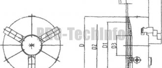
Fig. 1 - General view and main dimensions of a three-jaw lathe chuck.
Technical characteristics of the lathe chuck are given in Table 1
Table 1
| Name of parameters | Values |
| Outer diameter D, mm | 250 |
| Diameter of connecting belt D2, mm | 200H7 |
| Diameter of hole in housing D1, mm | 76 |
| Diameter of mounting holes, mm, D3 | 224 |
| Outer diameter of the product clamped in straight jaws, largest mm | 120 |
| Outer diameter of the product clamped in the return jaws, largest mm | 266 |
| Maximum permissible rotation speed, min ' | 2000 |
| Flange side height | 5 |
| Chuck height without jaws | 85 |
| Height of chuck assembly | 119 |
| Cartridge weight, kg | 29 |
| Fasteners | 6 M12 bolts |
Using a lathe chuck, using straight and reverse jaws, you can clamp workpieces in the following range of sizes
The straight cam is designed to secure the workpiece to the outer surface of the shaft or to the inner surface of the hole in the workpiece. The reverse cam is designed to secure the workpiece to the outer surface.
Accuracy characteristics of lathe chuck
Fig.2.1 - Lathe chuck at idle speed
the cartridge provides the following accuracy characteristics: Radial runout a – 0.045 mm;
End runout c – 0.025mm.
By securing the workpiece in the chuck, the following characteristics can be achieved:
Scheme I:
Rice. 2.2 - Lathe chuck with straight jaws attached to the outer surface of the workpiece.
range of fixed workpieces from 5 to 118mm;
Radial runout a at a length of 80 mm is 0.040 mm.
Scheme II:
Rice. 2.3 - Lathe chuck with workpiece fastened to the outer surface with reverse cams.
range of fixed workpieces from 77 to 188 mm and from 160 to 250 mm;
Radial runout a – 0.045mm;
End runout c – 0.025mm.
Scheme III:
Rice. 2.4 - Lathe chuck with workpiece fastened to the inner surface with straight jaws.
range of fixed workpieces from 62 to 174 mm and from 145 to 256 mm;
Radial runout a – 0.045mm;
End runout c – 0.025mm.
Types and classification of lathe chucks
Number of jaws in the chuck and their design
Lathe chucks are distinguished by the number of jaws: 2; 3; 4; 6
- 2-jaw self-centering chuck - used for clamping small asymmetrical workpieces (rebar, cast parts, forgings). Cartridges of this type have a fairly simple structure. Both manual and mechanized (pneumatic) chucks are used;
- 3-jaw self-centering chuck - usually used for fastening round and hexagonal workpieces, it is most widespread. The reason for its high popularity is the speed of centering and clamping of parts, which is especially important in small-scale production, where workpieces are changed very often;
- 4-jaw chuck with independent installation of jaws - used for fastening rectangular and asymmetrical parts, as well as square bars. The chuck has cams that move independently of each other, which provides it with wide capabilities;
- 6-jaw self-centering chuck - allows you to process thin-walled parts without deforming them. The gripping forces in a six-jaw lathe chuck are distributed evenly across the 6 jaws.
Cams are divided into direct and reverse:
- Straight jaws - clamp the part from above, along the outer surface;
- Reverse cams - clamp the part from the inside, the part must have a corresponding hole, be hollow, for example a pipe;
Chuck jaws of all types are manufactured in the following designs (GOST-2675-80):
- Solid cams - made from a single piece of steel with a tensile strength σB of at least 500 MPa and heat treatment of the clamping and rubbing working surfaces to a hardness of at least 43 HRCE;
- Prefabricated cams - consists of a rail (base) made of hardened steel, onto which an overhead cam, which can be made of non-hardened steel or non-ferrous metal, is attached with screws.
- Overhead jaws - used for fastening workpieces of large diameters;
Cartridge accuracy class
The cartridge accuracy class has five levels (GOST 1654-86):
- N - cartridge of normal accuracy;
- P - high-precision cartridge;
- B - high precision cartridge;
- A is a particularly high precision cartridge.
Material of body and parts of lathe chucks
Lathe chuck bodies (GOST 1654-86) must be made of the following materials:
- made of cast iron in terms of quality indicators no lower than those of the SCh 30 brand;
- made of steel with a tensile strength σB of at least 500 MPa and heat treatment of working surfaces to a hardness of at least 43 HRCE
Parts of lathe chucks must be made of steel with a tensile strength σB of at least 500 MPa and heat treatment of the working surfaces to a hardness of at least 57 HRCE;
A steel body is more expensive to produce than a cast iron one , but it allows you to significantly increase the number of revolutions of the cartridge.
Lathe chucks with wet jaws
To ensure accurate centering and perpendicularity of surfaces, so-called raw jaws are usually used, which are bored exactly along the diameter of the part to be fixed. These jaws include assembled jaws for a lathe chuck. The cams consist of a heat-treated base (rack) into which a threaded cylindrical pin is pressed. 2 cylindrical, hexagonal, rectangular or other shapes are attached to the base of the cam using screws 3.
In “raw” cams, it is possible to fasten parts on the outer final processed surface of which no traces of cam clamping are allowed, as well as to process thin-walled bushings. In the latter case, it is necessary to bore the cams so that they cover 90-95% of the surface of the workpiece.
"Raw" jaws are very effective at securing the threaded part of the part into the chuck. In this case, the corresponding thread is cut in the cams and the part to be processed is screwed into this thread, and then additionally clamped with the cams.
Type of drive used in the chuck
The chuck can have a manual drive or a mechanized drive .
- Manual drive - the part is clamped in the chuck by a person, usually using a key;
- Mechanized drive - automates the process of clamping and releasing the workpiece with a given force.
- Pneumatic drive - used mainly on automatic lathes
- Hydraulic drive - hydraulic chucks are more often used on machines with a chuck diameter greater than 200 mm.
- Electromechanical drive
If the part in the chuck is clamped manually, then this is a manually driven chuck and it is used in universal machines in conditions of individual and small-scale production.
Power-driven chucks provide good machine performance (high clamping and releasing speeds) and are used in mass production conditions.
Design of the clamping mechanism of lathe chucks
Lathe chucks have different jaw clamping mechanisms:
- The lead cartridge is the simplest type of cartridge. Designed for processing parts in centers
- The spiral self-centering jaw chuck is the most common type of design - usually 2, 3, 6 jaw chucks. The central part of the cartridge is a spiral disk. Centering occurs simultaneously with fastening;
- Independent jaw chuck - usually 4 jaw chucks. Convenient for fastening workpieces with a non-cylindrical shape, or when the axis of the cylindrical surface that is being processed does not coincide with the fastening axis;
- Lever chuck - fastening of the workpiece in a lever lathe chuck comes from a hydraulic drive, which moves the rod with the coupling. Lever chucks can be used in small-scale production;
- Wedge rack chuck - the workpiece is secured using a pneumatic or hydraulic drive. Wedge chucks demonstrate higher accuracy of workpiece centering than lever chucks;
- Collet chuck - for clamping a rod workpiece of a relatively small diameter. The advantages over other clamping devices are that the radial runout of the part, which is fixed in the collet, is so insignificant that they can be safely ignored. Collets are available as feeding and clamping;
- Drill chuck - used for fixing drills and other working tools in drilling machines;
- Diaphragm chuck - The diaphragm chuck provides the highest accuracy in centering parts. Elastic membranes are attached to the cartridge flange with bolts. Such a membrane has from 3 to 8 cams with replaceable jaws. A large number of cams on the diaphragm lathe chuck facilitates centering of the product with an accuracy of 0.05 millimeters and higher;
- Thermal Chuck - Thermal chucks are used for the same purposes as collet chucks. The difference lies in the method of clamping the tool: thermal chucks use a hot fit for this;
- Hydraulic chuck - The hydraulic chuck is an alternative to the thermal chuck. The tool is clamped in the hydraulic chuck due to fluid pressure;
- Eccentric chuck - 3-jaw eccentric chucks are used in large-scale production. They have high precision and clamping force. They can be re-adjusted to clamp another part relatively simply - by rearranging the mounted cams.
Method of attaching chucks to a lathe spindle
The method of attaching the chuck to the spindle depends on the type of spindle end and its design. In total there are 4 types of spindle ends with many standard sizes and designs. (See sidebar: Varieties of Lathe Spindle Nose Ends).
Lathe chucks have three types of fastening in accordance with GOST 2675-80 and one type in accordance with GOST 26651:
- GOST 2675-80 Type 1 - Cylindrical fit. The chuck is installed on the spindle through an intermediate flange (according to GOST 3889). The cartridge is centered on the intermediate flange through a cylindrical centering collar . The intermediate flange is either screwed onto the spindle thread (Version 1 of the intermediate flange) or installed on the centering cone of the spindle flange;
- GOST 2675-80 Type 2 - Fitting on the spindle flange taper. The chuck is installed on the centering cone of the spindle flange and secured with screws through the chuck body to the end of the spindle flange (type A) (GOST 12595);
- GOST 2675-80 Type 3 - Fit on the spindle flange taper. The chuck is installed on the centering cone of the spindle flange and secured through a rotary washer (GOST 12593);
- GOST 26651 — Fitting on the spindle flange taper. The chuck is installed on the centering cone of the spindle flange and secured with a Camlock clamp.
Varieties of front ends of lathe spindles. Designs and sizes
There are two types of spindle front ends:
- Threaded end of the spindle - in order to install the chuck on the spindle, an intermediate flange is required;
- The flanged end of the spindle has a conical guide - a centering cone that ensures more accurate centering of the chuck on the spindle. The chuck can be installed directly on the flanged end of the spindle (if the chuck has a centering cone) or through an intermediate flange in accordance with GOST 3889-80 (if the chuck has a centering collar).
Today there are four state standards regulating the design and dimensions of the front ends of spindles.
- GOST 16868 - Threaded spindle ends (Instead of OST 428)
- GOST 12595 - Type A flanged spindle ends and clamping device flanges
- GOST 12593 - Flanged ends of spindles for rotary washer and flanges of clamping devices
- GOST 26651 — Camlock-type flanged spindle ends and clamping devices
- GOST 3889 - Intermediate flanges for self-centering cartridges.
Front ends of lathe spindles
Device and principle of operation.
3.1. The design of a spiral rack lathe chuck is shown in Fig. 3.
Fig. 3 - Design of a spiral rack lathe chuck.
Cams 1 , 2 and 3 of the cartridge move simultaneously using disk 4 . On one side of this disk there are grooves (shaped like an Archimedean spiral) in which the lower protrusions of the cams are located, and on the other there is a cut bevel gear mated to three bevel gears 5 . When you turn one of the wheels 5 disk 4 (thanks to gearing) also turns and, by means of a spiral, simultaneously and evenly moves all three cams along the grooves of the cartridge body 6 .
Depending on the direction of rotation of the disk, the cams move closer to the center of the chuck or move away from it, clamping or releasing the part. The cams are made in three stages and are hardened to increase wear resistance.
Main design options
Lathe chucks are made of durable cast iron with a grade of at least SCh-30 or tool steel grades with a strength of at least 500 MPa.
There are various design options for lathe chucks; we will focus on the most commonly used in modern production:
- Lever chuck . The clamping occurs due to the displacement of the cams with clamps due to the action of a two-arm lever. The main characteristic is the number of cams and the degree of displacement on the working disk. The disadvantages include the difficulty of setting up, especially when carrying out non-standard operations. The cams can be adjusted by moving them simultaneously using a key or by individually adjusting each clamp. This type of equipment is usually used for roughing or semi-finishing.
- Wedge lathe chucks are an improved version of the lever clamp design. High accuracy of fixation is ensured by the presence of its own mechanical or pneumatic drive for each cam. It has the ability to fix the workpiece with an offset relative to the center of rotation, which makes it possible to process parts of complex configurations.
- Diaphragm lathe chucks. Provide the highest fixation accuracy thanks to membranes made of elastic material. The workpiece is fixed by turning off the hydraulic drive, which leads to expansion of the membrane. Characteristic features of the design are a large number of clamps with a relatively low compression force. Therefore, the main area of application of this type of equipment is finishing of parts at low rotation speeds.
Basic dimensions and designations
If we take the most common three-jaw chucks (GOST 2675-80), then the current standard provides for ten standard sizes determined by the overall diameter of the equipment: 80, 100, 125, 160, 200, 250, 315, 400, 500 and 630 mm (see Table 1)
Depending on the method of installation on the spindle, the equipment is divided into three types:
- With belt and fixation by means of an auxiliary flange (Type 1);
- With fixation through a flange at the end of the spindle under a rotary washer (Type 2);
- With fixation through a flange at the end of the spindle (Type 3).
There is a unified designation system for the main parameters of the cartridge, consisting of 8 numbers and a letter indicating the accuracy class of the equipment. Using the table in GOST 2675-80 based on product labeling, you can determine:
- Number of clamps;
- Product diameter;
- Basic dimensions;
- Type of fastening of equipment to the spindle;
- Execution of clamps;
- Accuracy class.
So, for example, Chuck 7100-0032-P GOST 2675-80 designates the second type, diameter 200 mm, mounting on a spindle with standard size 5, prefabricated jaws and increased accuracy class (P).
Three-jaw self-centering lever chucks
The design of the chucks allows independent adjustment of the cams using screws 1 with vernier division.
The ratio of the arms of the transmission lever 2 is 1:3.5. The chucks are installed on the adapter flange of the lathe spindle.
The drive is pneumatic.
Dimensions in mm
| d | D | D1 (additional trip for A) | D2 | D3 | n | n1 | L | B (additional deflection according to C) | c | l | l1 | |||||
| min | max | |||||||||||||||
| 10 | 180 | 250 | 210 | 171,5 | 226 | 160 | 95 | 110 | 34 | 80 | 13 | 25 | ||||
| 10 | 280 | 350 | 270 | 235 | 290 | 170 | 100 | 130 | 36 | 95 | 15 | 35 | ||||
| r2 (additional deactivation according to C3) | l3 | d (additional deactivation according to Al) | b | b1 (additional deactivation according to A3) | h | h1 | d1 | d2 | d3 | d4 | Move fist ka | |||||
| 20 | 30 | 10 | 16 | 20 | 7 | 6 | M39X2 | M16 | M12 | M12 | 5 | |||||
| 25 | 40 | 14 | 24 | 22 | 11 | 10 | M68x 2 | M20 | M16 | M12 | 6 | |||||