Tensile strength
PP - we will use this abbreviation, and we can also talk about the official combination “temporary resistance” - this is the maximum mechanical force that can be applied to an object before its destruction begins. In this case, we are not talking about chemical effects, but we mean that heating, unfavorable climatic conditions, and a certain environment can either improve the properties of the metal (as well as wood, plastic) or worsen it.
No engineer uses extreme values when designing, because it is necessary to leave a permissible error - for environmental factors, for the duration of operation. We told you what is called tensile strength, now let’s move on to the specifics of the definition.
How is the strength test performed?
Initially there were no special events. People took an item, used it, and as soon as it broke, they analyzed the breakdown and reduced the load on a similar product. Now the procedure is much more complicated, however, until now the most objective way to find out PP is the empirical way, that is, experiments and experiments.
All tests are carried out under special conditions with a large amount of precise equipment that records the condition and characteristics of the experimental material. Usually it is fixed and experiences various influences - tension, compression. They are performed by instruments with high precision - every thousandth of a newton of the applied force is noted. At the same time, each deformation is recorded as it occurs. Another method is not laboratory, but computational. But usually mathematical analysis is used in conjunction with testing.
Definition of the term
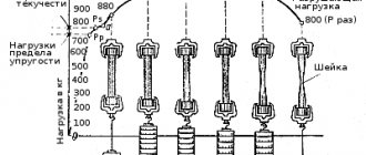
The sample is stretched on a testing machine. In this case, first it lengthens in size, and the cross-section becomes narrower, and then a neck is formed - the place where the thinnest diameter is, this is where the workpiece will rupture. This is true for ductile alloys, while brittle alloys, such as cast iron and hard steel, stretch very slightly without necking. Let's take a closer look at the video:
Tensile (compressive) strength calculations
Let's start with, perhaps, the simplest type of tensile (compressive) deformation. The stress under central tension (compression) can be obtained by dividing the longitudinal force by the cross-sectional area, and the strength condition looks like this:
where sigma in square brackets is the permissible stress. Which can be obtained by dividing the ultimate stress by the safety factor:
Moreover, different values are taken as the ultimate stress for different materials. For ductile materials, for example, for low-carbon steel (St2, St3), the yield strength is taken, and for brittle materials (concrete, cast iron), the tensile strength (tensile strength) is taken as the ultimate stress. These characteristics are obtained by testing samples in tension or compression on special machines that record the characteristics in the form of a diagram.
The safety factor is selected by the designer based on his personal experience, the purpose of the part being designed and the scope of application. Typically, it varies from 2 to 6.
If it is necessary to select the dimensions of the section, the area is expressed as follows:
Thus, the minimum cross-sectional area under central tension (compression) will be equal to the ratio of the longitudinal force to the permissible stress.
Tensile strength of steel
Steel structures have long replaced other materials, as they have excellent performance characteristics - durability, reliability and safety. Depending on the technology used, it is divided into brands. From the most common with a PP of 300 MPa, to the hardest with a high carbon content - 900 MPa. This depends on two indicators:
- What heat treatment methods were used - annealing, hardening, cryotreatment.
- What impurities are contained in the composition. Some are considered harmful, they are discarded for the purity of the alloy, and others are added to strengthen them.
General information and characteristics of steels
From the designer’s point of view, the physical and mechanical parameters of steel are of greatest importance for alloys operating under normal conditions. In some cases, when the product is to operate under conditions of extremely high or low temperatures, high pressure, high humidity, or under the influence of aggressive environments, the chemical properties of steel become equally important. Both the physical-mechanical and chemical properties of alloys are largely determined by their chemical composition.
Influence of carbon content on the properties of steels
As the percentage of carbon increases, the plasticity of the substance decreases with a simultaneous increase in strength and hardness. This effect is observed up to approximately 1% share, then a decrease in strength characteristics begins.
Increasing the proportion of carbon also increases the threshold of cold capacity; this is used to create frost-resistant and cryogenic grades.
The influence of carbon on the mechanical properties of steel
An increase in the C content leads to a deterioration in casting properties and negatively affects the ability of the material to be machined.
Manganese and silicon additives
Mn is contained in most grades of steel. It is used to displace oxygen and sulfur from the melt. Increasing the Mn content to a certain limit (2%) improves machinability parameters such as ductility and weldability. After this limit, further increases in content lead to the formation of cracks during heat treatment.
The influence of silicon on the properties of steels
Si is used as a deoxidizer used in the smelting of steel alloys and determines the type of steel. Quiet high-carbon grades should contain no more than 0.6% silicon. For semi-quiet brands, this limit is even lower - 0.1%.
When producing ferrites, silicon increases their strength parameters without reducing their ductility. This effect persists up to the 0.4% threshold.
The influence of alloying additives on the properties of steel
In combination with Mn or Mo, silicon promotes an increase in hardenability, and together with Cr and Ni increases the corrosion resistance of alloys.
Nitrogen and oxygen in the alloy
These gases, the most common in the earth's atmosphere, have a harmful effect on strength properties. The compounds they form in the form of inclusions in the crystalline structure significantly reduce strength parameters and ductility.
Fatigue of steel
The second name is endurance limit. It is denoted by the letter R. This is a similar indicator, that is, it determines what force can act on an element, but not in a single case, but in a cycle. That is, certain pressures are applied to the experimental standard cyclically, over and over again. The average number of repetitions is 10 to the seventh power. This is exactly how many times the metal must withstand the impact without deformation or loss of its characteristics.
If you carry out empirical tests, it will take a lot of time - you need to check all the force values, applying it over many cycles. Therefore, the coefficient is usually calculated mathematically.
Endurance limit or fatigue limit (σR)
The ability of a material to withstand loads that cause cyclic stress. This strength parameter is defined as the maximum stress in a cycle at which fatigue failure of the product does not occur after an indefinitely large number of cyclic loads (the basic number of cycles for steel is Nb = 10 7). The coefficient R (σR) is taken to be equal to the cycle asymmetry coefficient. Therefore, the fatigue limit of the material in the case of symmetric loading cycles is designated as σ-1, and in the case of pulsating ones - as σ0.
Note that fatigue tests of products are very long and labor-intensive; they involve the analysis of large volumes of experimental data with an arbitrary number of cycles and a significant scatter of values. Therefore, special empirical formulas are most often used that connect the endurance limit with other strength parameters of the material. The most convenient parameter is considered to be the tensile strength.
For steels, the bending endurance limit is usually half the tensile strength: For high-strength steels, you can take:
For ordinary steels during torsion under conditions of cyclically changing stresses, the following can be accepted:
The above ratios should be used with caution, because they were obtained under specific loading conditions, i.e. during bending and torsion. However, when testing in tension-compression, the endurance limit becomes approximately 10-20% less than in bending.
Proportionality limit
This is an indicator that determines the duration of the loads applied to the deformation of the body. In this case, both values should change to different degrees according to Hooke’s law. In simple words: the greater the compression (tension), the more the sample is deformed.
The value of each material lies between absolute and classical elasticity. That is, if the changes are reversible after the force ceases to act (the shape becomes the same - for example, compression of a spring), then such parameters cannot be called proportional.
How are the properties of metals determined?
They check not only what is called tensile strength, but also other characteristics of steel, for example, hardness. The tests are carried out as follows: a ball or cone made of diamond, the most durable rock, is pressed into the sample. The stronger the material, the smaller the mark left. Deeper, wider-diameter prints are left on soft alloys. Another experience - for a blow. The impact occurs only after a pre-made cut on the workpiece. That is, the destruction is checked for the most vulnerable area.
Mechanical properties
There are 5 characteristics:
- The tensile and tensile strength of steel is temporary resistance to external forces, stress arising internally.
- Plasticity is the ability to deform, change shape, but maintain the internal structure.
- Hardness – willingness to meet harder material without causing significant damage.
- Impact strength is the ability to resist impacts.
- Fatigue is the duration of preservation of qualities under the influence of cyclic loads.
Meaning of the term
The tensile strength of the material is abbreviated as PP. It is also permissible to use the expression “temporary resistance”. To indicate the tensile strength, the letters R or σ B (sigma) are used. The unit of measurement is megapascal (MPa). The indicator means the permissible amount of force that can act on an object before it begins to collapse. We are talking about mechanical effects, but it should be taken into account that chemical factors can change the initial properties of the material, including affecting the PP. Non-mechanical loads include the following:
- heating;
- cooling;
- weather conditions (wind, precipitation, humidity);
- aggressive environment.
The formula for tensile strength is written as follows: R = 0.64 (P/F), where F is the surface area of the object's split, and P is the breaking load. When designing, you cannot rely on extreme values, so engineers leave tolerances for various factors, as well as for the period of operation. This means that during construction a material is used whose PP exceeds the design stress.
Initially, the ability of an element to withstand loads was determined experimentally. The material was used without knowing how it would behave during operation, and after a breakdown it was replaced with a more durable one. Over time, we moved on to experiments and tests, and still the most accurate way to find the tensile and tensile strength remains empirical.
Research is carried out in laboratory conditions, using precise technology. The devices record the characteristics of the material and how they change under loads of different magnitudes. As a rule, strength is measured as follows: an object is rigidly fixed and an impact is exerted on it.
First, the fixed element is stretched. It becomes longer, and an isthmus forms in one place, and this is where the workpiece will rupture. Not all materials behave this way, only viscous ones. Cast iron, steel and other brittle alloys stretch only slightly. As the load increases, they crack and collapse along inclined planes. No necks are formed.
The force applied at each moment is measured to the nearest thousandth of a newton. At the same time, the size and nature of the deformation are determined. The data is checked against tables.
The second method is mathematical analysis. It lies in the fact that strength is determined using complex calculations. However, without testing, the data obtained by calculation cannot be considered complete. The fact is that in practice a substance may behave differently.
Strength classes and their designations
All categories are written down in regulatory documents - GOSTs, according to which all Russian entrepreneurs produce any rolled metal and other metal products. Here is the correspondence between the designation and parameter in the table:
| Class | Tensile strength, N/mm2 |
| 265 | 430 |
| 295 | 430 |
| 315 | 450 |
| 325 | 450 |
| 345 | 490 |
| 355 | 490 |
| 375 | 510 |
| 390 | 510 |
| 440 | 590 |
We see that for some classes the PP indicators remain the same, this is explained by the fact that, with equal values, their fluidity or relative elongation may differ. Depending on this, different maximum thickness of rolled metal is possible.
Parameter classification
The material has temporary resistance in response to impacts of various types, so the characteristic is classified into several groups. Forces to which the workpiece or structural element is subjected:
- Stretching. The product is pulled by the edges using a special machine.
- Torsion. The object is placed in conditions under which the rotating shaft operates.
- Bend. The workpiece is bent and unbent in several directions.
- Compression. The material is pressed alternately from different sides.
For the same material, the PP may vary. An example is steel. It is used more often than other alloys because steel structures have proven to be the strongest, most durable, and most resistant to the elements. At the same time, they are reliable and do not emit harmful substances into the atmosphere.
There are several grades of steel. They are produced using different technologies, and depending on this, the characteristics of the workpieces and structures differ. For conventional brands, the PP is 300 MPa. As the carbon content increases, the strength increases. The hardest grades have a value of 900 MPa. Factors on which strength characteristics depend:
- the amount of useful and undesirable impurities;
- method of heat treatment (cryotreatment, hardening, annealing).
Specific strength formula
R with the index “y” is the designation of this parameter in physics. It is calculated as PP (in writing – R) divided by density – d. That is, this calculation has practical value and takes into account theoretical knowledge about the properties of steel for use in life. Engineers can tell how the temporary resistance changes depending on the mass and volume of the product. It is logical that the thinner the sheet, the easier it is to deform.
The formula looks like this:
Ry = R/d
Here it would be logical to explain how the specific tensile strength is measured. In N/mm2 - this follows from the proposed calculation algorithm.
Elastic moduli
The main characteristics of the elastic properties of materials are Young's modulus E (modulus of elasticity of the first kind, modulus of elasticity in tension), modulus of elasticity of the second kind G (modulus of elasticity in shear) and Poisson's ratio μ (transverse deformation coefficient).
Young's modulus E shows the ratio of normal stresses to relative strains within the limits of proportionality
Young's modulus is also determined empirically when testing standard tensile specimens. Since the normal stresses in the material are equal to the force divided by the initial cross-sectional area:
σ = Р/Fо (318.3.1), (317.2)
and relative elongation ε - the ratio of absolute deformation to the initial length
εpr = Δl/lo (318.3.2)
then Young’s modulus according to Hooke’s law can be expressed as follows
E = σ/εpr = Plo/FoΔl = tanα (318.3.3)
Figure 318.2. Stress diagrams of some metal alloys
Poisson's ratio μ shows the ratio of transverse to longitudinal strains
Under the influence of loads, not only does the length of the sample increase, but also the area of the cross-section under consideration decreases (if we assume that the volume of material in the region of elastic deformation remains constant, then an increase in the length of the sample leads to a decrease in the cross-sectional area). For a sample having a circular cross-section, the change in cross-sectional area can be expressed as follows:
εpop = Δd/do (318.3.4)
Then Poisson's ratio can be expressed by the following equation:
μ = εpop/εpr (318.3.5)
The shear modulus G shows the ratio of tangential stresses t to the shear angle
The shear modulus G can be determined experimentally by testing specimens for torsion.
During angular deformations, the section under consideration does not move linearly, but at a certain angle—the shear angle γ to the initial section. Since the shear stress is equal to the force divided by the area in the plane in which the force acts:
t = P/F (318.3.6)
and the tangent of the angle of inclination can be expressed as the ratio of the absolute deformation Δl to the distance h from the place where the absolute deformation was recorded to the point relative to which the rotation was made:
tgγ = Δl/h (318.3.7)
then at small values of the shear angle the shear modulus can be expressed by the following equation:
G = m/γ = Ph/FΔl (318.3.8)
Young's modulus, shear modulus and Poisson's ratio are related to each other by the following relationship:
E = 2(1 + μ)G (318.3.9)
The values of the constants E, G and µ are given in table 318.1
Table 318.1. Approximate values of the elastic characteristics of some materials
Note: Elastic moduli are constant values, however, manufacturing technologies for various building materials change and more accurate values of elastic moduli should be clarified according to currently valid regulatory documents. The modulus of elasticity of concrete depends on the class of concrete and therefore is not given here.
Elastic characteristics are determined for various materials within the limits of elastic deformations limited on the stress diagram by point A. Meanwhile, several more points can be identified on the stress diagram:
Elastic limit Ru
Normal stresses in the cross section of the sample when the elastic limit is reached will be equal to:
σу = Ru/Fo (318.2.4)
The elastic limit limits the area in which the appearing plastic deformations are within a certain small value, normalized by technical conditions (for example, 0.001%; 0.01%, etc.). Sometimes the elastic limit is designated according to the tolerance σ0.001, σ0.01, etc.
Yield strength RT
σт = Рт/Fo (318.2.5)
Limits the area of the diagram in which the deformation increases without a significant increase in load (yield state). In this case, a partial rupture of internal bonds occurs throughout the entire volume of the sample, which leads to significant plastic deformations. The sample material is not completely destroyed, but its initial geometric dimensions undergo irreversible changes. On the polished surface of the samples, yield figures are observed - shear lines (discovered by Professor V.D. Chernov). For different metals, the angles of inclination of these lines are different, but are in the range of 40-50o. In this case, part of the accumulated potential energy is irreversibly spent on the partial rupture of internal bonds. When testing tensile strength, it is customary to distinguish between the upper and lower yield limits - respectively, the highest and lowest stresses at which plastic (residual) deformation increases at an almost constant value of the acting load.
The stress diagrams indicate the lower yield strength. It is this limit for most materials that is taken as the standard resistance of the material.
Some materials do not have a pronounced yield plateau. For them, the conditional yield strength σ0.2 is taken to be the stress at which the residual elongation of the sample reaches a value of ε ≈0.2%.
4. Tensile strength Pmax (temporary strength)
Normal stresses in the cross section of the sample when the ultimate strength is reached will be equal to:
σв = Рmax/Fo (318.2.6)
After overcoming the upper yield limit (not shown in the stress diagrams), the material again begins to resist loads. At maximum force Pmax, complete destruction of the internal bonds of the material begins. In this case, plastic deformations are concentrated in one place, forming a so-called neck in the sample.
The stress at maximum load is called the tensile strength or tensile strength of the material.
Tables 318.2 - 318.5 provide approximate values of tensile strength for some materials:
Table 318.2 Approximate compressive strength limits (tensile strengths) of some building materials.
Note: For metals and alloys, the value of tensile strength should be determined in accordance with regulatory documents. The value of temporary resistances for some steel grades can be found here.
Table 318.3. Approximate strength limits (tensile strengths) for some plastics
Table 318.4. Approximate tensile strengths for some fibers
Table 318.5. Approximate strength limits for some wood species
Destruction of PP material
If you look at the stress diagram, it seems that the destruction of the material occurs as the load decreases. This impression is created because as a result of the formation of a “neck,” the cross-sectional area of the sample in the area of the “neck” changes significantly. If you construct a stress diagram for a sample made of low-carbon steel depending on the changing cross-sectional area, you will see that the stresses in the section under consideration increase to a certain limit:
Figure 318.3. Stress diagram: 2 - in relation to the initial cross-sectional area, 1 - in relation to the changing cross-sectional area in the neck area.
Nevertheless, it is more correct to consider the strength characteristics of the material in relation to the area of the original section, since strength calculations rarely include changes in the original geometric shape.
One of the mechanical characteristics of metals is the relative change ψ of the cross-sectional area in the neck area, expressed as a percentage:
ψ = 100(Fo - F)/Fo (318.2.7)
where Fo is the initial cross-sectional area of the sample (cross-sectional area before deformation), F is the cross-sectional area in the neck region. The higher the value of ψ, the more pronounced the plastic properties of the material are. The lower the value of ψ, the greater the fragility of the material.
If you add up the torn parts of the sample and measure its elongation, it turns out that it is less than the elongation in the diagram (by the length of the segment NL), since after rupture the elastic deformations disappear and only plastic deformations remain. The amount of plastic deformation (elongation) is also an important characteristic of the mechanical properties of the material.
Beyond elasticity, up to fracture, total deformation consists of elastic and plastic components. If you bring the material to stresses exceeding the yield strength (in Fig. 318.1, some point between the yield strength and the tensile strength), and then unload it, then plastic deformations will remain in the sample, but when reloaded after some time, the elastic limit will become higher, since in this case, a change in the geometric shape of the sample as a result of plastic deformations becomes, as it were, the result of the action of internal connections, and the changed geometric shape becomes the initial one. This process of loading and unloading material can be repeated several times, and the strength properties of the material will increase:
Figure 318.4. Stress diagram during work hardening (inclined straight lines correspond to unloading and repeated loading)
This change in the strength properties of a material, obtained through repeated static loading, is called work hardening. However, when the strength of a metal increases by cold hardening, its plastic properties decrease and its fragility increases, so relatively small hardening is usually considered useful.
Using the properties of metals
Two important indicators - plasticity and PP - are interrelated. Materials with a large first parameter degrade much more slowly. They change their shape well and are subjected to various types of metal processing, including die stamping - that’s why car body elements are made from sheets. With low ductility, alloys are called brittle. They can be very hard, but at the same time have poor stretching, bending and deformation, for example, titanium.
Resistance
There are two types:
- Regulatory - prescribed for each type of steel in GOSTs.
- Calculated – obtained after calculations in a specific project.
The first option is rather theoretical; the second is used for practical tasks.
Ways to increase strength characteristics
There are several ways to do this, two main ones:
- addition of impurities;
- heat treatment, for example, hardening.
Sometimes they are used together.
General information about steels
All of them have chemical and mechanical properties. Below we’ll talk in more detail about ways to increase strength, but first, let’s present a diagram showing all the varieties:
Also watch a more detailed video:
All of them have chemical and mechanical properties. Below we’ll talk in more detail about ways to increase strength, but first, let’s present a diagram showing all the varieties:
Carbon
The higher the carbon content of a substance, the higher the hardness and the lower the ductility. But the composition should not contain more than 1% of the chemical component, since a larger amount leads to the opposite effect.
Manganese
A very useful additive, but with a mass fraction of no more than two percent. Mn is usually added to improve machinability. The material becomes more susceptible to forging and welding. This is due to the displacement of oxygen and sulfur.
Silicon
Effectively increases strength characteristics without affecting ductility. The maximum content is 0.6%, sometimes 0.1% is enough. Combines well with other impurities; together, they can increase corrosion resistance.
Nitrogen and oxygen
If they get into the alloy, but worsen its characteristics, they try to get rid of them during manufacturing.
Alloying Additives
You can also find the following impurities:
- Chrome – increases hardness.
- Molybdenum – protects against rust.
- Vanadium – for elasticity.
- Nickel – has a good effect on hardenability, but can lead to brittleness.
These and other chemicals must be used in strict proportions according to the formulas. In the article we talked about tensile strength (short-term resistance) - what it is and how to work with it. They also gave several tables that you can use while working. To finish, let's watch the video:
To clarify the information you are interested in, please contact our managers by phone;; 8 (800) 707-53-38. They will answer all your questions.
Temporary resistance
Temporary resistance at room temperature changes in two ways as a result of prolonged operation at high temperatures. At high values in the initial state, it is greatly reduced in operation; at values close to the lower limit according to technical conditions, the temporary resistance practically does not change. [1]
The tensile strength must not be lower than the minimum permissible limit for the tensile strength of the base metal according to GOST or technical specifications for the corresponding semi-finished products (strips, pipes, etc.) from steel of this grade. [2]
Tensile strength and bending strength decrease due to an increase in the fragility of the metal base and the presence of large internal stresses in the samples caused by hardening. In this state, low-carbon cast iron, like other cast irons with a lamellar form of graphite, after quenching has low erosion resistance. This is explained by the overstress of individual micro-areas, especially in places where graphite inclusions accumulate, where high stresses are concentrated. In this case, the metal base of cast iron is destroyed quickly without an incubation period. [3]
Temporary tensile strength must be at least 20 kg / ur2 after 2 days. [4]
Temporary resistance (a) characterizes the maximum stress preceding the failure of the sample. There are conditional and true voltages. Conditional stress is the ratio of the load value to the original cross-section of the sample; true - to the cross section that the sample acquired by the time it reached a given load. Tensile diagrams of ductile metals with nominal stresses differ from diagrams with true stresses. [5]
Tensile strength (tensile strength) 0V (vpch, 0v, 0n), kgf/mm2 – stress corresponding to the greatest load that precedes the destruction of the sample, and related to the initial area (F0) of its cross section before testing. [6]
Temporary resistance to peeling by gluing in a dry state is determined on the samples shown in Fig. [7]
The temporary chipping resistance of the adhesive joint must meet the requirements of the technical specifications for the adhesive. [8]
The tensile strength in bending significantly depends on the quality of the surface preparation of the samples. [9]
Tensile strength and relative elongation after rupture are determined in accordance with regulatory and technical documentation. [10]
Tensile strength and relative elongation correspond to those indicated, in table. [eleven]
The tensile strength of the metal of welded seams at 20 C must correspond to the values established in the regulatory and technical documentation for the base metal. [12]
Tensile strength is determined for tapes with a thickness of 0-3 mm or more, relative elongation - for tapes with a thickness of 0-5 mm or more. [14]
Tensile strength increases with increasing tin content. At a high concentration of tin, due to the presence in the structure of a significant amount of eutectoid containing the brittle compound Cu31Sn8, the temporary resistance sharply decreases. The relative elongation increases slightly when the bronze content is 4–6% Sn, but when a eutectoid is formed, it drops significantly. Tin bronzes are usually alloyed with Zn, Fe, P, Pb, Ni and other elements. Zinc improves the technological properties of bronze and reduces the cost of bronze. It improves casting properties, increases hardness, strength, wear resistance, elasticity and anti-friction properties. Nickel increases the mechanical properties, corrosion resistance and density of castings and reduces segregation. Iron refines the grain, but worsens the technological properties of bronzes and corrosion resistance. [15]
Mechanical properties
characterize the ability of a material to resist external mechanical influences. The main mechanical properties include strength, ductility, hardness, impact strength, etc.
Main characteristics of the mechanical properties of non-ferrous metal alloys:
Carbon and low-alloy steels of increased and high strength are used for steel and reinforced concrete structures. Steels for structures are classified according to the smelting method, deoxidation technology, chemical composition, method of hardening, quality and purpose, as well as strength.
According to the method of smelting, steels are divided into open-hearth, oxygen-converter and Bessemer; according to deoxidation technology - into calm, semi-calm and boiling (including clogged boiling); according to the method of hardening - cold-deformed and heat-treated (heat-strengthened).
Steel is divided according to purpose: into general purpose steel - carbon hot-rolled of ordinary quality and steel for various purposes - carbon hot-rolled of high quality (low alloy) and high strength.
The following steel strength classes have been established (according to the values of tensile strength and yield strength): C 38/23, C 44/30, C 46/34, C 52/40, C 60/45, C 70/60.
Limit of proportionality σпс – stress at which the deviation from the linear relationship between stresses and elongations reaches a certain value established by technical conditions or standard (for example, a decrease in the tangent of the tangent to the tensile diagram relative to the strain axis by 20 or 33% of its original value).
Elastic limit σуп – stress at which residual elongations reach a certain small value established by technical specifications or standard (for example, 0.001; 0.01%, etc.). Sometimes the elastic limit is designated according to the tolerance σ0.001; σ0.01, etc.
Read also: Band saw blade speed
The yield strength σt for materials with a yield plateau (low-carbon steel) is defined as the stress corresponding to the lowest point of the yield plateau; for materials that do not have a yield plateau, the conditional yield strength σ0.2 is determined - the stress at which the residual elongation of the sample reaches 0.2%.
Tensile strength (tensile strength) σв – stress equal to the ratio of the greatest load preceding the destruction of the sample to the original cross-sectional area of the sample. Tensile strength can be identified with ultimate strength only for brittle materials that fail without necking. For plastic materials, this is a characteristic of a peculiar loss of stability during tension, i.e., a characteristic of resistance to significant plastic deformations.
Relative elongation at break δ is the ratio (usually in %) of the increase in the estimated length of the sample after break to its initial value. For a long round sample (lcalc=10d) – δ10; for a short sample (lcalc=5d) – δ5.
Relative contraction at rupture ψ is the ratio of the reduction in the area of the smallest cross-section of the sample (after rupture) to the initial cross-sectional area of the sample.
Conditional bending yield strength σт.и is the normal stress, calculated conventionally using formulas for elastic bending, at which the residual elongation of the most stressed outer fiber reaches 0.2% or another value of the same order in accordance with the requirements of the technical specifications.
Temporary resistance (ultimate strength) during bending σв.и – normal stress, calculated conventionally using formulas for elastic bending and corresponding to the highest load preceding the fracture of the sample.
Conditional yield strength in torsion τ0.2, τt – shear stress, calculated conventionally using formulas for elastic torsion, at which residual elongation or shear deformations along the surface of the sample reach 0.2% or another value of the same order in accordance with the requirements of the technical specifications.
Temporary resistance (ultimate strength) in torsion τв – tangential stress, calculated conventionally using formulas for elastic torsion and corresponding to the highest torsional moment preceding the destruction of the sample.
Brinell hardness HB is the hardness of a material, determined by pressing a steel ball into it and calculated as the quotient of the load divided by the surface of the resulting print. For some materials there is an approximately direct proportionality between the hardness of the NV and the tensile strength; for example, for carbon steels σв ≈ 0.36 НВ.
Rockwell hardness HRC, HRB - the hardness of a material, determined by pressing a steel ball or a diamond cone of standard sizes and measured in conventional units using different scales according to the increment of the remaining immersion depth when moving from a small standard load to a large one.
Vickers hardness HV is the hardness of the material, determined by indenting a diamond tetrahedral pyramid of standard sizes and calculated as the quotient of the standard load divided by the lateral surface of the resulting imprint.
Creep limit (conditional) - a long-term stress at which the rate or deformation of creep over a certain period of time at a given temperature does not exceed the value established by the technical specifications.
Long-term strength limit is the stress that causes the destruction of a sample after a specified period of its continuous operation at a certain temperature.
Fatigue limit is the greatest periodically varying stress that a material can withstand without destruction at a large number of cycles specified by technical conditions (for example, 10 6; 10 7; 10 8). Designated for a symmetrical cycle σ-1 (bending), σ-1p (tension-compression), τ-1 (torsion), for a pulsating cycle (stresses change from zero to maximum) σ, σ0p and τ, respectively.
Impact strength ak is the work expended on the destruction of a sample during impact bending, related to the working cross-section of the sample.
Elastic aftereffect: direct - a gradual increase in deformation after a rapid cessation of load growth; the opposite is the persistence or slow decrease in deformation after rapid removal of the load or stopping unloading.
Hardening is the hardening of metal that occurs due to plastic deformation during cold working processes (cold rolling, drawing, drawing).
Aging (mechanical) is a spontaneous long-term change in the mechanical properties of steel after hardening, caused by phase transformations. A distinction is made between natural aging, which occurs at room temperature, and artificial aging, which occurs at elevated temperatures.
The fracture of steel is possible ductile (plastic) - from shear, brittle - from separation. In both cases, destruction consists of a violation of integrity, a rupture. A discontinuity can occur under the condition of accumulation of energy corresponding to the value of the surface energy on the surfaces of the discontinuity, and in accordance with this, the distance between atoms must reach critical values at which a breakdown of the connection between them occurs.
The work of destruction is the value of the entire area of the tensile diagram of the sample in P-∆l coordinates; elastic work – the area of the elastic part of the same diagram; specific work – work per unit volume of the working part of the sample and corresponding to the area of the tensile diagram in σ-ε coordinates.
The specific gravity in the calculations is taken equal to 7.85 for steel, 7.2 for cast iron; the specific gravity of steel containing 0.1% C is 7.06 (in the liquid state).
Read also: Axial piston pump diagram
The elastic modulus E of steel and other elastic constants are practically independent of the grain size, structure, ratios between the volumes of ferrite and pearlite, carbon content and other alloying additives.
Modulus of elasticity for rolled steel, casting, hot-rolled reinforcement from steel grades St.5 and St.3 E=2.1·10 6 kg/cm 2 ; for steels 30ХГ2С and 25Г2С E=2·10 6 kg/cm 2. For cold-drawn round and periodic wire profiles, as well as for cold-flattened reinforcement, E = 1.8·10 6 kg/cm 2.
For bundles and strands of high-strength wire (with parallel arrangement of wires) E = 2·106 kg/cm 2 ; for spiral steel ropes and ropes (cables) with a metal core E=1.5·10 4 kg/cm 2 ; for cables with an organic core E = 1.3 10 6 kg/cm 2.
For gray cast iron castings of grades SCh28-48, SCh24-44, SCh21-40 and SCh18-36 E=1·10 6 kg/cm 2 .
Shear modulus for rolled steel G=8.4·10 6 kg/cm 2 .
Poisson's ratio (lateral strain ratio) μ=0,3.
Methods for determining the mechanical properties of metals are divided into:
– static, when the load increases slowly and smoothly (tensile, compression, bending, torsion, hardness tests);
– dynamic, when the load grows at high speed (impact bending tests);
– cyclic, when the load changes repeatedly in magnitude and direction (fatigue tests).
1. Tensile test
Tensile testing determines the tensile strength
(σв),
yield strength
(σт),
relative elongation
(δ) and
relative contraction
(ψ). Tests are carried out on tensile testing machines using standard samples with cross-sectional area Fo and working (calculated) length lo. As a result of the tests, a tensile diagram is obtained (Fig. 1). The abscissa axis indicates the value of the deformation, and the ordinate axis indicates the value of the load that is applied to the sample.
Ultimate strength (σв) is the maximum load that the material can withstand without destruction, related to the initial cross-sectional area of the sample (Pmax/Fo).
Didn't find what you were looking for? Use the search:
Best sayings:
What kind of mathematicians are you if you can’t password protect properly.
8256 – | 7223 – or read all.
91.146.8.87 © studopedia.ru Not the author of the materials posted. But it provides free use. Is there a copyright violation? Write to us | Feedback.
Disable adBlock! and refresh the page (F5)
very necessary
Tensile strength
- this is the same as the temporary resistance of the material.
But despite the fact that it is more correct to use the term temporary resistance
, the concept of tensile strength has taken root better in technical colloquial speech. At the same time, in regulatory documentation and standards the term “temporary resistance” is used.
Strength
- this is the resistance of a material to deformation and destruction, one of the main
mechanical properties
. In other words, strength is the ability of materials to withstand certain influences (loads, temperature, magnetic and other fields) without collapsing.
To the tensile strength characteristics
include normal modulus of elasticity, proportional limit, elastic limit, yield strength and tensile strength (tensile strength).
Tensile strength
– this is the maximum mechanical stress above which destruction of the material subject to deformation occurs; tensile strength is designated σB and is measured in kilograms of force per square centimeter (kgf/cm2), and is also indicated in megapascals (MPa).
There are:
- tensile strength,
- compressive strength,
- bending strength,
- torsional strength.
Short-term strength (MPa)
determined using tensile tests, deformation is carried out until failure. Tensile tests are used to determine tensile strength, elongation, elastic limit, etc. Long-term strength tests are intended primarily to assess the possibility of using materials at high temperatures (long-term strength, creep); as a result, σB/Zeit is determined - the limit of limited long-term strength for a given service life. [1]
Physics of strength
founded by Galileo: summarizing his experiments, he discovered (1638) that in tension or compression, the fracture load
P
for
a given material depends only on the cross-sectional area
F. This is how a new physical quantity appeared - stress σ=P
/
F
- and a physical constant of the material: fracture stress [4].
Physics of fracture as a fundamental science of the strength of metals
arose in the late 40s of the XX century [5]; this was dictated by the urgent need to develop scientifically based measures to prevent the increasingly frequent catastrophic destruction of machines and structures. Previously, in the field of strength and destruction of products, only classical mechanics was taken into account, based on the postulates of a homogeneous elastic-plastic solid body, without taking into account the internal structure of the metal. The physics of destruction also takes into account the atomic-crystalline structure of the metal lattice, the presence of defects in the metal lattice and the laws of interaction of these defects with elements of the internal structure of the metal: grain boundaries, second phase, non-metallic inclusions, etc.
Great influence on the strength of the material
is influenced by the presence of surfactants in the environment that can be strongly adsorbed (moisture, impurities); the tensile strength decreases.
Increasing the strength of a metal is caused by targeted changes in the metal structure, including modification of the alloy.
Read also: Drawing of a dagger with dimensions
Educational film about the strength of metals (USSR, year of release: