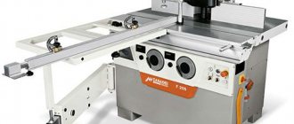
Milling is in demand in various areas of industry. There are several types of industrial equipment for working with metal. In our article we will talk about a vertical milling machine. Before using it, you need to study the design and technical characteristics of the equipment.
Vertical milling machine
Device
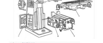
Before you start working with industrial equipment, you need to study the design of milling units. It consists of several elements:
- Bed. Cast base that dampens vibrations of a running engine. The remaining elements of the router are fixed to the bed. Compact machines are equipped with wheels for easy movement around the workshop.
- Desktop. Equipped with a workpiece clamping system to change the angle of inclination of the working surface.
- Guides. The work table moves along them while working with a part.
- Spindle. The main element of equipment that transfers rotational energy to the cutter. Located at the top of the machine.
- Console. The second name is load-bearing beam. It holds the desktop and guides.
- Gear box.
Milling machines can be equipped with a console or sold without it. Improved models are equipped with a CNC system, which increases the efficiency of the production process.
Machine care
Only someone who knows well the structure of all mechanisms and how they operate can properly service the equipment. Basic mechanisms to learn:
- drive unit;
- spindle and its bearings;
- speed and feed box;
- table;
- dividing head;
- accessories and devices.
One of the main conditions that guarantees proper maintenance of equipment is proper timely lubrication and cleanliness of the workplace.
All mechanisms must be adjusted for smooth operation, which means that they must work without stopping or play. Overloading should not be allowed, as this will affect the operation of the machine. The result of the work is influenced by the fastening of the cutter and the workpiece. Rotating the cutter in the opposite direction is unacceptable. Its teeth will crumble and it will become unusable.
Do not place foreign objects on the machine table. The chips that form on the table must be removed frequently, as they not only interfere with observing the work of the cutter, but also fill the gaps between the teeth, increasing friction and energy consumption.
It is necessary to ensure that the waste liquid is drained into the reservoir, since if the liquid spills chaotically, it can mix with the oil and reduce the quality of the lubricant. After use, the equipment must be wiped with a dry cloth.
Do not leave machinery unattended during operation.
Characteristics
When choosing equipment, it is important to understand the characteristics of vertical milling machines. Particular attention must be paid to the following parameters:
- Dimensions of equipment, weight. The choice depends on the size of the room, the base, and the required stability of the machine.
- Desktop size. When choosing equipment, you need to take into account the dimensions of the workpieces that will be processed most often.
- The movement of the working surface along the guides.
- Availability of spindle speed switching.
- Electric motor power.
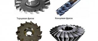
If parts made of alloy, high-carbon steels are processed, you need to choose powerful milling cutters. Equipment (cutters) is selected depending on the technological operation being performed.
Specifications
- The height of the spindle above the table surface is from 30 to 500 mm;
- Maximum table movement: in the vertical plane - 430 mm; in the longitudinal - 1000 mm; in the transverse - 400 mm.
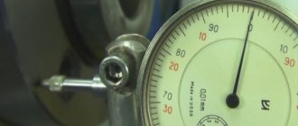
- The amount of table movement per dial division is 0.05 mm in any plane.
- The table's idle speed is up to 4000 mm/min in the horizontal plane and up to 1330 mm/min in the vertical plane.
- The feed rate is up to 12.5-1600 mm/min in the horizontal plane and up to 4.1-530 mm/min in the vertical plane.
- The maximum cutter diameter for roughing is 200 mm.
- There are 18 spindle speeds in total.
- Spindle rotation speed - from 31.5 to 1600 rpm.
- The maximum rotation angle of the spindle head is 45 degrees.
- The drive power of the main movement is 11 kW.
- Feed drive power - 3 kW.
- The maximum weight of the workpiece or part being processed is 630 kg.
- Overall dimensions of the machine: height - 2430 mm; length - 2570 mm; width - 2250 mm.
- The weight of the equipped machine is 4300 kg.
Application area
Using milling machines, you can perform various technological operations. This makes the equipment universal and indispensable in production. Used for many technological processes:
- Production of complex shaped products from metals and alloys.
- Mechanical engineering.
- Manufacturing of parts for industrial machines and electrical appliances.
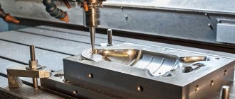
Manufacturing of parts
Technical capabilities
Speaking about classic models of vertical milling machines, without additional functions or non-standard components, they are designed to perform the following technological operations:
- boring;
- milling;
- end processing;
- selection of grooves;
- cutting off the metal layer;
- drilling
Before carrying out work, you need to check the availability of cutters. Depending on the equipment used, the type of processing changes. Technical capabilities depend on the power of the electric motor, the size of the desktop, the ability to change its position, and the control system.
Manufacturers
You can find many models of vertical milling machines on the world market. They differ in design, power, additional functions, and appearance. Among the most popular companies are:
- Jet. The products are represented in several lines. Among them there are professional and simple models. Some buyers complain about the unstable base, which they have to weigh down themselves.
- Anchor Corvette. Budget routers for beginners. Suitable for roughing metal workpieces. However, for more accurate and efficient work, you need to choose professional equipment.
- Proma. Another well-known company. The company has gained popularity thanks to the manufacture of powerful, productive machines that are used in enterprises, car services, and private workshops.
Industrial equipment for serial production of parts is ordered from factories.
Safety precautions when working
Since the vertical milling machine itself works slowly, injuries most often occur due to fingers getting caught under the teeth of the cutter. Therefore, it is strictly forbidden to remove chips by hand; cleaning the cutter teeth must be done with a special brush.
The cause of the accident may be chips getting into the eye. To avoid this, be sure to wear safety glasses when working.
Special clothing should not be too durable and should fit tightly to the body. Because the ends of dangling clothing can get caught in rotating machinery and cause injury.
Injury may result from careless handling of workpieces. Heavy parts falling can cause injury to legs or arms.
Malfunction of electrical devices and careless handling of them can lead to electric shock.
To eliminate the possibility of falling when moving on a slippery floor, you need to work in special shoes.
The milling process allows you to produce parts of various shapes and sizes. The most common version of a metal milling machine is the version where the spindle is located vertically. Such equipment began to be called vertical milling machines.
Cantilever vertical milling machines are made on the basis of horizontal milling machines with slight modifications to the gearbox and frame.
The stage of development of machine tools before the advent of CNC
All machines can be divided into two groups:
- A group in which setting operating modes, feeding and other actions are carried out by a person.
- A group of metal processing machines, the operation of which is fully or partially automated using a numerically controlled unit.
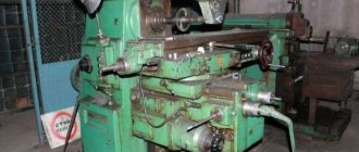
Vertical spindle milling machines without CNC have been used for several decades. The following models have become the most popular: 6Т12, 6М12П, 6Р12, 6Р12Б. These representatives of the group of milling machines were very common in the former USSR. Only after the superiority of CNC from an economic point of view and other characteristics was proven by calculations and in practice, these metal machines began to be replaced with new ones. However, 6P12 can be found in almost all large machine-building plants.
If we briefly describe the characteristics of this equipment, we can highlight the following features:
- They process almost all metals and alloys, including cast iron. According to this indicator, the limitation is the resistance of the cutting tool used to abrasion and destruction when processed under the specified operating modes of a certain type of material.
- similar design: the presence of a milling head, table, slide, spindle, bed.
- reliability and unpretentiousness are qualities that determined the popularity of the above machines. At the time of production, these machines were exported to many countries around the world.
- With the help of them you can carry out milling, drilling, boring. In addition, we note the appearance of a mechanism for rotating the head at an angle of 45° relative to the table. This feature made it possible to create elements that are located relative to the base plane at a certain angle.
User manual
When a vertical milling machine is selected, purchased and delivered to the site of operation, it must be prepared for further use. Sequencing:
- Unpack the car. Clean its surface from the protective composition applied at the factory.
- Place the router indoors and check its stability. He should not stagger or move with minor movements.
- Check fasteners. Install protective shields and ensure high-quality lighting of the working surface.
- Assemble the individual components together.
- Install the cutter.
- Adjust the work table and secure the workpiece.
Connect the router to the network, check the settings. If the router is equipped with a CNC system, you need to remove the established tasks and set your own algorithm.
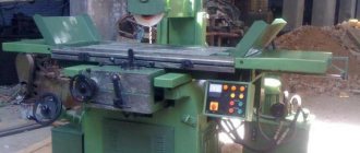
Installation of vertical milling machine
Router maintenance
In addition to preparing for operation of the router, we must not forget about maintenance. This includes the following actions:
- Blowing the moving mechanisms of the machine using a compressor.
- Lubrication of gears, guides, bearings with engine oil.
- Cleaning equipment after work processes from the accumulation of metal shavings.
- If there is no coolant supply system, the milling cutter needs rest when processing hard alloys and metals.
- Checking the tension of the belts in the gearbox.
If equipment parts fail, they must be replaced immediately.
Repair
When the machine is actively used or performed incorrectly, breakdowns occur:
- Engine overheating, accompanied by unpleasant noises. The problem is the failure of the electrical circuit, the combustion of the winding. To correct problems, you need to contact a repair shop.
- Bearings on vertical milling machines often start to knock. More often this is due to a small amount of lubricating mixture. They need to be treated with engine oil.
- The teeth on the gears wear out. They need to be periodically replaced with new ones.
Vertical milling machines are used in various industries. With their help, workpieces of complex shapes are made, holes are drilled, bored, ends are machined, and grooves are selected.
About milling machines in general
Design of milling machines with a lower spindle
A single spindle milling machine with manual feed and a lower spindle (Fig. 1) consists of a frame along which the support moves vertically. The spindle is mounted in a support on ball bearings. For a long attachment, a bracket with a folding bearing is provided to ensure spindle stability. When changing tools, the bracket is moved to the Y side. Guide rulers and clamps are installed in the table slots. The height of the spindle is adjusted using a handwheel.
The electric motor is connected to the spindle by a flat belt transmission. The pulley mounted on the spindle has an elongated shape, which allows you to change the position of the spindle in height without changing the position of the electric motor.
Rice. 1. Single-spindle milling machine F-4: 1 - bed, g - support, 3 - spindle lifting handwheel, 4 - table, 5 - removable guide rulers, 6 - bracket with folding bearing, 7 - receiving funnel, 8 - handwheel for tension belt
The FSA machine for linear milling has a more advanced design (Fig. 2). Just like the F-4 machine, its spindle is mounted on a support. The height position of the spindle is changed using the handwheel. The spindle is connected to the electric motor shaft by a belt drive; a handwheel is used to tension the belts. An automatic feeder is installed above the machine table. Its feed rollers are hinged, which allows you to feed workpieces with a difference in thickness of up to 20 mm into the machine. If manual feeding is required, the automatic feeder can be removed from the machine or moved to the side (for example, when installing a cutting tool). To change the position of the automatic feeder in the vertical plane, a flywheel is provided. The flywheel connected to the variator sets the feed speed, which can vary within 8-25 mm.
Convenient placement of the control panel allows the machine operator not to make unnecessary movements during operation.
In Fig. Figure 3 shows a kinematic diagram of the FA-4 milling machine with automatic feed. A block of sprockets is mounted movably on the spindle, in ball bearings, and rotates independently of the spindle. The workpiece to be processed is placed in a tsulaga and secured in it. Part of the side surface of the tsulagi acts as a copier; a bushing-roller chain or perforated tape corresponding to the teeth of the upper sprocket of the block is fixed to it. During operation of the machine, the upper sprocket engages with the chain and feeds the tulaga with the material being processed along the cutting tool. The upper sprocket is driven by the lower (drive) sprocket of the block, which is connected by a chain transmission to the feed mechanism drive, which includes an electric motor, a worm gearbox and a gear drive.
The design of the feed mechanism provides the ability to impart a rectilinear movement to the template when processing workpieces on one side and rotational movement when processing along a contour. Parts with a contour outlined in a circle are processed with a moving axis of rotation of the template. In all other cases, the contour points of curved parts are at different distances from the cutting circle described by the cutter. Therefore, in order to ensure continuous contact of the workpiece with the cutting tool, it is necessary to change the distance from the center of rotation of the template to the cutting circle. To do this, insert 6 with a finger is movably secured and a lever is installed that connects the template with the spring. When installing and removing the template, the insert with the finger is moved away from the spindle axis with a pedal. If one side of a curved workpiece is processed, the template is pressed against the feed sprocket by pressure rollers mounted on the liner.
Rice. 2. FSA milling machine: 1 - table, 2 - automatic feeder, 3 - handwheel for setting the feed speed, 4 - handwheel for the automatic feeder height adjustment mechanism, 5 - control panel, 6 - handwheel for the spindle height adjustment mechanism, 7 - tension mechanism handwheel belts, 8 - bed
The domestic industry also produces FSh-4 milling machines, designed not only for flat and profile milling, but also for cutting tenons. These machines are equipped with a tenoning carriage, which is movably mounted on special bed guides. Clamps, a stop ruler and end stops are installed on the carriage. Move the carriage manually. Manual movement of the carriage when modernizing the machine can be mechanized, for example, using a pneumatic cylinder with a hydraulic regulator. The clamps can be equipped with an air motor.
Rice. 3. Kinematic diagram of a single-spindle milling machine FA-4 with automatic feed: 1 - pedal, 2 - spindle support, 3 - handwheel, 4 - cable, 5 - lever, 6 - liner, 7 - pin, 8 - spring, 9 - cutter , 10 — sprocket block, 11 — gear transmission, 12 — worm gear, 13 — feed motor, 14 — spindle motor, 15 — belt tension handwheel
Operating mode selection
The choice of operating mode on milling machines of any design comes down to determining the feed rate of the workpieces being processed. Milling is often the final operation in machining workpieces, since grinding after milling (especially shaped workpieces) is difficult. Therefore, when choosing operating modes of milling machines, they proceed from the requirements for the roughness of the machined surface. The required surface roughness class depends on the feed rate and the angle at which the cutter meets the wood fibers.
Example. It is required to determine the feed rate when milling a curved part with a variable meeting angle of the fvx, which varies from 0 to 30°. The roughness of the treated surface must correspond to the seventh class. The diameter of the cutter is 120 mm, the number of cutters g = 4, the spindle makes 6000 revolutions per minute.
Setting up machines
When milling flat surfaces, the cutting edges of the lower end of the cutter should be located 3-5 mm below the table level, which is achieved by corresponding movement of the spindle. In the case of profile milling, the position of the cutter is determined by a template or sample of the part installed on the machine table.
Rice. 4. Milling machine ruler guides: 1 - rear ruler, 2 - bracket, 3 - front ruler
Through flat and profile milling of straight workpieces is performed along the rear and front guide rulers (Fig. 4), which are connected by a cast bracket covering the cutting tool. Ruler 1 can be manufactured as one piece with a bracket; the ruler is movably fixed to the bracket. Typically, rulers made of wood are applied to the metal planes of the rulers. The vertical planes of the rulers must be perpendicular to the plane of the machine table.
When flat milling, the back ruler is set along the block, when profile milling - using a standard. To do this, the block or standard is pressed against the back ruler and the spindle is manually turned in the direction opposite to the cutting direction. The cutting edges of the cutter should lightly touch the block or standard.
The front ruler should be parallel to the back one and be spaced from it when milling planes by an amount equal to the thickness of the wood layer being removed (1.5-2 mm). In the case of profile milling, the distance between the rulers should also be 1.5-2 mm, but the cutter must be extended relative to the ruler to the depth of the profile. The front ruler is installed according to the standard bar: it is pressed against the rear ruler, and the front ruler is fixed at the required distance.
If, during longitudinal milling, the edges of the workpiece are not processed along the entire length, then both rulers are installed in the same vertical plane. When non-through milling of straight workpieces, stops are installed on the machine table that limit the length of milling (workpiece movement), and the rulers are installed in the same plane.
Milling of curved surfaces is carried out using special copying rulers fixed on the cutting boards.
Setting up the machine begins with selecting a ring that is attached to the bottom or top of the cutter, depending on the design of the tsulagi. The difference in the diameter of the ring and the diameter of the cylindrical cutting surface of the cutter determines the relative position of the forming edge of the copy ruler and the machined surface of the workpiece. Therefore, for a given device, the magnitude of this difference must be strictly defined.
Working on machines
On FSSH-1A milling machines with a lower spindle, various types of processing are performed. The textbook describes the following basic operations: through milling; processing of workpieces and assemblies along the outer contour; cutting of spikes and lugs; non-through milling.
Through milling. Through milling of straight workpieces is carried out using manual feeding. The machine operator takes the next workpiece, lays it flat on the table and, pressing the edge against the guide ruler, slides it onto the cutter. It is necessary to ensure that your hand does not touch the workpiece in the processing area.
The work of the machine operator is greatly facilitated and becomes safe if the machine is equipped with a clamp of at least the simplest design in the form of a spring plate or a wooden comb - a board with non-through cuts 150-200 mm long along the fibers, made at a distance of 10-15 mm from one another. In this case, the machine operator feeds the workpiece to the cutter without pressing it against the ruler.
If, during milling, unprocessed protruding elements of the part are noticed, then it is necessary to move the front ruler towards the spindle axis. If moss appears on the treated surface, it is necessary to sharpen or change the cutting tool.
The vertical displacement of the profile is a consequence of the incorrect position of the cutter relative to the plane of the work table. The situation is corrected by moving the spindle.
An incorrect angle between the machined surfaces is the result of inaccurate installation of the rulers, especially the back ones, along which the workpiece is mainly aligned.
If the ruler is not perpendicular to the plane of the table, the treated surface may be winged; The cause of winging is often warping of the base surface.
Rice. 155. Devices for through milling: a - with a clamp, b - without a clamp; 1 - body, 2 - stop, 3 - cushion, 4 - clamp, 5 - cutter, 6 - ring, 7 - workpiece, 8 - forming edge of the template, 9 - bearing, 10 - guard, 11 - cover, 12 - spindle on the machined surface is due to the fact that the workpiece is not tightly pressed against the guide ruler or not all cutter teeth are involved in milling (this often happens when using cutters with insert teeth). If waviness appears, you should check the serviceability of the clamping devices and the sharpness of the cutter teeth. Failure to groove occurs due to the non-straightness of the milled edges or the discrepancy between the distance between the front and rear guide lines as specified. For through milling of workpieces with a curved profile of one edge, a special device is used. On the edge of the body there is a profile part (rail), which serves as a template. In Fig. 5, b shows the design of the clampless device. A freely rotating ring 6 (usually a ball bearing) is concentrically fixed to the machine spindle, serving as a stop for the template. The radius of the ring must correspond to the size of the template. The distance from the base surface of the template to the spindle axis for a given device and a certain cutter diameter is a constant value. When processing curved profile surfaces, the position of the cutter relative to the table plane is determined directly from the template with the reference part attached to it. The cutter is installed by moving the spindle in a vertical plane.
Rice. 6. Scheme of milling on a machine with mechanized feed: a - workpiece with one curved edge, b - workpiece with two curved edges; 1 - device (template), 2 - stop, 3 - feed pressure rollers, 4 - clamp, 5 - workpiece, 6 - driven bush-roller chain on the template, 7 - feed drive sprocket, 8 - clamps, 9 - cutter, 10 - support ring, 11 - end stop
Before milling, blanks for curved parts (especially with large curvature) must be pre-processed on a band saw with an allowance for milling. An indispensable condition for obtaining an accurate profile is a tight fit of the workpiece to the base surfaces of the fixture and the stop.
Having secured the workpiece in the device, it is pressed with a template edge to the ring and moved along the table, processing the side surface of the workpiece. If unmilled areas remain, this indicates a small allowance or an incorrect selection of the ring diameter.
If the milling machine has a feed mechanism in the form of an asterisk on the spindle, then a bushing roller chain is secured to the figured edge of the device (Fig. 6, a). In this case, the machine operator places the workpiece in the fixture, slides it onto the cutting tool and uses a pedal to retract the pressure rollers. After the feed mechanism sprocket engages with the chain, it releases the pedal, the rollers press the device against the sprocket and it automatically moves during the entire milling process of the part. At the end of the operation, the machine operator retracts the rollers, returns the device to its original position and removes the processed workpiece.
Workpieces with two curved edges are milled, placing them two in one fixture (Fig. 6, b). The machine operator feeds the device first with one side, then returns it to its original position and feeds it onto the cutting tool with the other side. After this, the part processed on both sides is removed, a workpiece is placed in its place on the other side of the template, and another unprocessed workpiece is placed in its place. This method saves time on auxiliary operations.
Processing along the contour. Processing panels and assemblies along the outer contour is not fundamentally different from milling curved workpieces, since devices and thrust rings are also used.
The shield is placed on the machine table and a template device with spikes is placed on top of it. The spindle thrust ring is located above the cutter. The device is brought together with a shield pinned onto its spikes to the spindle and passed along the contour, and the template at this time is pressed against the shield, and the edge against the thrust ring.
A device for milling nodes along a contour (Fig. 7, a) consists of a template with a perforated tape or a bushing-roller chain. The knot is pinned onto the template, and the template, which has a hole in the center, is installed on the liner finger. To do this, the machine operator, pressing the pedal, moves his finger away from the spindle and puts the device with the unit being processed onto the finger. Then the machine operator releases the pedal, the chain of the device is pressed against the sprocket and engages with it. The feed mechanism sprocket rotates the device with the workpiece being processed around the finger, which presses the template against the ring using a spring. When the device makes a full revolution, the machine operator presses the pedal, moves the template away from the spindle and removes the processed assembly from it.
Cutting studs and removing lugs. Milling machines with a carriage are used for cutting tenons and selecting lugs. Precisely trimmed workpieces are placed on a tenoning carriage (Fig. 7, b) close to the ruler, secured with a clamp and fed together with the carriage to the end milling cutter or to the lug disk. To avoid chipping, a previously processed part is placed on the carriage behind the workpieces.
Rice. 7. Processing on milling machines: a - nodes along the contour, b - sampling of tenons; 1 - template, 2 - pressure roller, 3 - liner, 4 - workpiece, 5 - clamp. 6. 8, 13 — brackets, 7, 10 — cutters, 9 — sprocket. 11 — cutter guard, 12 — ruler, 14 — carriage
After cutting the tenons at one end, the workpiece (or workpieces when fed in a pack) is turned 180° and fed to the cutting tool with the second end. The accuracy of the length of the tenon depends on the accuracy of the trim. It is better to process the second end of the workpiece, basing it on the shoulders of the tenons of the already processed end.
The distance between the shoulders or vertical walls of the studs should be checked. If it differs from that specified in the drawing, then this indicates that the stop was installed incorrectly or that the workpieces were not accurately trimmed or had different lengths.
Non-through milling.
The scheme of non-through milling along stops is shown in Fig. 8. The workpiece is placed on the machine table, pressed against the stop and slowly pushed onto the cutter until its edge presses the workpiece against the ruler. After this, based on the table and ruler, the workpiece is moved all the way and moved away from the cutting tool.
On milling machines it is strictly prohibited: to use single-cut knife heads and clamping washers with flanges; process parts with a cross-section smaller than 5 x 5 cm without a pusher; mill workpieces along a curved profile against the direction of the grain.
Video of the operation of a used FSSH-1A milling machine after repair at NEVASTANKOMASH LLC
Video of the operation of a used FSh-1 milling machine after repair at NEVASTANKOMASH LLC