Specialties related to construction, architecture, mechanical engineering, design and others require students to be able to make drawings, read them and use special symbols. Undoubtedly, a lot depends on the specialization and the object that needs to be presented. Agree, there is a significant difference between the master plan of a site for the production of ceramic tiles and a complex section of a crankshaft. Collectively, the designations in the drawings include:
- Letters , which reflect conventional quantities, such as center distance, width, perimeter, diameter, height, depth, spring coil pitch and much more. To indicate massive and extensive sizes, it is recommended to use capital letters.
- Digital , which indicate exact dimensions, angular deviations, and the like.
- Alphanumeric , mainly found in drawings of electrical installations and have a positional designation
- Graphic, which can be used to designate anything: both the material of the product (abrasive, iron, wood) and structural elements (window, door, staircase).
Where can I find a list of symbols?
You will find designations in a variety of reference materials and books, design regulations and guidelines for the specialization you need. To find more accurate and correct designations, we recommend using GOSTs:
| GOST number | Name |
| GOST 2.303-1968 | Unified system of design documentation. Lines |
| GOST 2.306-1968 | Unified system of design documentation. Designations of graphic materials and rules for their application in drawings |
| GOST 2.315-1968 | Unified system of design documentation. Simplified and conventional images of fasteners |
| GOST 21.112-1987 | System of design documents for construction. Lifting and transport equipment. Legend |
| GOST 21.204-1993 | System of design documents for construction. Conventional graphic symbols and images of elements of master plans and transport structures |
| GOST 21.205-1993 | System of design documents for construction. Symbols for elements of sanitary systems |
| GOST 21.206-1993 | System of design documents for construction. Pipeline symbols |
| GOST 21.302-1996 | System of design documents for construction. Conventional graphic symbols in documentation for engineering-geological surveys |
| GOST 21.501-2011 | System of design documents for construction. Rules for the execution of working documentation of architectural and structural solutions |
Thanks to drawing, this universal language of engineers, knowledge and unique achievements in many specializations have become the property of all mankind, accelerating the path to perfection.
Are you confused about the symbols on the drawings? There is a proven option for the teacher to like the work - order a drawing from our experts!
Introduction
1. The shape and main dimensions of the corrugations must correspond to those shown in the drawing.
3. Steps of corrugations, mm, should be selected from the rows:
straight – 0.5; 0.6; 0.8; 1.0; 1.2; 1.6;
mesh – 0.5; 0.6; 0.8; 1.0; 1.2; 1.6; 2.0.
An example of a symbol for straight corrugation with a pitch of =1.0 mm.
Corrugation straight 1.0 GOST 21474-75
Corrugation mesh 1.0 GOST 21474-75
4. The height, angle and dependence of the corrugation pitch on the diameter and width of the rolling surface are given in the recommended application.
Indication of product markings on the drawings
Requirements for marking and branding are placed in the technical requirements of the drawing and are designated by the terms: “Mark ...” or “Mark ...”.
Requirements for stamping are placed on the drawings when there is a need to take into account the specific location of the stamp on the part, the dimensions and method of marking the stamp.
The marking or branding location on the product image is marked with a dot, and then connected by a leader line with the marking or branding signs. These signs are installed outside the image.
Is it difficult to figure it out on your own?
Try asking your teachers for help
Solving problems Tests Essays
The marking mark is marked with a circle with a diameter of ten to fifteen millimeters, and the branding sign is marked with an equilateral triangle with a height of ten to fifteen millimeters.
Designation of materials in drawings
The drawings contain graphic designations of materials that will be used in the production of the part. When defining material types, the following lines are used:
- Solid.
- Dotted.
- Inclined.
- Line.
- Dot-dash.
- Intermittent and others.
The graphic designation of materials in sections depending on the type of materials is as follows:
- Metals and hard alloys – inclined solid line.
- Wood is a curved solid line.
- Natural stone - inclined dashed line.
- Ceramics and silicate materials for masonry - double continuous inclined line.
- Concrete – Dash-dotted, slanted line.
- Liquids – dashed horizontal lines.
For welding seams, the following are used: a) a solid line for the outer part of the seam; b) dotted line for the inside of the seam. To designate the welds themselves, a broken line is used, consisting of a horizontal and inclined section, ending with a one-sided arrow, which indicates the location of the weld.
ANNEX 1
STATE STANDARD OF THE USSR UNION
UNIFIED SYSTEM OF TECHNOLOGICAL DOCUMENTATION
SUPPORTS , CLAMPS AND INSTALLATION DEVICES. GRAPHICAL SYMBOLS
GOST 3.1107-81
( CT SEV 1803 -79)
STATE STANDARD OF THE UNION OF THE SSR
| Unified system of technological documentation SUPPORTS , CLAMPS AND INSTALLATION DEVICES. GRAPHICAL NOTATION Unified system for technological documentation. Bases, clamps and installing arrangements. Symbolic representation | GOST 3.1107-81 ( CT |
By Decree of the USSR State Shock Committee on Standards dated December 31, 1981 No. 5943, the introduction date was established
from 01.07.82
1. This standard establishes graphic designations of supports, clamps and installation devices used in technological documentation.
The standard fully complies with ST SEV 1803-79.
2. To depict the designation of supports, clamps and installation devices, a solid thin line should be used in accordance with GOST 2.303-68.
3. Designations of supports (conditional) are given in table. .
Table 1
| Name of support | Support symbol in views | ||
| front, back | above | from below | |
| 1. Fixed | |||
| 2. Movable | |||
| 3. Floating | |||
| 4.Adjustable | |||
4. It is allowed to depict the designation of movable, floating and adjustable supports in top and bottom views as the designation of a fixed support in similar views.
5. Designations of terminals are given in table. .
6. The designation of a double clamp on the front or rear view, when the points of application of force coincide, can be depicted as the designation of a single clamp on similar views.
7. Designations of installation devices are given in table. .
table 2
| Clamp name | Clamp designation in views | ||
| front, back | above | from below | |
| 1. Single | |||
| 2. Double | |||
Note. For double clamps, the length of the arm is set by the designer depending on the distance between the points of application of forces. A simplified graphic designation of a double clamp is allowed: .
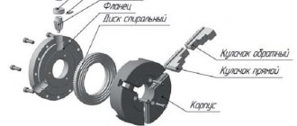
8. Installation and clamping devices should be designated as a combination of designations for installation devices and clamps (reference appendix).
Note. For collet mandrels (cartridges), the designation should be used - .
9. It is allowed to mark supports and installation devices, except for centers, on extension lines and corresponding surfaces (reference appendices and).
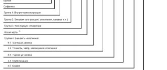
10. To indicate the shape of the working surface of supports, clamps and installation devices, designations should be used in accordance with table. .
11. The designation of the shapes of the working surfaces is applied to the left of the designation of the support, clamp or installation device (reference appendices and).
12. To indicate the relief of the working surfaces (grooved, threaded, splined, etc.) of supports, clamps and installation devices, the designation should be used in accordance with the drawing.
Table 3
| Installation device name | Designation of the installation device in views | ||
| front, back, top bottom | left | on right | |
| 1. The center is stationary | Without designation | Without designation | |
| 2. Center rotating | Same | Same | |
| 3. Center floating | » | » | |
| 4. Cylindrical mandrel | |||
| 5. Ball mandrel (roller) | |||
| 6. Drive chuck | |||
Notes:
1. The designation of reverse centers should be done in a mirror image.
2. For basic mounting surfaces, it is allowed to use the designation - .
Table 4
| Name of working surface shape | Designation of the shape of the working surface in all views |
| 1. Flat | |
| 2. Spherical | |
| 3. Cylindrical (ball) | |
| 4. Prismatic | |
| 5. Conical | |
| 6. Rhombic | |
| 7. Triangular |
Note. The indication of other forms of the working surface of supports, clamps and installation devices should be carried out in accordance with the requirements established by industry normative and technical documentation.
13. The designation of the relief of the working surface is applied to the designation of the corresponding clamp support or installation device (reference appendix).
14. To indicate clamping devices, designations should be used in accordance with table. .
Table 5
| Clamping device name | Designation of the clamping device on all types |
| 1. Pneumatic | R |
| 2. Hydraulic | N |
| 3. Electric | E |
| 4. Magnetic | M |
| 5. Electromagnetic | EAT |
| 6. Other | Without designation |
15. The designation of the types of clamping devices is applied to the left of the designation of the clamps (reference applications and).
Note. For hydroplastic mandrels it is allowed to use the designation - .
16. The number of points of application of the clamping force to the product, if necessary, should be written to the right of the clamp designation (reference appendix, item 3).
17. On diagrams that have several projections, it is allowed on separate projections not to indicate the designations of supports, clamps and installation devices relative to the product, if their position is clearly determined in one projection (reference appendix, item 2).
18. On the diagrams, it is allowed to replace several designations of supports of the same name in each view with one, indicating their number (reference appendix, item 2).
19. Deviations from the dimensions of the graphic symbols indicated in the table are allowed. - and on the drawing.
Information
| Name | Examples of marking supports, clamps and installation devices |
| 1. Fixed center (smooth) | |
| 2. Center grooved | |
| 3. Center floating | |
| 4. Center rotating | |
| 5. Reverse rotating center with grooved surface | |
| 6. Drive chuck | |
| 7. Movable rest | |
| 8. Fixed lunette | |
| 9. Cylindrical mandrel | |
| 10. Conical mandrel, roller | |
| 11. Threaded mandrel, cylindrical with external thread | |
| 12. Splined mandrel | |
| 13. Collet mandrel | |
| 14. Adjustable support with spherical convex working surface | |
| 15. Pneumatic clamp with a cylindrical corrugated working surface |
Information
| Description of installation method | Designation scheme |
| 1. In a vice with prismatic jaws and pneumatic clamping | |
| 2. In a jig with centering on a cylindrical pin, with emphasis on three fixed supports and using an electric double clamping device having spherical working surfaces | |
| 3. In a three-jaw chuck with a mechanical clamping device, with an end stop, with a rotating center and with fastening in a movable rest | |
| 4. On a conical mandrel with a hydroplastic clamping device, with an end emphasis on a corrugated surface and with pressure from a rotating center |
9.5. Making a drawing of a part that has the shape of a body of revolution
Parts that have the shape of a body of rotation are found in the vast majority (50-55% of the original parts) in mechanical engineering, because rotational movement is the most common type of movement of elements of existing mechanisms. In addition, such parts are technologically advanced. These include shafts, bushings, disks, etc. processing of such parts is carried out on lathes, where the axis of rotation is located horizontally.
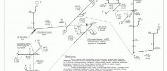
Therefore, parts having the shape of a body of rotation are placed on the drawings so that the axis of rotation is parallel to the main inscription of the drawing (stamp). It is advisable to place the end of the part, taken as the technological base for processing, on the right, i.e. the way it will be positioned during processing on the machine. The working drawing of the bushing (Figure 9.9) shows the execution of a part that is a surface of rotation. The outer and inner surfaces of the part are limited by surfaces of rotation and planes. Another example could be the “Shaft” part (Figure 9.10), limited by coaxial surfaces of rotation. The center line is parallel to the title block. Dimensions are given in a combined way.
Figure 9.9 - Working drawing of a part of the surface of rotation
Figure 9.10 — Working drawing of the “Shaft” part
Designations in mechanical engineering
Definition 1
Mechanical engineering is a complex, cost-intensive procedure for the manufacture of equipment and spare parts for it.
The procedure for producing equipment must be preceded by a planning procedure, which consists of creating material and technical projects and drawing drawings, diagrams and diagrams.
Definition 2
Product drawings involve graphic images of a part or part thereof. Drawings are made to a designated scale, indicating the required standard sizes and technical conditions that are used to create the drawn part or part thereof.
All drawings must be carried out in accordance with accepted GOST standards. It is mandatory that the drawings indicate dimensions with possible, maximum discrepancies from the actual size.
Limit discrepancies must be indicated in digital form (16+0.027 or 135±0.1), and, if necessary, with relative abbreviations (letters of the Latin alphabet).
Tolerances of shape and location of surfaces are indicated by relative definitions, which are established by GOSTs and are placed in a rectangular frame, divided into three parts. In the first part of the frame there is a sign of the type of tolerance.
The second part of the frame contains the numerical value of the tolerance, and is usually reflected in millimeters. The third frame displays a letter marking the surface to which the specified tolerances apply. Technological documents, in addition to drawings, include sketches. These sketches indicate the conditional positioning of installations and fastening of parts on racks. The specified conditions must be fulfilled accurately in order to accurately manufacture products within the limits of possible discrepancies.
Requirements for the execution of sketches:
- The sketch shows the part in the location in which it will be produced.
- The surface to be treated must be marked with lines, the thickness of which should be more than 2 times greater than the thickness of other lines.
- The sketch marks those exteriors that are processed in a particular process.
- The surfaces to be processed contain the roughness, tolerances and dimensions marked on the sketch. They must be produced during processing.
- The direction of movement of processing tools and workpieces is indicated by arrows.
Did not you find what you were looking for?
Just write and we will help
During the production of drawings, several types of lines are used: solid, dotted, dash-dotted and wavy.
Inscriptions on drawings
It is recommended to make inscriptions on drawings only when it is not advisable to show information about the product in numerical or alphabetic expressions. Even when comments or detailing of the drawing are required.
At the same time, the content of the inscriptions must be very brief and precise. The inscriptions on the drawings should not contain abbreviations of words, with the exception of generally accepted ones, as well as those established in the standards and specified in the appendix to this standard.
The placement of inscriptions must be done exclusively on the shelves of the leader line. And the information on the callouts should only apply to a specific image.
A leader line that intersects the outline of the image and does not depart from any line is completed with a dot. The leader line, drawn from the lines of the external and internal contours, as well as from the lines that indicate the surface, ends with an arrow.
At the end of the leader line, drawn from all other lines, there should be no arrows or dots. Leader lines should not intersect each other, should not run parallel to hatch lines (if the leader line passes through a shaded area of the drawing) and, if possible, dimension lines and drawing elements should not intersect.