How to connect mechanism shafts?
To transmit axial rotation, shafts are used, on which various gears and sprockets can be mounted. The connection is carried out using various methods, for example, couplings are used to connect shafts. Their features include the following points:
- It is possible to dismantle.
- The collection and production of the final product is greatly simplified.
- Many types of products allow you to compensate for various types of displacements that may occur during operation of the device.
- The device can withstand significant load.
Today, parts are connected to each other using welding technology extremely rarely. This is due to the fact that vibration and other impacts can cause cracks and other defects.
Incorrect fixation may result in device failure. The product is selected depending on the operating conditions. For example, shafts can move in a variety of directions.
Pump couplings
To ensure operation, the ends of the motor and pump shafts must be securely connected. The element that transmits torque is called a clutch. Considering that in each specific case the equipment operates under different conditions, the selection of couplings is carried out individually.
Factors influencing the correct choice of connecting element include:
- engine power;
- rotation frequency;
- presence of vibration;
- alignment;
- the presence of a constant or changing angle between the shafts;
- the need to quickly disconnect the connection or adjust the clutch rigidity;
Depending on the type of connection between the motor and pump shafts, couplings are divided into the following categories:
- deaf;
- hard compensating;
- elastic compensating;
- managed.
Homemade coupling
To significantly reduce costs, the possibility of using a homemade design is being considered. Among the features we highlight the following points:
- To create a homemade design, you need a sprocket that can be removed from the crankshaft of an internal combustion engine.
- The transmission of rotation is carried out using a chain. Due to the use of steel in the manufacture of this product, strength increases significantly.
- The connection is made through two coupling halves. In this case, the star should be sawn in half. A cut-off part of the sprocket will be welded onto each coupling half.
- The coupling half is fastened using bolts. However, this connection method is not recommended if the load applied is significant. Fixation of detachable elements is ensured by a key when transmitting high force.
The above information indicates that such a product can be made using available materials. In this case, the resulting device is installed to transmit high torque.
ELECTROMAGNETIC CLUTCH
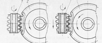
This type of coupling is an electromagnetic analogue of a hydrodynamic coupling. Electromagnetic couplings usually find the same application as hydrodynamic couplings, for example, they are installed between a marine diesel engine and a gearbox to dampen vibrations from the diesel engine. A typical electromagnetic clutch consists of two rotors. One of them is an iron disk with a thin annular protrusion at the periphery. On the inner surface of the protrusion there are radially oriented pole pieces equipped with windings through which excitation current from an external source is passed through slip rings on the shaft.
The other rotor is a cylindrical iron shaft with grooves parallel to the axis. Insulated copper bars are inserted into the grooves, connected at the ends by a ring copper collector. This rotor is free to rotate inside the first and is completely enclosed by its pole pieces.
When the excitation current is turned on and one of the rotors, say the second (which is typical for ship practice), is rotated by the engine, the magnetic field lines created by the excitation current are crossed by the conductors of this rotor (copper bars) and an electromotive force is induced in them. Since the copper bars form a closed circuit, a current created by the induced EMF flows through them, and this current generates its own magnetic field. The interaction of the rotor fields is such that the driven rotor is carried along with the leading one, albeit with a slight delay. The described principle of operation of the electromagnetic clutch is the same as that of an asynchronous electric motor with a squirrel-cage rotor.
The efficiency of an electromagnetic clutch is high, but slightly lower than that of a fluid coupling of comparable power. see also
GEAR; PASSENGER CAR; SHIP POWER PLANTS AND PROPULSIONS.
Classification of couplings
There are many different similar products that are used to transmit rotation. The classification by purpose is as follows:
- Permanent or connecting.
- Coupled and steerable.
Drive models are installed in a wide variety of designs. Neither are required for direct force transmission.
Shaft connecting products are used for constant transmission of rotation. They are divided into several main groups:
- Tough.
- Deaf.
- Connecting.
- Movable or flexible.
The simplest design option can be called blind couplings. In the manufacture of bushings and other elements, a wide variety of materials can be used, most of which are characterized by a high degree of protection from environmental influences.
Cone adapter couplings have become quite widespread, as they are easy to manufacture and can last for a long period. Splined versions can also be installed, which can transmit large forces during operation.
The classification of flexible design options is also carried out according to a large number of different characteristics. The following are widely used:
- Expansion. They are characterized by the fact that they can compensate for the axial displacement of parts relative to each other.
- Cross. Such mechanisms are installed in cases where there is a possibility of radial displacement.
- Membrane and drive, which are designed for radial and axial displacement. The leashes have a special element that ensures the position of both elements is fixed.
The selection of the most suitable connecting element is carried out according to the diametrical dimensions. The coupling halves compensate for the displacement of the axis, however, to increase the efficiency, oil is added. In most cases, steel is used in manufacturing, which is characterized by increased wear resistance. If it is necessary to protect the mechanism from the effects of electricity, special materials with certain properties are used.
Do not forget that cross products are characterized by a significant drawback - an increase in backlash due to severe wear of the protrusions.
In some cases, a leash version is used, which is also characterized by certain advantages and disadvantages.
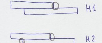
Blind couplings.
Blind couplings connect shafts without the possibility of their relative movement. Such couplings include sleeve couplings (Fig. 1), flange couplings (Fig. 2) and with an intermediate connecting element (Fig. 3).
Also on topic:
MACHINES AND MECHANISMS
Rigid shaft connection
A fairly large number of different methods of connecting shafts are used, all of them are characterized by certain qualities. The rigid connection method is used when the connection is made taking into account the absence of the likelihood of the nodes moving relative to each other at the time of operation. The classic connection method is characterized by the following features:
- In most cases, the connection is made using flanges, which are part of various mechanisms. Installation of rigid couplings is also carried out; their installation is carried out using the pressing method.
- The single-support version of the shaft has become quite widespread. In this case, the connection itself is used as a second support.
- Bolts can also be used for fixation. At the same time, they must fit tightly into the hole, otherwise serious problems may arise.
- In this case, a gear or transversely folded coupling is often used.
The transversely folded version is used for connecting various parts that are installed in electrical machines and other various units. This design consists of the following elements:
- Two coupling halves. They are mounted on the ends of shafts, which are connected into one system.
- Both parts of the structure under consideration have centering protrusions and a special recess; the connection is ensured by strong bolts.
- Safety couplings cannot be turned due to a special key hole.
- Axial displacement is eliminated due to locking screws that are screwed in at the ends.
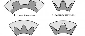
A more complex version can be called a gear coupling, which also consists of two separate parts. The outer surface consists of teeth that mesh to ensure a reliable connection. Axial displacement is eliminated through the use of bolts.
Cam - disc
Such a device is designed to transmit significant torque. They may say that they promise the same thing regarding other coupling units. This is true, but the cam-disc unit has an undeniable advantage: it does an excellent job when the assembly has to be connected/disconnected relatively rarely.
Photo: Rexnord disc clutch
This requires close matching of the shaft rotation rate. It is optionally possible to ensure their strict alignment. The sprocket is always made of a material characterized by high elasticity and elasticity. The profiles of the teeth and cams correspond to the involute.
The mechanical unit is connected manually. The force is transmitted using a system of levers. Operators only need to move the lever or twist the handle. It is connected to the required part through a worm or crank drive. This solution is technically simple and reliable, but employees will have to spend a lot of effort.
The rectangular design has a high contact-transverse area. Therefore, the transmission of very high power is facilitated. The downside is that particularly precise positioning of the coupling halves is required. Otherwise, they will engage much worse. The symmetrical trapezoid shape does not have such a requirement. Gaps in the lateral plane are eliminated by changing the seating depth of the cam.
Semi-rigid shaft connection
The semi-rigid type of connection is characterized by certain features. An example is the case of connecting a turbogenerator shaft to a steam turbine. In most cases, a semi-rigid gear-spring coupling is placed on the motor shaft.
The considered version of the connecting element is characterized by the following features:
- The design consists of two coupling halves, which are fixed on both parts. The device is installed in a similar way.
- Fixation of one element relative to another is carried out due to an elastic wave-shaped tape spring, which is often called a compensator.
To ensure the required level of protection, a casing is used, which is made from a variety of environmentally resistant materials. Minor changes in the position of the two elements being connected are compensated by a special element.
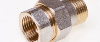
Connecting coupling for pump and electric motor OMT ND
ND claw coupling with pre-drilled holes for connecting the NS shaft High pressure gear pump
pump and shaft
AIR electric motors asynchronous alternating current
electric motor.
Consists of two coupling halves and an elastic element.
Material: aluminum.
Operating temperature range from -30°C to +80°C.
Table with markings for ND coupling halves to the electric motor and to the pump
| power, kWt | Size | Shaft diameter, mm | Marking | Marking | Group | Shaft version | |
| 0,12-0,18 | 63 | 11 | ND 48A | ND48U1PND48PZB | 1 | conical 1:8 | R-42 |
| 0,25-0,37 | 71 | 14 | ND 48B | ||||
| 0,55-0,75 | 80 | 19 | ND 48C | ZB | conical 1:5 | ||
| 80 | 19 | ND 65A | ND 65 P2 | 2 | conical 1:8 | R-62 | |
| ND 65 P ZF | ZF | conical 1:5 | |||||
| 1,1-1,5 | 90 | 24 | ND 48D | ND 48 U1P | 1 | conical 1:8 | R-42 |
| ND 48 P ZB | ZB | conical 1:5 | |||||
| 90 | 24 | ND 65B | ND 65 U1P | 1 | conical 1:8 | R-62 | |
| ND 65P ZB | ZB | conical 1:5 | |||||
| ND 65 P2 | 2 | conical 1:8 | |||||
| ND 65 P ZF | ZF | conical 1:5 | |||||
| 2,2-4 | 110-112 | 28 | ND 65C | ND 65 U1P | 1 | conical 1:8 | |
| ND 65 P2 | 2 | conical 1:8 | |||||
| ND 65P ZB | ZB | conical 1:5 | |||||
| ND 65 P ZF | ZF | conical 1:5 | |||||
| 110-112 | 28 | ND 86A | ND 86 P2 | 2 | conical 1:8 | R-82 | |
| ND 86 3U | 3 | conical 1:8 | |||||
| ND 86 P ZF | ZF | conical 1:5 | |||||
| ND 86 P ZG | ZG | conical 1:5 | |||||
| 5,5-9 | 132 | 38 | ND 86B | ND 86 U1P | 1 | conical 1:8 | |
| ND 86 P2 | 2 | conical 1:8 | |||||
| ND 86 3U | 3 | conical 1:8 | |||||
| ND 86 P ZF | ZF | conical 1:5 | |||||
| ND 86 P ZG | ZG | conical 1:5 | |||||
| 5,5-9 | 132 | 38 | ND 108A | ND 108 P2 | 2 | conical 1:8 | R-103 |
| 11-15 | 160 | 42 | ND 108B | ND 108 U1P | 1 | conical 1:8 | |
| ND 108 P2 | 2 | conical 1:8 | |||||
| ND 108 3U | 3 | conical 1:8 | |||||
| ND 108 Q4 | 4 | conical 1:8 | |||||
| ND 108 P ZF | ZF | conical 1:5 | |||||
| ND 108 P ZG | ZG | conical 1:5 | |||||
| 18,5-22 | 180 | 48 | ND 108C | ND 108 P2 | 2 | conical 1:8 | |
| ND 108 3U | 3 | conical 1:8 | |||||
| ND 108 Q4 | 4 | conical 1:8 | |||||
| ND 108 P ZF | ZF | conical 1:5 | |||||
| ND 108 P ZG | ZG | conical 1:5 | |||||
| 30 | 200 | 55 | ND 108D | ND 108 Q3U | 3 | conical 1:8 | |
| ND 108 Q4 | 4 | conical 1:8 | |||||
| ND 108 Q ZG | ZG | conical 1:5 | |||||
| 37-45 | 225 | 60 | ND 143C | ND 143 P4 | 4 | conical 1:8 | R-132 |
Alignment of OMT ND coupling halves to the electric motor and to the pump
| Marking | ||||||
| A | WITH | G | D | CH | T | |
| ND 48A | 48 | 30 | 19 | 11 | 4 | 12,8 |
| ND 48B | 48 | 30 | 29 | 14 | 5 | 16,3 |
| ND 48C | 48 | 38 | 54 | 19 | 6 | 21,8 |
| ND 48D | 48 | 38 | 54 | 24 | 8 | 27,3 |
| ND 65A | 65 | 42 | 47,5 | 19 | 6 | 21,8 |
| ND 48D | 48 | 38 | 54 | 24 | 8 | 27 |
| ND 65B | 65 | 48 | 47,5 | 24 | ||
| ND 65C | 65 | 53 | 57,5 | 28 | 8 | 31,3 |
| ND 86A | 86 | 55 | 60 | 28 | 8 | 31,3 |
| ND 86B | 86 | 73 | 88 | 38 | 10 | 41,3 |
| ND 108B | 108 | 84 | 110 | 42 | 12 | 45,3 |
| ND 108C | 108 | 100 | 110 | 48 | 14 | 51,8 |
| ND 108D | 108 | 100 | 110 | 55 | 16 | 59,3 |
| ND 143C | 143 | 137 | 140 | 60 | 18 | 64,4 |
| Marking | Group | Shaft version | ||||||
| A | B | d | CH | T | E | |||
| ND 48 U1PND 48 P ZB | 48 | 30 | 9,7 | 2,4 | 10,5 | 17 | 1 | conical 1:8 |
| 9,8 | 2 | 10,2 | ||||||
| 9,7 | 2,4 | 10,5 | ZB | conical 1:5 | ||||
| 9,8 | 2 | 10,2 | ||||||
| ND 65 P2 | 65 | 34 | 17,2 | 3,2/4 | 18,5 | 21,5 | 2 | conical 1:8 |
| ND 65 P ZF | 16,9 | 3 | 19 | ZF | conical 1:5 | |||
| ND 48 U1P | 48 | 30 | 9,7 | 2,4 | 15 | 17 | 1 | conical 1:8 |
| ND 48 P ZB | 9,8 | 2 | 12 | ZB | conical 1:5 | |||
| ND 65 U1P | 65 | 34 | 9,7 | 2,4 | 15 | 21,5 | 1 | conical 1:8 |
| ND 65P ZB | 9,8 | 2 | 12 | ZB | conical 1:5 | |||
| ND 65 P2 | 17,2 | 3,2/4 | 23 | 2 | conical 1:8 | |||
| ND 65 P ZF | 16,9 | 3 | 19 | ZF | conical 1:5 | |||
| ND 65 U1P | 65 | 34 | 9,7 | 2,4 | 10,5 | 21,5 | 1 | conical 1:8 |
| ND 65 P2 | 17,2 | 3,2/4 | 18,5 | 2 | conical 1:8 | |||
| ND 65P ZB | 9,8 | 2 | 12 | ZB | conical 1:5 | |||
| ND 65 P ZF | 16,9 | 3 | 17,7 | ZF | conical 1:5 | |||
| ND 86 P2 | 86 | 48 | 17,2 | 3,2/4 | 18,5 | 27 | 2 | conical 1:8 |
| ND 86 3U | 22,2 | 4 | 23,6 | 3 | conical 1:8 | |||
| ND 86 P ZF | 16,9 | 3 | 17,7 | ZF | conical 1:5 | |||
| ND 86 P ZG | 25,2 | 5 | 26,3 | ZG | conical 1:5 | |||
| ND 86 U1P | 86 | 48 | 9,7 | 2,4 | 10,5 | 27 | 1 | conical 1:8 |
| ND 86 P2 | 17,2 | 3,2/4 | 18,5 | 2 | conical 1:8 | |||
| ND 86 3U | 22,2 | 4 | 23,6 | 3 | conical 1:8 | |||
| ND 86 P ZF | 16,9 | 3 | 17,7 | ZF | conical 1:5 | |||
| ND 86 P ZG | 25,2 | 5 | 26,3 | ZG | conical 1:5 | |||
| ND 108 U1P | 108 | 64 | 17,2 | 3,2/4 | 18,5 | 34 | 1 | conical 1:8 |
| ND 108 P2 | 17,2 | 3,2/4 | 18,5 | 2 | conical 1:8 | |||
| ND 108 3U | 22,2 | 4 | 23,6 | 3 | conical 1:8 | |||
| ND 108 Q4 | 33,3 | 7/6,35 | 35,5 | 42 | 4 | conical 1:8 | ||
| ND 108 P ZF | 16,9 | 3 | 17,7 | 34 | ZF | conical 1:5 | ||
| ND 108 P ZG | 25,2 | 5 | 26,3 | ZG | conical 1:5 | |||
| ND 108 P2 | 108 | 64 | 17,2 | 3,2/4 | 18,5 | 34 | 2 | conical 1:8 |
| ND 108 3U | 22,2 | 4 | 23,6 | 3 | conical 1:8 | |||
| ND 108 Q4 | 33,3 | 7/6,35 | 35,5 | 42 | 4 | conical 1:8 | ||
| ND 108 P ZF | 16,9 | 3 | 17,7 | 34 | ZF | conical 1:5 | ||
| ND 108 P ZG | 25,2 | 5 | 26,3 | ZG | conical 1:5 | |||
| ND 108 Q3U | 108 | 64 | 22,2 | 4 | 23,6 | 42 | 3 | conical 1:8 |
| ND 108 Q4 | 33,3 | 7/6,35 | 35,5 | 4 | conical 1:8 | |||
| ND 108 Q ZG | 25,2 | 5 | 26,3 | ZG | conical 1:5 | |||
| ND 143 P4 | 143 | 75 | 33,3 | 7/6,35 | 35,5 | 37 | 4 | conical 1:8 |
Elastic shaft connection
At the time of operation of the device, there is a possibility of displacement of two elements relative to each other. This problem can be solved through the use of special elements. Elastic devices can be installed in a wide variety of cases, they are characterized by the following features:
- Installation is possible in case of lateral or angular displacement of the shafts at the interface.
- Bush-pin parts have become quite widespread.
The classic device is represented by two coupling halves, which are connected using special bolt pins.
Special leather washers and cuffs are placed on the surface, which are secured using rubber cuffs.
Installation of a friction clutch on a high-speed shaft
If necessary, you can install the friction clutch yourself with a small set of tools. To obtain a high-quality result, you need to follow common recommendations:
- Before starting work, you should make sure that the structure does not have significant defects. Even minor defects cause a decrease in the strength of the connection.
- Elastic couplings have become quite widespread. Their peculiarity lies in the presence of a special element, due to which displacements are compensated. At the time of installation, you need to be careful, since too much force can cause damage to the active element. This should also be taken into account when installing safety couplings.
- In most cases, fixation is carried out by pressing the mechanism. You can eliminate the possibility of the device turning by using a key.
At the time of installation, it is not recommended to use a makeshift fixation method, as this may cause damage to the structure. An example is a change in shape and the appearance of dents, cracks, a decrease in strength and many other points.
Installation of friction and ball safety clutches on a low-speed shaft
Safety devices eliminate the possibility of damage to main elements in the event of overload. In this case, the installation process is practically no different:
- Fixation is carried out using a dowel. This method is characterized by very high reliability.
- The coupling halves are fitted under tension. This eliminates the possibility of backlash and other problems.
- When fitting, do not apply much force, as a serious defect may occur.
There are special tools on sale that greatly simplify installation work.
Installation of friction clutches on the low-speed shaft of the output gearbox
Often the product is installed on a gearbox to connect it to an electric motor. This can be attributed to the fact that the gearbox may jam, which leads to overheating of the engine. A friction clutch eliminates the possibility of such a problem. Among the installation features we note:
- Do not apply impact loads as they may damage the product itself.
- To simplify the entry of the cage, lubricant can be used.
- Violation of installation rules may cause damage to the main part.
Self-installation should be carried out exclusively taking into account the recommendations, since even a minor defect causes a reduction in service life.
There are simply a huge number of different parts on sale, due to which there are no significant problems when choosing. The main criteria include the type of material used in manufacturing, as well as the diametrical size. When choosing, attention is paid to how the displacement of the connected elements can occur.
Elastic couplings.
Due to wear, misalignment or deflection of heavy shafts under their own weight, shaft misalignment is almost inevitable. To prevent shaft beating caused by misalignment, couplings with compensating devices, called elastic couplings, have been developed. Such couplings include elastic flange (Fig. 4) and elastic belt (Fig. 5) couplings.
Also on topic:
SHIP POWER PLANTS AND PROPULSIONS