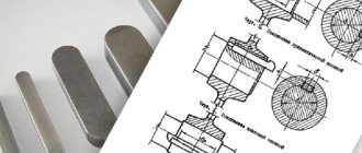
Types of keys
Modern production provides over 20 different types of items. But among them the following most used types in mechanical engineering are distinguished:
- Wedge - used on end installations and are a type of driving keys. This keyed connection is used for shaft diameters of 100 mm or more. Currently they are extremely rare. The reason for this lies in the high probability of overtightening of the unit and displacement of the alignment of the hub and shaft under the influence of one-sided force. It is also difficult to remove the keys.
- Prismatic. The groove dimensions are regulated by GOST 23360-78. They are most in demand in industry due to the optimal ratio of strength and manufacturability. There are two types of them: mortise and embedded. Mortise keys are installed with an interference fit, and embedded keys with a small gap.
- Guide keys. They are distinguished from prismatic ones by the presence of holes for fasteners on the shaft. In addition to transmitting rotation, they serve as an element for guiding parts.
- Segmental keys stand out from the rest due to their increased technology for cutting grooves. The grooves are made using disc cutters, which provides them with greater precision and productivity. The fastening of keys to shafts is also more stable due to deeper cutting into their surface. However, at the same time, all these advantages cause a significant weakening of the shaft. This circumstance, along with the short length of the groove, leads to the appearance of increased stresses, which limit the use of keys to lightly loaded products.
It is worth noting that keyways are made by milling and broaching. The most common way to produce them is with a finger cutter, since this method provides relatively favorable stress distribution and acceptable manufacturability.
DIN keys
DIN key - connecting fastener
A key is a special fastener used to connect shafts and hubs to flywheels or cylindrical wheels.
The dowel is used to fasten wooden structural elements, and it takes on shear forces.
We are ready to offer our customers different types of keys and keyed steel, you just need to indicate the dimensions of the products, and we will quickly fulfill your order.
Its operational properties depend on the standard size of each key. The use of a particular key depends on the parts being connected, as well as on the diameter of the mounting hole. On our company’s website you can find a list of fasteners we sell and their standard sizes.
A friction key is a type of wedge key. More often it is used as a safety link under significant overloads. A distinctive feature of this type of key is the ability to adjust the position of the hub not only in the angular, but also in the axial direction. This quality is often used in practice.
Wedge keys of all types belong to the group of stressed joints. The dimensions of these keys are standardized like their tolerances. Using a taper key can present some challenges.
Due to the design and shape of this key, a misalignment of the part may occur, which will lead to a malposition of the plane relative to the shaft axis (not perpendicular). To avoid this, sometimes it is necessary to individually fit the key, which is unacceptable in large-scale production conditions.
It is for this reason that large enterprises engaged in volume production are currently abandoning taper keys.
The connection with parallel keys and segment keys is called a stress-free connection. The use of segmental and parallel keys leads to the fulfillment of a number of requirements.
For example, it is necessary to precisely manufacture the shaft and, accordingly, the holes in the hub. Often the hub is seated on the shaft with a large interference fit.
Through the narrow side edges of the key, the moment is transmitted from the shaft to the hub.
A segment key is a type of prismatic key.
A deep groove makes the shaft weaker; for this reason, segment keys are used more often to fasten parts in areas that are less loaded.
Size - key
GOST 10753-86 cross-shaped slots for screws and screws.
dimensions and control methods How to determine the dimensions of keys and keyways.
How to set dowel sizes.
The shape and dimensions of the keys are standardized and depend on the diameter of the shaft and the operating conditions of the parts being connected. Most standard keys are prismatic, segmental or wedge-shaped with a rectangular cross-section. Dowels in a longitudinal section are shown uncut, regardless of their shape and size.
The shape and dimensions of the keys are standardized and depend on the diameter of the shaft and the operating conditions of the parts being connected.
Known: key dimensions, number of keys and permissible stresses. The load-bearing capacity of the key joint is determined in the form of torque.
How dowel sizes are determined.
Maximum deviations of the key dimensions: the main landing dimension b, along which the key is mated with the grooves of the shaft and bushing (see Fig. 18), - according to.
Maximum deviations for the dimensions of keys, grooves on shafts and bushings (hubs) along width b are given in table. 38 and 39 and in fig.
Maximum deviations for the dimensions of keys, grooves on shafts and bushings (hubs) along width b are given in table. 35 and 36 and in FIG.
A keyed connection is a type of connection consisting of a key on the shaft and a hub. A key is a part that connects nodes by installing them in grooves. Its main function is to transmit torque between nodes. There is a certain standardization of their varieties. The key has special grooves cut by milling.
Drawing dimensions on keyed joint drawings
Details Category: Keyed connections Drawing dimensions on drawings of keyed connections.
Three methods are used to apply the size of the groove depth on the shaft: 1) from the extreme point of the shaft diameter opposite to the location of the groove (Fig. 579, a); 2) from the edge of the cylindrical surface of the shaft closest to the groove (view b); 3) from the extreme point of the diameter lying on the axis of symmetry of the groove (view c). The last two sizes differ by the value m, determined by formula (135) or by Fig. 568, b.
The most correct is the third scheme, which directly follows from the methods for measuring the depth of the groove on completed parts. The depth of the groove on critical shafts is measured with a micrometric depth gauge with a prism based on the cylindrical surface of the shaft (Fig. 580, a). The groove depth is determined as the difference between the depth gauge readings in the position shown in the figure and on any smooth section of the shaft surface.
The correct size is controlled by applying a gauge to the cylindrical surface of the shaft (Fig. 580, b).
Thus, in both cases, the depth of the groove is determined in relation to the diameter of the shaft.
The depth of the groove in the hub is most correctly determined by the size of the diameter point opposite the groove (see Fig. 579, d), which can be easily checked with a caliper or a gauge.
In Fig. 579 shows examples of detailed application of dimensions on the key shaft (view e), in the hub (view f) and in the assembly (view g).
Key. Keyway. Types, sizes and maximum deviations.
Parallel keys according to GOST 23360-78.
GOST 22733-2016 soils. laboratory method for determining maximum density (with correction)
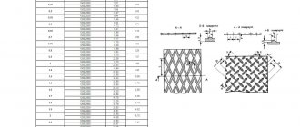
Fig. 1. Basic designations of parallel keys and keyways.
Table 1. Dimensions and maximum deviations of parallel keys and keyways according to GOST 23360-78.
| Shaft diameter d | Key section bхh | Keyway | Length l mm | ||||||||||
| Width b | Depth | Rounding radius r or chamfer s1 x 45° | |||||||||||
| Free connection | Nominal connection | Tight connection | Shaft t1 | Bushing t2 | |||||||||
| Shaft (H9) | Bushing (D10) | Shaft (N9) | Bushing (JS9) | Shaft and bushing (P9) | Nom.. | Nom. | Prev. off | no more | no less | ||||
| From 12 to 17 » 17 » 22 | 5×5 6×6 | +0,030 | +0,078 +0,030 | 0 -0,030 | ±0,015 | -0,012 -0,042 | 3,0 3,5 | +0,1 | 2,3 2,8 | +0,1 | 0,25 0,25 | 0,16 0,16 | 10-56 14-70 |
| St. 22 to 30 » 30 » 38 | 8×7 | +0,036 | +0,098 +0,040 | 0 -0,036 | ±0,018 | -0,015 -0,051 | 4,0 5,0 | +0,2 | 3,3 3,3 | +0,2 | 0,25 0,4 | 0,16 0,25 | 18-90 |
| 10×8 | 22-110 | ||||||||||||
| St. 38 to 44 » 44 » 50 » 50 » 58 » 58 » 65 | 12×8 | +0,043 | +0,120 +0,050 | 0 -0,043 | ±0,021 | -0,018 -0,061 | 5,0 | 3,3 | 0,4 | 0,25 | 28-140 | ||
| 14×9 | 5,5 | 3,8 | 36-160 | ||||||||||
| 16×10 | 6,0 | 4,3 | 45-180 | ||||||||||
| 18×11 | 7,0 | 4,4 | 50-200 | ||||||||||
| St. 65 to 75 » 75 » 85 » 85 » 95 | 20×12 | +0,052 | +0,149 +0,065 | 0 -0,052 | ±0,026 | -0,022 -0,074 | 7,5 | 4,9 | 0,6 | 0,4 | 56-220 | ||
| 22×14 | 9,0 | 5,4 | 63-250 | ||||||||||
| 24×14 | 9,0 | 5,4 | 70-280 |
Table 2. Limit deviations of dimensions (d + t1) and (d + t2).
| Height of keys | Maximum dimensional deviation | |
| d+t1 | d+t2 | |
| From 2 to 6 | 0 -0,1 | +0,1 0 |
| St. 6 to 18 | 0 -0,2 | +0,2 0 |
| St. 18 to 50 | 0 -0,3 | +0,3 0 |
Parallel keys with mounting on the shaft in accordance with GOST 8790-79.
Fig. 2. Basic designations of parallel keys with mounting on the shaft and keyways.
Table 3. Dimensions of parallel keys with mounting on the shaft according to GOST 8790-79.
| Width b (h9) | Height h (h11) | Rounding radius r or chamfer s1 x 45° | Diameter d0 | Length l2 | Length l (h14) | Screws according to GOST 1491-80 | ||
| no less | no more | from | before | |||||
| 8 | 7 | 0 25 | 0,40 | M3 | 7 | 25 | 90 | M3×8 |
| 10 | 8 | 0,40 | 0,60 | 8 | 25 | 110 | M3×10 | |
| 12 | M4 | 10 | 28 | 140 | M4×10 | |||
| 14 | 9 | M5 | 36 | 160 | M5×12 | |||
| 16 | 10 | M6 | 11 | 45 | 180 | M6×14 | ||
| 18 | 11 | 50 | 200 | |||||
| 20 | 12 | 0,60 | 0,80 | 56 | 220 | |||
| 22 | 14 | M8 | 16 | 63 | 250 | M8×20 | ||
| 25 | 70 | 280 | ||||||
| 28 | 16 | 80 | 320 | |||||
| 32 | 18 | M10 | 18 | 90 | 360 | M10×25 | ||
| 36 | 20 | 1,00 | 1,20 | 100 | 400 | |||
| 40 | 22 | M12 | 22 | 100 | 400 | M12×30 | ||
| 45 | 25 | 125 | 450 |
Segment keys according to GOST 8786-68.
Fig. 3. Basic designations of segmental keys and keyways.
Table 4. Dimensions and maximum deviations of segment keys and keyways according to GOST 8786-68.
| Shaft diameter d | Key dimensions b×h×D | Keyway | |||||||
| Transmitting torque | Fixing elements | Width b | Depth | Rounding radius r or chamfer s1 x 45° | |||||
| Shaft t1 | Bushing t2 | ||||||||
| Nom. | Prev. off | Nom. | Prev. off | no less | no more | ||||
| From 3 to 4 St. 4 » 5 | From 3 to 4 St. 4 » 6 | 1×1,4×4 1,5×2,6×7 | 1,0 1,5 | 1,0 2,0 | +0,1 0 | 0,6 0,8 | +0,1 | 0,08 | 0,16 |
| St. 5 » 6 » 6 » 7 | St. 6 » 8 » 8 » 10 | 2×2,6×7 2×3,7×10 | 2,0 | 1,8 2,9 | 1,0 1,0 | ||||
| St. 7 to 8 | St. 10 to 12 | 2,5×3,7×10 | 2,5 | 2,7 | 1,2 | ||||
| St. 8 to 10 » 10 » 12 | St. 12 to 15 » 15 » 18 | 3×5×13 3×6,5×16 | 3,0 | 3,8 5,3 | +0,2 0 | 1,4 1,4 | |||
| St. 12 to 14 » 14 » 16 | St. 18 to 20 » 20 » 22 | 4×6,5×16 4×7,5×19 | 4,0 | 5,0 6,0 | 1,8 1,8 | 0,16 | 0,25 | ||
| St. 16 to 18 » 18 » 20 | St. 22 to 25 » 25 » 28 | 5×6,5×16 5×7,5×19 | 5,0 | 4,5 5,5 | 2,3 2,3 | ||||
| St. 20 to 22 | St. 28 to 32 | 5×9×22 | 7,0 | +0,3 | 2,3 | ||||
| St. 22 to 25 » 25 » 28 | St. 32 to 36 » 36 » 40 | 6×9×22 6×10×25 | 6,0 | 6,5 7,5 | 2,8 2,8 | ||||
| St. 28 to 32 | St. 40 | 8×11×28 | 8,0 | 8,0 | 3,3 | +0,2 | 0,25 | 0,40 | |
| St. 32 to 38 | St. 40 | 10×13×32 | 10,0 | 10,0 | 3,3 |
Wedge keys according to GOST 24068-80.
Fig. 4. Basic designations of wedge keys and keyways.
Table 5.1 Dimensions and maximum deviations of wedge keys and keyways according to GOST 24068-80.
| Width b (h9) | Height h (h11) | Rounding radius r or chamfer s1 x 45° | Length l (h14) | Key head height | ||
| no less* | no more | from | before | |||
| 2 | 2 | 0,16 | 0,25 | 6 | 20 | — |
| 3 | 3 | 6 | 36 | — | ||
| 4 | 4 | 8 | 45 | 7 | ||
| 5 | 5 | 0,25 | 0,40 | 10 | 56 | 8 |
| 6 | 6 | 14 | 70 | 10 | ||
| 8 | 7 | 18 | 90 | 11 | ||
| 10 | 8 | 0,40 | 0,60 | 22 | 110 | 12 |
| 12 | 8 | 28 | 140 | 12 | ||
| 14 | 9 | 36 | 160 | 14 | ||
| 16 | 10 | 45 | 180 | 16 | ||
| 18 | 11 | 50 | 200 | 18 | ||
| 20 | 12 | 0,60 | 0,80 | 56 | 220 | 20 |
| 22 | 14 | 63 | 250 | 22 | ||
| 25 | 14 | 70 | 280 | 22 | ||
| 28 | 16 | 80 | 320 | 25 | ||
| 32 | 18 | 90 | 360 | 28 | ||
| 36 | 20 | 1,00 | 1,20 | 100 | 400 | 32 |
| 40 | 22 | 100 | 400 | 36 | ||
| 45 | 25 | 110 | 450 | 40 | ||
| 50 | 28 | 125 | 500 | 45 | ||
| 56 | 32 | 1,60 | 2,00 | 140 | 500 | 50 |
| 63 | 32 | 160 | 500 | 50 | ||
| 70 | 36 | 180 | 500 | 56 | ||
| 80 | 40 | 2,50 | 3,00 | 200 | 500 | 63 |
| 90 | 45 | 220 | 500 | 70 | ||
| 100 | 50 | 250 | 500 | 80 |
Continuation.
Table 5.2 Dimensions and maximum deviations of wedge keys and keyways according to GOST 24068-80.
| Shaft diameter | Key section bхh | Keyway | ||||||
| Width b | Depth | Rounding radius r or chamfer s1 x 45° | ||||||
| Shaft and sleeve (D10) | Shaft t1 | Bushing t2 | ||||||
| Nom. | Prev. off | Nom. | Prev. off | no less | no more | |||
| From 6 to 8 | 2x2 | 2 | 1,2 | +0,1 0 | 0,5 | +0,1 0 | 0,08 | 0,16 |
| St. 8 to 10 | 3x3 | 3 | 1,8 | 0,9 | ||||
| St. 10 to 12 | 4x4 | 4 | 2,5 | 1,2 | ||||
| St. 12 to 17 | 5x5 | 5 | 3,0 | 1,7 | 0,16 | 0,25 | ||
| St. 17 to 22 | 6x6 | 6 | 3,5 | 2,2 | ||||
| St. 22 to 30 | 8x7 | 8 | 4,0 | +0,2 0 | 2,4 | +0,2 0 | ||
| St. 30 to 38 | 10x8 | 10 | 5,0 | 2,4 | 0,25 | 0,40 | ||
| St. 38 to 44 | 12x8 | 12 | 5,0 | 2,4 | ||||
| St. 44 to 50 | 14x9 | 14 | 5,5 | 2,9 | ||||
| St. 50 to 58 | 16x10 | 16 | 6 | 3,4 | ||||
| St. 58 to 65 | 18x11 | 18 | 7 | 3,4 | ||||
| St. 65 to 75 | 20x12 | 20 | 7,5 | 3,9 | 0,40 | 0,60 | ||
| St. 75 to 85 | 22x14 | 22 | 9 | 4,4 | ||||
| St. 85 to 95 | 25x14 | 25 | 9 | 4,4 | ||||
| St. 95 to 110 | 28x16 | 28 | 10 | 5,4 | ||||
| St. 110 to 130 | 32x18 | 32 | 11 | 6,4 | ||||
| St. 130 to 150 | 36x20 | 36 | 12 | +0,3 0 | 7,1 | +0,3 0 | 0,70 | 1,00 |
| St. 150 to 170 | 40x22 | 40 | 13 | 8,1 | ||||
| St. 170 to 200 | 45x25 | 45 | 15 | 9,1 | ||||
| St. 200 to 230 | 50x28 | 50 | 17 | 10,1 | ||||
| St. 230 to 260 | 56x32 | 56 | 20 | 11,1 | 1,20 | 1,60 | ||
| St. 260 to 290 | 63x32 | 63 | 20 | 11,1 | ||||
| St. 290 to 330 | 70x36 | 70 | 22 | 13,1 | ||||
| St. 330 to 380 | 80x40 | 80 | 25 | 14,1 | 2,00 | 2,50 | ||
| St. 380 to 440 | 90x45 | 90 | 28 | 16,1 | ||||
| St. 440 to 500 | 100x50 | 100 | 31 | 18,1 |
Designations on the drawings
In the drawings, the designation of parallel keys is based on the GOST regulatory document. They are divided into keyways: high, normal height and guides. Their working faces are the lateral ones.
In the assembly drawing, the designation is made taking into account the shaft diameter, torque, cross-section and length.
For example:
Key 3–20Х12Х120 GOST 23360-78; Where 3 is the design, 20Х12 is the section, 120 is the length.
The designation of other types of keys in the images is carried out in the same way, based on the corresponding GOST standards developed for each individual model. The specified designation must clearly characterize the part, which is very important for obtaining a reliable connection. After all, even the slightest gap can cause rapid wear of working units and loss of efficiency during operation
Advantages and disadvantages
Like any type of connection, keyed connections have a number of advantages and disadvantages. The advantages of keyed connections include the simplicity of most types of keys. At the same time, installation and replacement of such a part is easy and quick. Thanks to this, they are widely used in mechanical engineering. Also provides protection function.
Disadvantages include weakening of the hub and shaft. It arises from increased stress and reduced cross-section. Also, the weakening of parts is caused by the cut groove, which reduces the axial strength of the shaft.
To minimize the shortcomings, you need to ensure that the key is not skewed in the groove. To do this, you need to ensure that there is no gap, which is done by individually manufacturing and adjusting the key. Because of this, any type of keyed joints are rarely used in large-scale production. If it is not possible to ensure the absence of misalignment, the working contact area decreases, as a result of which the degree of maximum load decreases.
Also, the presence of a gap causes a runout effect, especially at high speeds. This will lead to rapid wear of working parts. Because of this, such a connection is rarely used for rapidly rotating shafts. To select a suitable key, it is better to use the table of key connections.
Assembling keyed joints
Parallel keys must be replaced when:
- crushing of the side faces;
- weakening of the landing;
- collapse of the keyway.
Disassembly of a keyed connection can be done in various ways, depending on the design of the connection. To disassemble, make a threaded hole in the middle part of the key and screw a screw into it. When adjusting and assembling parallel keys, it is recommended to make a bevel on the surface of the key from the shaft side, to a length not exceeding the height of the key, and make a mark on the reverse side. An indispensable condition for the process of disassembling the key joint is maintaining the cleanliness and accuracy of the seats.
If the groove wall is slightly worn out, it is necessary to level the walls of the keyway until the correct shape is obtained and make a new key with an increased cross-section. Expansion of the keyway is allowed by an amount not exceeding 10-15% of the original size. When making a new key and repairing a keyway, processing should be carried out with the appropriate tool. Drilling of keyways must be done with a milling cutter.
Before assembly, the parts are cleaned and the fit dimensions are checked, the presence of nicks, burrs and other defects on the mating surfaces. Measuring the depth of the grooves, the height and correct installation of the keys is carried out using probes, templates, dial-type movement indicators and special stands.
The key is seated in the shaft groove with light blows of a copper hammer (or a soft metal hammer), under a press or using clamps. Skewing the key and cutting into the body of the groove is not allowed. The absence of lateral clearance between the key and the groove is checked with a feeler gauge, then the covering part (wheel, pulley) is installed and the presence of radial clearance is checked.
When assembling wedge keys, it is necessary to ensure that the key fits tightly to the bottom of the groove of the shaft and bushing and has gaps along its side walls. The upper edge of the wedge keys must be made with a slope along the length of 1:100. The slopes on the working surface of the key and in the groove of the bushing must coincide, otherwise the part will sit on the shaft with a skew. The accuracy of the key fit is checked with a feeler gauge on both sides of the bushing. During assembly, the grooves of the shaft or the surface of the key are sawed or scraped to prevent distortion and displacement. In the assembled connection, the head of the taper key should not reach the end of the hub by an amount equal to the height of the key. To prevent the wedge and tangential keys from falling out (when they are loosened), stops are installed on the screws at the heads. It should be noted the uncertainty of the forces that arise when pressing the wedge keys. This may damage the hubs of the male parts.
Dowels with a cross-sectional size of more than 28×16 mm must be checked for paint on the seats until five or more prints are obtained per square centimeter of surface. Before installing the key, the key and keyway must be cleaned and oiled. It is not allowed to install any pads in all types of keyed joints to achieve a tight fit of the keys.
Segmental keys are less susceptible to misalignment and do not require manual fitting (since the keyway is produced with a cutter corresponding to the size of the key); the groove for the segment key is deeper, which weakens the cross-section of the shaft.
In the assembled connection between the upper edge of the parallel key and the base of the hub groove (), the radial clearance must correspond to those given in the data. In connections with a wedge key (), the lateral clearance between the groove and the key should not exceed the values specified in.
Figure 4.1 – Gap when installing parallel keys
| Shaft diameter, mm | Radial clearance, mm |
| from 25 to 90 | 0,3 |
| from 90 to 170 | 0,4 |
| over 170 | 0,5 |
Figure 4.2 – Gaps when installing wedge keys
Table 4.2 – Lateral clearance values for wedge keys depending on the key size
| Normal dimensions of keys, mm | Side clearance, mm |
| b = 12…18; h = 5…11 | 0,35 |
| b = 20...28; h = 8…16 | 0,4 |
| b = 32…50; h = 11…28 | 0,5 |
| b = 60...100; h = 32…50 | 0,6 |
The guide keys are installed with additional fastening in the groove with screws; a looser fit is made in the groove of the moving parts.
Tolerances and fits of spline joints
Main parameters of spline connections
Spline connections, like keyed connections, are designed to transmit torque in connections between pulleys, couplings, gears and other parts with shafts. Unlike keyed connections, spline connections, in addition to transmitting torques, also center the mating parts. Splined joints can transmit greater torques than keyed joints and have less misalignment and displacement of slots and teeth. Find out more about the types of spline connections here.
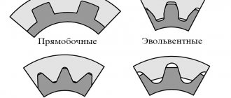
Depending on the tooth profile, spline connections are divided into connections with straight-sided, involute and triangular tooth profiles.
Splined joints with a straight-sided tooth profile are used for movable and fixed joints. The main parameters include:
According to GOST 1139-80*, depending on the transmitted torque, three types of connections are installed - light, medium and heavy series.
In spline joints with a straight-sided tooth profile, three methods are used for relative centering of the shaft and bushing (Fig. 3):
Rice. 3. Methods for relative centering of spline joints
Centering along the outer and inner diameters ensures good alignment of the parts during mutual movement. But centering along the outer diameter is also used for fixed joints, since there is no wear from axial movements in them.
Selection of tolerances and fits of spline connections
Rice. 4. Tolerance fields for spline connections
Straight-sided spline joints are typically controlled by complex feed-through gauges. In this case, element-by-element control is carried out with no-go gauges or measuring instruments. In controversial cases, control using a complex gauge is decisive. When using complex gauges, the hole is considered suitable if the complex gauge-plug passes, and the diameters and width of the groove do not exceed the established upper limits; the shaft is considered suitable if the complex ring gauge passes, and the diameters and thickness of the teeth do not exceed the established lower limit.
The designation on the drawings of straight-sided spline connections of shafts and bushings must contain:
The designation may not indicate tolerances for non-centering diameters.
Tolerances and fits of involute spline connections
To increase the durability of connections, improve centering and simplify milling (using the rolling method with one hob cutter when cutting splines of the same module, but different numbers of teeth and diameters), spline connections with an involute tooth profile are used.
However, with hardened shafts and bushings, splining teeth with an involute profile is unprofitable. In addition, the cost of broaching during finishing is higher than for teeth with a straight-sided profile.
The main advantages of involute spline connections compared to straight-sided ones are:
In spline involute connections, the sleeve is centered relative to the shaft according to:
Tolerances and fits when centering along the lateral surfaces of the teeth of involute joints have the peculiarity that two types of tolerances are established for the mating dimensions of the shaft tooth thickness s and bushing width e:
APPENDIX 3 (for reference). Maximum deviations for the dimensions of keyed connections
APPENDIX 3 Reference
Tolerances on the dimensions of keys and grooves must correspond to: for the height of the key - (OST 1024); for the groove depth of the shaft and bushing - (OCT 1015); for the length of the parallel key - (OST 1010 and GOST 2689-54); for the length of the shaft groove for the parallel key (OST 1010).
The maximum deviations for the dimensions of the keys, grooves on the shafts and in the bushings (hub) in width must correspond to those indicated in Tables 1 and 2.
Table 1
| Type of connection | Maximum dimensional deviation | Purpose of landings |
| dowels | shaft groove | sleeve groove |
| Fixed tension on the shaft sliding in the sleeve | For individual and serial production (general engineering) | |
| Fixed tension along the shaft, running in the bushing | For mass production (automotive industry) | |
| Fixed, tight along the shaft, running in the bushing | For guide keys |
table 2
| Nominal width of key and groove, mm | Maximum deviation of the size of the grooves of the shaft and bushing, microns | |||
| top | lower | top | lower | |
| From 1 to 3 | -10 | -50 | +55 | +10 |
| St. 3 » 6 | -10 | -55 | +65 | +15 |
| 6 » 10 | -15 | -65 | +75 | +20 |
| » 10 » 18 | -20 | -75 | +85 | +25 |
| » 18 » 30 | -25 | -90 | +100 | +30 |
| » 30 » 50 | -32 | -105 | +120 | +35 |
| » 50 » 80 | -40 | -125 | +140 | +40 |
| » 80 » 120 | -50 | -150 | +160 | +45 |
Keyed connections with parallel keys. Dimensions, mm
Parallel keys are divided into:
- ordinary,
- tall,
- guides.
Ordinary and high keys are used in fixed joints.
Table 1a
Guide keys with mounting on the shaft according to GOST 8790-79 (ST SEV 5612-86)
If axial movement of parts is necessary, guide keys of the same cross-section as ordinary ones are used, but they are secured to the shaft with screws.
In table 1, a and b show the cross-sectional dimensions of ordinary prismatic and guide keys and grooves.
Table 1, b
Three versions of keys are provided:
- with rounded ends;
- with flat tors;
- with one rounded end and the other flat end.
Symbols of ordinary and guide parallel keys
An example of a designation for a key of version 1 according to GOST 23360-78 and GOST 8790-79, respectively, with dimensions b=18mm, h=11mm, l=70mm:
Key 18x11x70 GOST 23360-78 Key 18x11x70 GOST 8790-79
The same, execution 2:
Key 2 - 18x11x70 GOST 23360-78 Key 2 - 18x11x70 GOST 8790-79
In table 2 shows a number of key lengths provided for by GOST 23360-78 and GOST 8790-79.
Application
The main application of keyed connections is mounting on a shaft using a grooved connection. In most cases, the keyway resembles a wedge. This type of connection of parts allows the shaft and hub not to rotate relative to each other’s axis. The fixed position of the hub to the shaft with a key allows for high efficiency when transmitting force.
Most often, keyed connections can be found in mechanical engineering, during the construction of machine tools. It is often used in the production of cars and other mechanisms, where increased reliability of fixing machine parts is required. High reliability is achieved thanks to the function of the shaft safety unit with keyway.
The key acts as a fuse in cases where the maximum torque level is exceeded. In such cases, the key is sheared, absorbing the excessive load and removing it from the shaft and hub.
Due to its properties, it has become widespread in mechanical engineering; it is characterized by high efficiency, ease of manufacture and installation, and low cost. Such characteristics are especially important in industrial production, especially in agriculture. At the height of the season, there are often cases of breakdowns of individual components that need to be replaced as quickly as possible. Most often found in baler units.
Considering all of the above, the main positions for which a key is needed are highlighted:
- Ensuring the safety of connected nodes under increased loads.
- Achieving a high degree of fixation of individual elements of a mechanical assembly.
- Performs the function of preventing rotation of the unit and hub.
- The reliability of such a connection exceeds the reliability of analogues when fixing the shaft with parts.
In general, you can find a keyed connection in almost any complex mechanism, which is due to its technical characteristics.
Key material
For the manufacture of keyed joints, calibrated rolled metal is used. The most commonly used steel is grade 45. It is a regular type of carbon steel, which is often used to produce high-strength parts. The steel is used in the form of a 1 m long bar.
In some cases, carbon steel grade 50 can be used. It is necessary when increased strength properties of the resulting keys are required. Less commonly used are alloy steels, for example, grade 40x, which is characterized by a high hardness index achieved by heat treatment.
Steel blanks are processed using cutters, drilling machines, chopping machines, grinders and other tools. The machines used have a control unit that allows, using numerical programs, to produce a part with the required parameters.
The price of the resulting key is quite low, so purchasing the necessary part is quite easy. But in some cases, when there is an urgent need to obtain a key, you can make it yourself. Most often, such a need arises in agriculture, where during seasonal work breakdowns often occur that need to be repaired. At the same time, the nearest points of sale of the necessary parts are located at a distance of several tens of kilometers.
With a small amount of tools on hand and a blank made of the appropriate material, you can quickly make a temporary replacement. If the technical specifications are observed, the resulting part can fully replace the factory one, but it is best to purchase a key of the required strength and geometric parameters at the first opportunity. This is necessary to avoid premature wear of the mechanisms.
It is better to use different types of wood as a material; for a dowel, a softer material than the main one is suitable. This will protect the main structure from damage in case of increased load. It is easier to replace a key than a large structural unit.
To prevent moisture from penetrating into reinforced concrete structures, special dowels called waterstop are used. They are made from high quality rubber and PVC. This allows you to achieve the required degree of waterproofness and resistance to solutions of aggressive chemicals.
Preparatory stage
The bushing is installed in a three-jaw chuck. Before performing chiselling, you must first prepare its internal and external chamfer with a boring cutter. They are made only on the side from which the slotting tool will enter. This is a simple process, familiar even to an amateur turner, and therefore does not require separate consideration.
After preparing the chamfers on the machine, you need to set the minimum speed to prevent spindle rotation. On many machines, the jaw chuck can give play under load, so in this case it is necessary to install a spacer. To do this, place a bolt and nut of suitable height under it. When unscrewing it, the length of the stop increases, so it is pressed tightly against the cartridge, thereby eliminating the rolling.
The slotting cutter is lightly clamped in the tool holder. It aligns the bushing in the center, after which it is necessary to make fine adjustments. To do this, it is inserted into the bushing, moving longitudinally with the caliper along the slide. The resulting scratch should run along the bushing hole from one edge to the other. There should not be a section without a scratch in the cut line. If it exists, then this indicates the presence of a distortion. When the cutter is positioned correctly, it must be clamped very tightly, since the load during chiselling is much higher than during standard turning work.
SHAPE, DIMENSIONS AND MAXIMUM DEVIATIONS OF KEYS
- width; - height; - chamfer; - length
Damn.1
Table 1
mm
| h 9 | h 11 | * | ** | ||||
| nominal size | prev off | nominal size | prev off | min. | Max. | row | |
| from | before | ||||||
| 5 | 0 -0,030 | 3 | 0 -0,060 | 0,25 | 0,40 | 10 | 56 |
| 6 | 4 | 0 -0,075 | 0,25 | 0,40 | 14 | 70 | |
| 8 | 0 -0,036 | 5 | 0,25 | 0,40 | 18 | 90 | |
| 10 | 6 | 0,40 | 0,60 | 22 | 110 | ||
| 12 | 0 -0,043 | 6 | 0,40 | 0,60 | 28 | 140 | |
| 14 | 6 | 0,40 | 0,60 | 36 | 160 | ||
| 16 | 7 | 0 -0,090 | 0,40 | 0,60 | 45 | 180 | |
| 18 | 7 | 0,40 | 0,60 | 50 | 200 | ||
| 20 | 0 -0,052 | 8 | 0,60 | 0,80 | 56 | 220 | |
| 22 | 9 | 0,60 | 0,80 | 63 | 250 | ||
| 25 | 9 | 0,60 | 0,80 | 70 | 280 | ||
| 28 | 10 | 0,60 | 0,80 | 80 | 320 | ||
| 32 | 0 -0,062 | 11 | 0 -0,110 | 0,60 | 0,80 | 90 | 360 |
| 36 | 12 | 1,00 | 1,20 | 100 | 400 |
_____________ * Chamfers are removed only on the longitudinal edges and on the rounded ends of the keys, the remaining edges are dulled. ** Key lengths are selected from the range: 10, 12, 14, 16, 18, 20, 22, 25, 28, 32, 36, 40, 45, 50, 56, 63, 70, 80, 90, 100, 110, 125, 140, 160, 180, 200, 220, 250, 280, 320, 360 and 400 mm.
Set of tools
To perform the work, in addition to the machine, you will need:
- boring cutter;
- slotting cutter;
- oil for lubrication.
Any boring cutter can be used, of course, within the capabilities of the sleeve diameter. As for the slotting tool, its cross-section is selected to match the required width of the keyway. Lubricating oil is only required if you have to work with hard metal. For soft steels, provided that high-quality cutters are used, it is not necessary, since chamfer boring and chiselling does not cause critical overheating, which can accelerate the abrasion of the cutting edge of the tool.
Designations on the drawings
In the drawings, the designation of parallel keys is based on the GOST regulatory document. They are divided into keyways: high, normal height and guides. Their working faces are the lateral ones.
In the assembly drawing, the designation is made taking into account the shaft diameter, torque, cross-section and length.
Key 3–20Х12Х120 GOST 23360-78; Where 3 is the design, 20Х12 is the section, 120 is the length.
The designation of other types of keys in the images is carried out in the same way, based on the corresponding GOST standards developed for each individual model. The specified designation must clearly characterize the part, which is very important for obtaining a reliable connection. After all, even the slightest gap can cause rapid wear of working units and loss of efficiency during operation
Steel 45 calibrated
Calibrated steel St45 has long proven itself to be a very durable, reliable raw material. Blanks made from this type of material are excellent for their subsequent processing and production of all kinds of parts and spare parts for various types of equipment. As a rule, calibrated steel 45 serves as the basis for creating shafts, couplings, plungers, flywheels and other parts. Since it is able to function in extremely difficult working conditions, it can be safely used in a variety of industrial production sectors:
- In the construction of buildings and structures
- In the production of machines and special equipment
- For the manufacture of ships and aircraft
Due to its chemical composition, which contains nickel, phosphorus and chromium, calibrated steel 45 is resistant to corrosion, although not very high, since the percentage of these substances is small. And the presence of such components as carbon, silicon, manganese, sulfur, arsenic and copper in the structure of this alloy allows it to withstand various mechanical stress. If necessary, St45 can be replaced with brands 40X, 50G2, St50 that are approximately similar in characteristics.
Features and application of key material
A key is an oblong-shaped part of machines and mechanisms inserted into the groove of the connected parts of a key connection to transmit torque.
Key material serves as raw material for manufacturing
prismatic keys according to GOST 23360-78. Such keys are used as a wedge locking element in axial rotation parts of mechanisms and equipment to prevent them from turning and transmitting rotation from one element to another. At the same time, the key is a kind of fuse against overloads when the rotation is jammed - in such a situation, the key takes on all the excess force, and it is “cut off”, keeping expensive gears, shafts, pulleys and other parts of the mechanisms intact.
The key material is calibrated cold hardened steel 45. The cutting length is 1 meter. It is used as a raw material for the manufacture of parallel keys in accordance with GOST 23360-68.
Assortment of sections of key material
Sales from 1 meter. Shipping within Ukraine by transport companies.
You can download GOST 8787-68 in the “Specification” section
Characteristics of key steel
The above information indicates that the steel for keys must have certain performance characteristics. From the name of the material you can immediately determine its scope of application. Among the features we note the following:
- Metal keys are often produced using metal that meets GOST 8787-68.
- Foreign manufacturers take into account the DIN standard
- In most cases, rolled keys, represented by structural carbon steel, are used.
- A special feature is that the surface layer has better performance characteristics.
- The basic characteristics can be improved by carrying out various types of heat treatment. Hardness is often increased by quenching or tempering.
The grade of steel used lends itself well to cold and hot drawing. Due to this, a volumetric or combined calibration is released.
The 8×7 key material has become quite widespread. The use of standards at the time of production of blanks allows us to significantly simplify the task of producing an intermediate element
When choosing a material, pay attention to the following points:
- Hardness of the surface layer.
- Resistance of the material from environmental influences.
- Processability degree.
Common alloys can be used for the manufacture of prismatic and other versions of intermediate elements that are installed to transmit force. It is worth considering that most often keyed steel is used to create rectangular bars of various sizes that are installed on the shaft.
The classic version is represented by the St45 brand. The key features include:
This is structural carbon steel of ordinary quality, the cost of which is relatively low. Traditionally used in the manufacture of critical parts. Do not pay attention to the fact that this grade is not suitable for welding.
In addition, the St50 grade can be used, the properties of which do not differ significantly from the previous version.
In cases where it is necessary to significantly increase the strength of a joint, attention should be paid to the possibility of using alloyed alloys. Adding certain chemical elements to the composition can significantly improve performance characteristics
An example is the 40X brand, which is characterized by the following features:
- Hardness varies between 35-45 HRC. To increase this indicator, heat treatment is carried out, as well as tempering to reduce the likelihood of internal stresses.
- The addition of chromium allows you to slightly increase the degree of protection of the material from exposure to high humidity. This point determines that corrosion does not appear on the surface over a long period of use of the product.
- A carbon concentration of around 0.4% ensures the required strength and hardness of the product. At the same time, other substances may be included in the composition in small concentrations, thereby ensuring the required performance characteristics.
Other alloys with special performance characteristics, for example, with good resistance to elevated temperatures, can also be used. The choice is made depending on performance characteristics and many other points.
Varieties
The main criterion for choosing a parallel key is what type of connections it is intended for.
In the event that the connection is stationary, embedded parallel keys are used. In moving joints, guides or sliding feather keys are used. The use of guides is relevant when the hub moves along the longitudinal axis with the shaft, while it slides along the groove itself. The sliding type involves rigid fastening into a groove and movement along it.
In production, the production of keys of all types must be carried out in accordance with the relevant GOSTs. These documents contain recommended dimensions for products in accordance with standard shaft sizes.
In cases where the shaft or spindle has a non-standard diameter, detailed calculations of tolerances and fits for the groove should be carried out.