Selection of equipment and tools
Cutting is performed on machines:
- milling;
- planing;
- slotting;
- turning;
- lingering
The parts are then polished on grinding machines.
In small-scale and individual production, spline cutting is very often carried out on spline milling or gear hobbing equipment using a hob cutter and the rolling method. The use of such a tool is effective for both straight-sided and involute splines.
A horizontal milling machine for cutting splines is used in conjunction with a shaped disc cutter. For simultaneous cutting of several grooves, a dividing head is used. It is worth noting that this method is used extremely rarely for the manufacture of splines due to inaccuracies in pitch and width. It would be advisable to rough-process the part on a horizontal milling machine with a disk cutter, leaving allowance for finishing and grinding. Finishing of the grooves is carried out with special end mills, and for a triangular spline connection, triangular cutters are used.
The running-in method using a cutter is used. For the high quality of the resulting surfaces, gear shaping equipment is used in mass production.
In addition to slotting machines, planing and broaching machines have become widespread in the mass and large-scale production of spline joints. Such equipment is several times more efficient and productive than milling machines. Planing cutting is carried out using a set of cutters, the number and dimensions of which depend on the number of teeth, the width and depth of the joint grooves. When broaching, a tool called a broach is used. This tool has several cutting teeth of different heights, which, when moving forward, cut off part of the metal from the workpiece.
For the manufacture of involute joints, cold rolling is used using special roller heads. This tool produces products with a large number of teeth. The cold rolling method is 10 times more efficient than milling.
After cutting the teeth and heat treatment, all products are ground. This allows you to achieve the required roughness and avoid snagging of mating parts during operation. For grinding use the following tool:
- shaped circle;
- disk circle;
- conical circle.
In some cases, a mandrel is used to grind internal surfaces.
Spline connections and methods for their processing
Three methods of centering rectangular spline joints are used: a) centering along the outer diameter; it is used when the hardness of the hole is low and can be processed by broaching, and the shaft is not subject to significant deformation during heat treatment; b centering along the internal diameter; produced with high hole hardness and significant shaft deformations, which require grinding to eliminate; c) centering along the width of the slot; used when the hole has high hardness and minimal clearances on the side surfaces are required. Centering of involute and triangular spline connections is carried out only according to the profile of the splines with guaranteed clearances along the diameters of the depressions and projections. Processing of splines on external surfaces is carried out using the dividing method or the rolling method. Using the dividing method, splines are milled on horizontal milling machines with a set of cutters or shaped cutters. This method is also used when grinding splines on a spline grinding machine (Figure 2).
Spline milling machines using the division method are equipped with precise dividing devices that, after each double stroke, rotate the part to machine the next spline. Using the rolling method , splines are cut on spline milling or gear hobbing machines with a single-thread hob cutter, the profile of which, when rolled with the workpiece, forms splines of the required shape and size (Figure 3). Rectangular, triangular and involute splines are processed using the rolling method. Compared to the division method, this method is more productive.
Short splines at the ends of the shafts near the protrusions that do not allow the use of a cutter are processed on gear shaping machines with special cutters. To increase the productivity of processing splines on external surfaces, spline planing and broaching machines are used, and knurling is also performed. Spline grinding is used to process shafts that, after heat treatment, have deformation and high hardness, which does not allow the splines to be machined with a milling cutter. The most common method for machining splines on internal surfaces is to broach the spline holes with a combination spline broach or set of broaches. A combined broach is used to process the inner surface of the spline hole and splines. Broaches can only process parts of low hardness, so broaching of splines is carried out before heat treatment. After heat treatment, the splines are calibrated using firmware (with a hardness of HRC no more than 35). For spline holes, when centering the parts along the inner diameter of the shaft, after heat treatment, grind the inner surface of the spline hole.
Menu
Write or call until 21:00 Moscow time:
[email protected] [email protected] +7(903)-982-12-16
©Project-Tekhnar, 2010-2021 All works, drawings and related materials belong to their authors and are provided for informational purposes only. TIN550705958503
Spline connection
The use of a spline connection is one of the methods of rigidly transmitting torque.
Splines, compared to keyed connections, have several advantages - better strength, accuracy and manufacturability.
Keys need to be adjusted, so they are recommended for use in single or small-scale production. Splines, unlike keys, are interchangeable and are recommended for use in large-scale and mass production.
Splines are considered a more technologically advanced connection than a key; internal splines are made by broaching, external splines by milling (with hobs), chiselling, and planing.
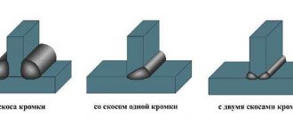
The technique uses rectangular, triangular, trapezoidal, and involute splines.
Rectangular splines are the most common.
Calculation of connections
The calculation of straight-sided splines and a table of standardized sizes are included in GOST 1139-80. For involute spline connections, GOST 6033-80 is used. It provides for fit along the outer diameter and side surface.
Centering along the inner radius of involute connections is used exclusively for theoretical calculations. The practical production of such involute joints is more complex and requires specialized finishing by grinding to the desired size and tooth shape.
Fit when centered on outer diameter:
Df – size at the top of the tooth;
da – the largest size according to the sleeve.
For use as a centering lateral involute surface:
Before determining the module, the nominal diameter of the shaft is calculated and the nearest normalized one is selected. Afterwards, a verification calculation is carried out, confirming the correctness of the choice of the involute connection.
There are 2 types of numbers in the table of normalized involute shafts. Preferred modulus values for different diameters are highlighted in bold or in color. For example, the smallest module for this diameter and the largest in value are not recommended. The diameter values themselves are also placed in 2 rows. The sizes from the first one are better. They are widely used, easier to finish, and there is a set of conventional tools used for cutting teeth. Parts from the initial series are provided with standardized rings, fasteners and other parts for assembling the unit.
The calculation for the cross-section of an involute connection, the designation of the shaft radius, is performed based on the smallest diameter for torque, bending strength and dynamic loads. The nominal diameter of the connection is calculated using the formula:
Where D is the outer diameter;
D? – nominal diameter;
When centering an involute connection - surfaces from the side
taking into account the gaps
The angle of the tooth profile of the involute connection according to GOST is 30°; if performed according to the Industry Standard, an involute inclination of 20° is allowed. Such engagement is found in old equipment from some companies working according to industry standards for the heavy automotive industry.
When calculating the cross-sectional strength of a tooth, constructing an involute and calculating loads on splines is carried out according to the method for spur gears. A correction indicator is introduced because the area for work is larger. All teeth interact simultaneously and every time under load. Execution errors during processing cannot ensure identical connection of virtually all side surfaces. A calculated indicator of 0.75 is introduced when centered on the surface from the side with accuracy of 9 and 8 qualifications.
If you find an error, please select a piece of text and press Ctrl+Enter.
Centering and landing
If the spline involute connection is centered along the outer radius, the main dimensions are calculated using the formula:
Read also: Homemade tool box for the car
where d is the diameter of the pitch circle;
m – modulus of the tooth and bushing cavity;
z – number of teeth.
The calculation of the nominal pitch circle for tool setting is calculated using the formula:
s =е=0.5π m + 2х m tan α;
s – nominal pitch circle on the shaft;
e – pitch circle along the bushing cavity;
x – displacement of the shape of the original contour;
ɑ is the involute angle of the tooth; for spline joints it is 30°.
For involute splines, the size of the offset from the original contour is calculated:
And the nominal size along the sleeve depressions is equal to the maximum diameter when centered along it:
When centering along the side surfaces of the teeth:
da – nominal diameter of the shaft, tooth tips;
D – outer size of the bushing cavity;
The tolerance for off-center dimensions depends on the type of thermal and surface treatment and is determined according to the table of maximum deviations, which is available in OST 1 00086-73
On the assembly drawing they are indicated by formulas, for example, the device assembly and the parts in the connection: a shaft with a pitch circle diameter of 4 mm and a tooth module of 0.5.
When centering along the outer diameter –
When centered along the side surface of an involute connection -
Where – 8 is the number of teeth;
S4 – coefficient taking into account the design of the involute shape.
The technical accompanying documentation indicates the characteristics of the splines:
In the drawing of the part, the designation for the shaft is:
Similar value for the bushing hole:
All “designations are given for connection with an outer shaft diameter of 6 mm.
Characteristics of spline connections
According to their design and method of transmitting torque, spline joints can be classified as multi-keyed. Several planes of interaction during rotation, but instead of a large number of grooves and keys in them, there is only a splined shaft and bushing. There are no keys; they are replaced by slotted grooves and teeth cut directly on the mating parts. The design can significantly reduce manufacturing errors and makes it possible for the sleeve to move along the shaft axis without stopping the radial movement.
The dimensions of the splines are determined by the internal diameter of the shaft, their number and shape. In a spline connection, several contact planes are formed. The ability to transmit high torque increases several times compared to keys.
The spline tooth is cut with cutters on gear cutting machines and by broaching. For moving units, subsequent grinding of the side surfaces is done. The length of the teeth can be any; for fixed spline joints it is equal to the height of the wheel hub. When the gear slides along the axis, the length of the cut protrusions on the shaft is determined by the size of the gear movement, its height and the technological allowance equal to the radius of the cutter for its exit during processing.
The diameter of the shaft along the outer surface is equal to the size of the sleeve along the depressions. The splined bushing exactly copies the shaft profile with its hole and fits tightly onto it. Spline grooves along the hole are cut on a slotting machine. The manufacturing technology is lengthy and requires great precision, which a cutter cannot provide, since the length of the cutter is large relative to its cross-section. When you try to speed up processing, make more entry and feed, the tool is pressed out, the size turns out to be minus.
When designing a unit and selecting pairs, the main parameter is the internal diameter of the splines. It is designed for torsion and bending. The splined bushing is subjected to less force. It is selected from the directory. The parts are made from medium-carbon low-alloy steels: St 45, St 40Х, St 40ХН. They have relatively high toughness and low brittleness in the normalized state and after volumetric hardening in air with a hardness of 320–350 HB.
The number of teeth during design can be determined using tables. They are divided for each internal diameter into 3 groups according to loads:
- light;
- average;
- heavy.
The more torque you need to transmit, the higher the spline itself and the greater their number. Due to this, the contact area increases.
Gear connections are calculated taking into account manufacturing errors. There is a connection gap between the surfaces of the mating parts. When the driving part is rotated, it moves in the opposite direction from the direction of the force. Ideally, all surfaces are in contact and loaded equally. In fact, gear joints are manufactured with an error of 0.01–0.03 mm, depending on the size and processing method. The coupling touches more with one plane and less with others. When calculating strength, a correction factor is selected from the table, which allows you to calculate the parameters of parts for strength, taking into account uneven load forces.
The gap in the connection determines the size of the idle stroke. Starting to move, the leading part first selects a gap between the working planes, then the force action and rotation of the driven part and the entire assembly begins.
Advantages and disadvantages
When designing mechanisms that transmit rotation with high loads, they most often choose a splined connection. It has enormous advantages in certain cases and can replace several keyed joints. There are also disadvantages. It is necessary to weigh all the arguments for and against when choosing a connection method.
Compared to keys, the advantages of spline connections include:
- reliability under shock loads and vibration;
- possibility to reduce the length of the hub;
- small radial clearances;
- increase in service life;
- no shear load and low bending load due to the large contact patch;
- several lines of application of forces, the ability to transmit large forces by shafts with a small diameter;
- axial movement;
- there are only 2 parts in the connection;
- compactness;
- precise alignment.
The splines are manufactured in accordance with GOST and Standards, have strictly standardized dimensions and the parts for the connection are easy to select. Simplified assembly of components and fitting of parts.
The disadvantages of spline connections include:
- high cost of parts;
- complex manufacturing technology;
- use of special equipment and tools.
When overloaded, the key is simply cut off, preventing the transfer of increased load to the working mechanism and preventing its breakage. The part is simple and cheap, easy to change.
In spline joints, in an emergency, a tooth or the entire machine may break. Replacing parts is difficult and expensive.
Involute splines
Involute splines cause a lower stress concentration compared to straight-sided splines. A splined connection reduces the endurance of the shaft less than a keyed connection.
Involute splines cause a lower stress concentration compared to straight-sided splines. A spline connection reduces shaft fatigue resistance less than a keyed connection.
Involute splines in the bushing are usually cut on gear shaping machines. Currently, broaching of involute splines has been introduced into mass production. Pulling involute splines is many times more productive than chiselling. The disadvantage of this method is the difficulty of manufacturing a broach with an involute profile.
Involute splines ensure precise centering of the mating parts and have increased strength, since the radius in the cavity can be significantly larger than that of splines of other profiles, which reduces stress concentration at the base of the tooth (see Chap.
Involute splines cause a lower stress concentration compared to straight-sided splines. A splined connection reduces the endurance of the shaft less than a keyed connection.
Involute splines are teeth with an involute profile.
Involute splines cause a lower stress concentration compared to straight-sided splines. A splined connection reduces the endurance of the shaft less than a keyed connection.
Involute splines (see Fig. 283, b) are teeth of an involute profile, characterized by modulus m and engagement angle a. Centering is usually along the side edges. The fit can be interference, clearance or centering. Centering along the outer diameter of the splines is less commonly used.
Involute splines with a rounded cavity (Fig. 299, b) can be considered as a special case of triangular profile splines. The voltages in them are determined from the diagram in Fig. 294, b for the corresponding values of a 2a and pH.
Involute splines with a rounded cavity (Fig. 285 6) can be considered as a special case of triangular profile splines. The voltages in them are determined from the diagram in Fig. 281 6 for the corresponding values of a 2a0 and pc.
Involute splines with a rounded cavity (Fig. 285 6) can be considered as a special case of triangular profile splines. The voltages in them are determined from the diagram in Fig. 281 6 for the corresponding values of a 2o0 and pc.
Straight-sided and involute splines are used in movable and fixed joints.
In addition, involute splines are relatively easy to machine using the same principle as gears.
In addition, involute splines are relatively easy to machine, similar to the machining principle of gears.
In terms of overall strength, involute splines are somewhat inferior to triangular splines with an optimal profile.
Splines - GOST designations
Splined joints are called multi-keyed, in which the keys are made as one piece with the shaft, which makes it possible to transmit greater torques compared to a keyed joint. In addition, the spline connection provides good mutual centering of the bushing (wheel) and shaft, which is very important for shafts with a high number of revolutions.
Connections with straight-sided and involute tooth profiles have been standardized. The first connection is most widely used. The dimensions of straight-sided spline connections are established by GOST 1139-80* (ST SEV 187-75 and 188-75), which provides three designs - 1, 2, 3 and three series of connections - light, medium and heavy. Main parameters : number of teeth z, internal diameter d, external diameter D, tooth width b (Fig. 8.84). For the light and medium series z=6, 8, 10, for the heavy series - 10, 16 and 20. The surfaces of the shaft and sleeve teeth can touch (center) along the outer diameter D (with the formation of a gap along the inner diameter, Fig. 8.85, a) , along the inner diameter d (with the formation of a gap along the outer diameter, Fig. 8.85, b) and the side sides of the teeth (with the formation of gaps along the outer and inner diameters, Fig. 8.85, c). Designation of the bushing when centered along the inner diameter d: d — 8X36H7X40H12X7D9, where d— indicates the type of centering; 8 - number of teeth; 36 — internal diameter with tolerance range H7; 40 - outer diameter with tolerance range HI2; 7 — tooth width with tolerance range D9; the same for shaft d—8X36e8X X40a11X7f8, where e8, all and f8 are tolerance fields d, D, b, respectively. The designation does not reflect the design of the tooth - A, B or C (shown on the working drawing or decided by the technologist), but the series (set by the designer based on calculations) determine the values of z, d and D; in this example, the numbers 8, 36 and 40 belong to the light series.
In training drawings, they are usually limited to indicating the number of teeth, the dimensions of the internal and external diameters and the width of the tooth: 8X36X40X7. A spline involute connection with a profile angle of 30° (GOST 6033-80*) provides for basic centering along the side surfaces of the teeth (Fig. 8.86) and the permissible - by outer or inner diameters. Main parameters: nominal diameter D, modulus t and number of teeth z. Examples of notation:
- connections - 50X2X9H/9g GOST 6033-80;
- bushings - 50X2X9 N GOST 6033-80;
- shaft - 50X2X9g GOST 6033-80,
where 50 is the nominal diameter, 2 is the module, 9H and 9g are the tolerance fields. The number of teeth is not indicated, since it is determined by the values of D, etc. The type of centering (in the example, along the side surfaces of the teeth) is determined by the values of the tolerance fields.
In training drawings, they are usually limited to indicating D, t and the designation of the standard. Spline connections are depicted in accordance with GOST 2.409-74 * (ST SEV 650-77) in a simplified manner, as shown in Fig. 8.87, a (on the shaft), fig. 8.87.6 (in the hole) and fig. 8.88 (in connection). In images of involute connections, a dividing circle is added, as in Fig. 8.88.
On drawings containing non-standardized spline connections (for example, with a triangular tooth profile), an image of the tooth profile with cavities (splines) with all the necessary information is placed (Fig. 8.89).