Application
The main application of keyed connections is mounting on a shaft using a grooved connection. In most cases, the keyway resembles a wedge. This type of connection of parts allows the shaft and hub not to rotate relative to each other’s axis. The fixed position of the hub to the shaft with a key allows for high efficiency when transmitting force.
Most often, keyed connections can be found in mechanical engineering, during the construction of machine tools. It is often used in the production of cars and other mechanisms, where increased reliability of fixing machine parts is required. High reliability is achieved thanks to the function of the shaft safety unit with keyway.
The key acts as a fuse in cases where the maximum torque level is exceeded. In such cases, the key is sheared, absorbing the excessive load and removing it from the shaft and hub.
Due to its properties, it has become widespread in mechanical engineering; it is characterized by high efficiency, ease of manufacture and installation, and low cost. Such characteristics are especially important in industrial production, especially in agriculture. At the height of the season, there are often cases of breakdowns of individual components that need to be replaced as quickly as possible. Most often found in baler units.
Considering all of the above, the main positions for which a key is needed are highlighted:
- Ensuring the safety of connected nodes under increased loads.
- Achieving a high degree of fixation of individual elements of a mechanical assembly.
- Performs the function of preventing rotation of the unit and hub.
- The reliability of such a connection exceeds the reliability of analogues when fixing the shaft with parts.
In general, you can find a keyed connection in almost any complex mechanism, which is due to its technical characteristics.
Key material dimensions
During production, the dimensions of the key material are taken into account. In most cases, the rod is delivered to the production site. Its length can be about 1000 millimeters, in some cases it is produced to order. The most common key sizes are:
- 4×4.
- 5×5.
- 22×22.
- 25×25.
- 32×18.
- 40×40.
Do not forget that weight also depends on size. In addition, various alloys are used in the production of products of certain sizes. The size of the connecting element is selected depending on the load that will be applied. In addition, the size is influenced by the dimensions of the connected products.
At the time of product release, quality control is carried out using several different methods, including visual inspection.
The shape largely depends on the area of application of the product in question. The following types are distinguished:
- Wedges.
- Prismatic.
- Segmental.
- Tangential.
- Cylindrical.
Steel is characterized by fairly high ductility to machining. In most cases, the product is obtained from a workpiece, which is a rod.
Types of keys
The main types of keys are divided into two types: stressed and unstressed. Among which are the following types of keys:
- Wedges. A special type that differs in the angle of inclination of the upper edge. In general, the division into types is based on the classification of key joints. It is installed in the groove using physical force, using the impact method. The use of this type of connection allows you to achieve the required voltage. The cut wedge, being in the groove, expands it from the inside. Due to the pressing force, the shaft and hub rotate together. It is used quite rarely, since its use requires individual adjustment. This can be considered a disadvantage for mass production of mechanisms. The main purpose is to use it in low-speed transmissions and fixed connection units.
Among the wedge keys there are:- mortise;
- on a flat;
- friction;
- without head and with head.
- Segmental. They are produced in the form of a segment plate driven into a groove. Produced by milling. They are widely used in production, as they are easy to manufacture, do not require special precision when cutting and are easy to install. It differs in installation in a deeper groove, in comparison with analogues. A deep groove is not suitable for heavy loads, as it significantly reduces the strength of the shaft, so it is used for small torques.
Long hubs can have multiple keys installed because they have a fixed length. Perform a safety function against shearing and crushing. - Prismatic. They are distinguished by parallel edges that are installed in a groove and fix the hub. In such cases, the working faces are the lateral ones. They are a non-stressed type of keyed joints, so there is a possibility of corrosion at the joint. To avoid corrosion, the coupling and shaft are connected with interference. The ends are usually produced with rounded or flat ends. For a rounded type, the working surface is considered to be the length of the straight edges. The groove is cut using a cutter. The force is transmitted by pressing the surface of the groove onto the key, which transmits torque to the hub groove. This type of parallel key connection is often used for moving connections, so additional fastening with screws is used. Like many other types, it functions as a fuse during crushing and shearing.
- Cylindrical. The pins in such keys are made in the form of cylinders. I work in tension with a hole at the end of the shaft, which is drilled to fit the corresponding key sizes. Used in cases where the hub is installed at the end of a shaft. Requires a special approach to the installation of keyed connections. Allows work on shear and crushing. Therefore, the choice of key is made based on the crushing strength.
Based on the type of landing, the following are distinguished:
- Free – used in cases where it is quite difficult to carry out welding work and there is a need for movable coupling of parts during work.
- Dense - needed to create clutches, the movement of which during operation is carried out in one spatial position.
Keyed connections
Table of contents:
A keyed connection is one of the types of connections between a shaft and a bushing using an additional structural element (key) designed to prevent their mutual rotation. Most often, a key is used to transmit torque in connections between a rotating shaft and a gear or pulley, but other solutions are also possible, for example, protecting a heavy rack bracket from rotation when it moves longitudinally relative to a stationary column (guide key connection).
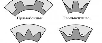
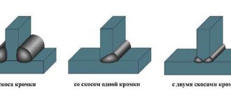
According to their shape, keys are divided into prismatic, segmental, wedge and tangential. The standards provide for different designs of keys: for example, prismatic keys with two rounded ends, with one rounded end, with non-rounded ends, full-shaped segmental keys and with a cut-off edge of the segment.
The most commonly used keys are parallel keys. They make it possible to obtain both movable and fixed connections. Key lengths
choose from the range: 6, 8, 10, 12, 14, 16, 18, 20, 22, 25, 28, 32, 40, 45, 50, 56, 63 and further up to 500 mm with a tolerance range. The length of the blind keyway has a tolerance range.
Values of maximum deviations of groove depths on the shaft
and in the bushing depending on the height of the key are given in table. 3.25, 3.26.
Along the height of the key, the mating provides for the formation of a nominal gap, for which the sum of the groove depths exceeds the height of the key.
To form fixed connections, segment and wedge keys can be used. The shape and dimensions of the sections of keys and grooves are standardized and selected depending on the diameter of the shaft, and the type of key connection is determined by the operating conditions of the connection.
Unlike shaft-bushing connections with tension, which ensure mutual immobility of parts without additional structural elements, keyed connections are detachable. They allow the structure to be disassembled and reassembled, providing the same effect as during the initial assembly (Fig. 3.107).
The figure shows that the key connection involves the creation of three fits: shaft-bushing (centering mate), key-shaft groove and key-groove of the bushing. In a keyed connection, another pairing is possible - along the length of the key, if a parallel key with rounded ends is placed in a blind (closed on both sides) groove on the shaft.
The accuracy of centering of parts in a keyed connection is ensured by the fit of the sleeve on the shaft. This is normal smooth
cylindrical mate, which can be assigned with very small gaps or interferences.
However, the correct design of the fit for this connection significantly affects the operating conditions of the keyway. To improve centering accuracy, it is preferable to use transitional fits or even fits with slight interference.
There are practically no mates in the height of prismatic and segment keys, since a nominal clearance is specially provided (the total depth of the grooves of the sleeve and shaft is greater than the height of the key). In wedge keyed joints, the height gap is usually selected by longitudinal movement of the key, but in this case the gap in the centering joint (if there is one) is also selected in one direction, which leads to a relative displacement of the shaft and hole axes.
Recommended tolerance ranges for shaft-bushing connections are given in table. 3.27.
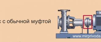
Keyed connections can be movable or fixed in the axial direction. A gear, gear block, half-coupling or other part usually moves along a shaft with a guide key (here the guide is a shaft with a key). In moving joints, guide keys are often used and are secured to the shaft with screws. Keys can also be attached to the sleeve and serve to transmit torque or to prevent rotation of the sleeve as it moves along a stationary shaft. Thus, a key attached to the bracket of a heavy rack for installing measuring heads such as microcators is designed to prevent the bracket from rotating when it moves longitudinally along the column of the rack. In this case, the guide is a column - a shaft with a keyway.
The performance of key joints is determined mainly by the accuracy of the fit along the width of the key b. The remaining dimensions are set in such a way as to facilitate the assembly process as much as possible while maintaining the necessary reliability of the connection. Tolerances of other elements in keyed connections are given in table. 3.28.
According to the mating size (width of the key and grooves of the shaft and bushing), there are three connection options for parallel keys: loose, normal and tight (Table 3.29).
The most widespread in general mechanical engineering is the normal connection; loose connection is used mainly for guide keys, sometimes in the presence of volumetric heat treatment; tight connection - in case of reverse or start-stop mode of shaft rotation.
To ensure the assembly of the keyed connection, the keyways of the shaft and bushing are subject to certain requirements for accuracy of location. Tolerances are established for the parallelism of the keyway relative to the axis of the corresponding step of the part and its symmetry. The parallelism tolerance is determined by relative geometric accuracy class A and is about 60% of the keyway width tolerance, and the symmetry tolerance, specified in diametrical terms, is approximately four keyway width tolerances:
Calculated values are rounded to standard values according to GOST 24643-81.
The roughness of the keyway surfaces is selected depending on the tolerance margins of the keyway dimensions
Symbols in the drawings
The symbol for parallel keys includes the following elements:
-the word “Spline”;
- designation of version (version 1 is not indicated);
- section dimensions and length of the key;
- designation of the standard.
An example of a symbol designation for a feather key, version 2, with dimensions
Key 2 - 4 x 4 x 12 GOST 23360-78.
An example of a symbol designation for a prismatic guide key design 3 with dimensions
Key 3 - 12 x 8 x 100 GOST 8790-79.
Segment keys are usually used to transmit small torques. The dimensions of segment keys and keyways (GOST 24071-80) are selected depending on the diameter of the shaft.
The types of tolerance fields for the width of grooves for segmental keyed connections depend on the nature of the keyed connection (Table 3.30).
For heat-treated parts, maximum deviations of the shaft groove width are allowed according to
, sleeve groove width (free type connection).
The standard establishes the following tolerance fields for key sizes:
- width ;
- heights;
- diameter
The symbol for segment keys includes the following elements:
- the word "Spline";
- execution designations (version 1 is not indicated);
- section dimensions
- designation of the standard.
An example of a symbol for a segment key of version 2 with dimensions
Key 2 - 4 x 6.5 GOST 24701-80.
Wedge keys are used in fixed keyed connections when the requirements for the alignment of the parts being connected are low. The dimensions of wedge keys and keyways are standardized by GOST 24068-80. The length of the groove on the shaft for the taper key of version 1 is made equal to
, for other versions the length of the groove is equal to the length of the key.
Maximum size deviations
for wedge keys are the same as for prismatic keys (GOST 23360-78).
Along the width of the key
the standard establishes connections along the width of the groove of the shaft and sleeve using tolerance fields. The length of the shaft groove is with the field. The maximum deviations of the groove depth I correspond to the deviations for parallel keys.
Limit deviations of the angle of inclination of the upper edge of the key and groove
according to GOST 8908-81.
Example of symbol designation for taper key version 2 with nominal dimensions
Key 2 - 8 x 7 x 25 GOST 24068-80.
Methods and means of monitoring elements of keyed joint parts
Two methods are used for control: differential (element-by-element) and complex. To implement the first method, universal measuring instruments are used. The choice of a particular measuring instrument is determined by the possibility of its use, taking into account the specific configuration of the part and ensuring the required measurement accuracy. It is advisable to use the method at the stage of debugging the technological process. It is highly informative, but requires a lot of time and certain qualifications of personnel. Comprehensive control of standardized keyways is used to control the suitability of finished parts and is carried out with gauges (Fig. 3.108). The width of the grooves of the shaft and bushing is checked with plates having a pass and a non-pass side (Fig. 3.108, a). Dimension from the generatrix of the cylindrical surface of the bushing to the bottom of the groove
control with a plug with a stepped protrusion (Fig. 3.108, b).
To directly monitor the deviation from the symmetry of the keyway deviation, gauges of two versions can be used (Fig. 3.109).
When inspecting a part according to option I, the gauge is inserted into the keyway. A shaft with a keyway is considered suitable if the protrusion of a special keyed prism gauge fits into the keyway and there is no gap between the shaft and the measuring surfaces of the prism gauge.
When inspecting a part according to option II, the gauge is inserted into the keyway and the part is considered valid if the gauge passes.
For comprehensive control of the dimensions and deviations in the location of the keyway, a key gauge-plug can be used (Fig. 3.110).
When inspecting a part, a key gauge-plug is inserted into the hole, and if the gauge passes into the part, it is considered that the first condition for the suitability of the part is met.
Measurements can also be performed using a special overhead measuring device (Fig. 3.111), consisting of two measuring heads fixedly mounted in an installation module rigidly connected to a control mandrel of a cylindrical or prismatic shape. This measuring instrument is pre-set to zero using a reference part that has the same configuration and nominal dimensions as the part being tested. When setting up and when performing measurements, the measuring instrument is based in such a way that the control mandrel fits tightly into the groove of the part (model or controlled). When measuring location deviations, the measuring instrument is moved in the direction of the axis of the part being tested along the groove and the maximum difference in the readings of the measuring heads along the length of the groove is recorded.
Half of the recorded maximum difference in the readings of the measuring heads is taken as the measurement result.
This lecture is taken from the lectures page on standardization of accuracy:
Standardization of accuracy: course of lectures
Perhaps these pages will help you:
| Accuracy standards for threaded parts and connections |
| Pin connections: designations and purpose |
| Spline connections |
| Interchangeability, methods for monitoring gears and gears |
Designations on the drawings
In the drawings, the designation of parallel keys is based on the GOST regulatory document. They are divided into keyways: high, normal height and guides. Their working faces are the lateral ones.
In the assembly drawing, the designation is made taking into account the shaft diameter, torque, cross-section and length.
For example:
Key 3–20Х12Х120 GOST 23360-78; Where 3 is the design, 20X12 is the section, 120 is the length.
Download GOST 23360-78
The designation of other types of keys in the images is carried out in the same way, based on the corresponding GOSTs developed for each individual model. The specified designation must clearly characterize the part, which is very important for obtaining a reliable connection. After all, even the slightest gap can cause rapid wear of working units and loss of efficiency during operation.
Advantages and disadvantages
Like any type of connection, keyed connections have a number of advantages and disadvantages. The advantages of keyed connections include the simplicity of most types of keys. At the same time, installation and replacement of such a part is easy and quick. Thanks to this, they are widely used in mechanical engineering. Also provides protection function.
Disadvantages include weakening of the hub and shaft. It arises from increased stress and reduced cross-section. Also, the weakening of parts is caused by the cut groove, which reduces the axial strength of the shaft.
To minimize the shortcomings, you need to ensure that the key is not skewed in the groove. To do this, you need to ensure that there is no gap, which is done by individually manufacturing and adjusting the key. Because of this, any type of keyed joints are rarely used in large-scale production. If it is not possible to ensure the absence of misalignment, the working contact area decreases, as a result of which the degree of maximum load decreases.
Also, the presence of a gap causes a runout effect, especially at high speeds. This will lead to rapid wear of working parts. Because of this, such a connection is rarely used for rapidly rotating shafts. To select a suitable key, it is better to use the table of key connections.
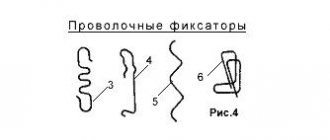
Friction key.
Rice.
3 A friction key (Fig. 3) is one of the types of wedge key. The design of the connection is clear from the drawing. In this connection, the load is transferred only by friction. Therefore, it can be used as a safety device during overloads. In addition, the friction key allows you to adjust the position of the hub on the shaft in both the angular and axial directions, which is also used in practice. When calculating the strength of a connection, they usually do not take into account the influence of changes in the shape of the initial stress diagram σ1 from the action of the friction torque (Nfh) applied to the key. In this case, having considered the equilibrium of the shaft, we obtain the condition for the strength of the connection in the form
σ1σ1≈400÷500 kgf/cm2
Key material
For the manufacture of keyed joints, calibrated rolled metal is used. The most commonly used steel is grade 45. It is a regular type of carbon steel, which is often used to produce high-strength parts. The steel is used in the form of a 1 m long bar.
In some cases, carbon steel grade 50 can be used. It is necessary when increased strength properties of the resulting keys are required. Less commonly used are alloy steels, for example, grade 40x, which is characterized by a high hardness index achieved by heat treatment.
Download GOST 8787-68
Steel blanks are processed using cutters, drilling machines, chopping machines, grinders and other tools. The machines used have a control unit that allows, using numerical programs, to produce a part with the required parameters.
The price of the resulting key is quite low, so purchasing the necessary part is quite easy. But in some cases, when there is an urgent need to obtain a key, you can make it yourself. Most often, such a need arises in agriculture, where during seasonal work breakdowns often occur that need to be repaired. At the same time, the nearest points of sale of the necessary parts are located at a distance of several tens of kilometers.
With a small amount of tools on hand and a blank made of the appropriate material, you can quickly make a temporary replacement. If the technical specifications are observed, the resulting part can fully replace the factory one, but it is best to purchase a key of the required strength and geometric parameters at the first opportunity. This is necessary to avoid premature wear of the mechanisms.
Sometimes other materials, such as high quality plastic, may be used for production. Wood can be used as a material, most often in the manufacture of furniture.
It is better to use different types of wood as a material; for a dowel, a softer material than the main one is suitable. This will protect the main structure from damage in case of increased load. It is easier to replace a key than a large structural unit.
To prevent moisture from penetrating into reinforced concrete structures, special dowels called waterstop are used. They are made from high quality rubber and PVC. This allows you to achieve the required degree of waterproofness and resistance to solutions of aggressive chemicals.
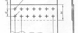
Mortise wedge keys.
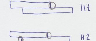
Mortise wedge keys (Fig. 1) are characterized by the following provisions:
- free fit of the hub on the shaft (with clearance);
- the location of the key in the groove with gaps along the side edges* (the wide edges of the key are the working ones);
- transmission of torque from the shaft to the hub mainly due to the friction forces that are formed in the connection from the pressing of the key.
∗ The need for these gaps is associated with the technological difficulties of fitting the key along all four faces.
Rice. 1
Pressing the key shifts the centers of the shaft and hub by a certain amount Δ (see Fig. 1), equal to half the fit gap and deformation of the parts. This displacement causes unbalance and adversely affects the operation of the mechanism at high rotation speeds.
The wedge shape of the key can cause skew of the part, in which its end plane will not be perpendicular to the shaft axis. Machining a groove in the hub with a slope equal to the slope of the key creates additional technological difficulties and often requires individual fitting of the key to the groove. Such a fit is completely unacceptable in mass production conditions.
These shortcomings have caused the use of wedge keys to sharply decline in modern production, which can ensure an accurate fit of the hub on the shaft without much difficulty. In the past, when it was difficult to ensure that the hub fits onto the shaft without large gaps, the taper key was a means of correcting manufacturing defects, since it selected the gap and created interference in the connection.
∗ A significant reduction in the use of wedge keys makes it possible not to consider all their varieties in this article and not to provide a detailed analysis of the stress state in the connection.
Even before the load is applied, stresses σ1 and σ2 are formed in the connection (see Fig. 1).
To solve the problem of connection strength, consider the equilibrium conditions of the shaft under load with moment T (Fig. 2). In the design scheme according to (Fig. 2), the action of stresses σ1 and σ2 (see Fig. 1) is replaced by the resultant N. The moment tends to rotate the shaft in the hub hole. This rotation is prevented by a pair of friction forces F=Nf and pinching of the key. When pinched, the left half of the key is additionally loaded, and the right half is unloaded. The stress diagram on the key faces is transformed from uniform to trapezoidal with maximum stress σ. The triangular diagram corresponding to the joint opening boundary on the right side of the key is taken as the calculated diagram, i.e., one in which the bearing stresses still extend over the entire width of the key, but at the right edge are already close to zero. In this case, the point of application of the resultant N is shifted from the central axis by the amount
σ
σ
Rice. 2
Currently, there is no data on the value of σ1 that can be obtained when pressing a key. Therefore, the calculation is made according to the last condition, in which [σcm] is established based on experience:
[σcm]=800÷1000 kgf/cm2. In this case, σ1≈400÷500 kgf/cm2. It is also recommended to take f≈0.13÷0.18.