It would seem that there is something complicated in the pipes? Connect and twist... But, if you are not a plumber or an engineer with a specialized education, then questions will definitely arise for answers to which you will have to go wherever you look. And most likely the first thing they look at is the Internet)
We have previously talked about the diameters of metal pipes in this material. Today we will try to clarify the threaded connections of pipes for various purposes. We tried not to clutter the article with definitions. The basic terminology is contained in GOST 11708-82, which everyone can familiarize themselves with.
Pipe cylindrical thread. GOST 6357 - 81
Parameter Unit: Inch
Direction: Left
Accuracy class: Class A (increased), Class B (normal)
Why in inches?
The inch size came to us from our Western colleagues, since the requirements of the GOST are formulated on the basis of BSW (British Standard Whitworth or Whitworth thread). Joseph Whitworth (1803 - 1887), a design engineer and inventor, demonstrated the screw profile of the same name for detachable connections back in 1841 and positioned it as a universal, reliable and convenient standard.
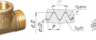
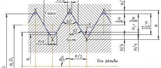
This type of thread is used both in the pipes themselves and in the elements of pipe connections: locknuts, couplings, elbows, tees ( see picture above
). In the profile section we see an isosceles triangle with an angle of 55 degrees and roundings at the tops and bottoms of the contour, which are made for high tightness of the connection.
Threading of threaded connections is carried out on sizes up to 6”. All larger pipes are fixed by welding to ensure a reliable connection and prevent rupture.
Symbol in the international standard
International: G
Japan: PF
UK: BSPP
The letter G and the bore diameter (internal Ø) of the pipe are indicated in inches. The outer diameter of the thread itself is not included in the designation.
Example:
G 1/2 - external cylindrical pipe thread, internal pipe Ø 1/2". The outer diameter of the pipe will be 20.995 mm, the number of steps over a length of 25.4 mm will be 14.
The accuracy class (A, B) and the direction of turns (LH) can also be indicated.
For example:
G 1 ½ - B - cylindrical pipe thread, internal Ø 1 ½ inches, accuracy class B.
G1 ½ LH- B - cylindrical pipe thread, internal Ø 1 ½ inches, accuracy class B, left.
The make-up length is indicated by the latter in mm: G 1 ½ -B-40 .
For internal pipe cylindrical threads, only the Ø of the pipe for which the hole is intended will be indicated.
Parallel Pipe Thread Size Chart
| Thread size | Thread pitch, mm | Threads per inch | Thread diameters | |||
| Row 1 | Row 2 | d=D | d2=D2 | d1=D1 | ||
| 1/16″ | 0,907 | 28 | 7,723 | 7,142 | 6,561 | |
| 1/8″ | 9,728 | 9,147 | 8,566 | |||
| 1/4″ | 1,337 | 19 | 13,157 | 12,301 | 11,445 | |
| 3/8″ | 16,662 | 15,806 | 14,950 | |||
| 1/2″ | 1,814 | 14 | 20,955 | 19,793 | 18,631 | |
| 5/8″ | 22,911 | 20,749 | 20,587 | |||
| 3/4″ | 26,441 | 25,279 | 24,117 | |||
| 7/8″ | 30,201 | 29.0З9 | 27,877 | |||
| 1″ | 2,309 | 11 | 33,249 | 31,770 | 30,291 | |
| 1⅛» | 37,891 | 36,418 | 34,939 | |||
| 1¼» | 41,910 | 40,431 | 38,952 | |||
| 1⅜» | 44,323 | 42,844 | 41,365 | |||
| 1½» | 47,803 | 46,324 | 44,845 | |||
| 1¾» | 53,746 | 52,267 | 50,788 | |||
| 2″ | 59,614 | 58,135 | 56,656 | |||
| 2¼» | 65,710 | 64,231 | 62,762 | |||
| 2½» | 75,184 | 73,705 | 72,226 | |||
| 2¾» | 81,534 | 80,055 | 78,576 | |||
| 3″ | 87,884 | 86,405 | 84,926 | |||
| 3¼» | 93,980 | 92,501 | 91,022 | |||
| 3½» | 100,330 | 98,851 | 97,372 | |||
| 3¾» | 106,680 | 105,201 | 103,722 | |||
| 4″ | 113,030 | 111,551 | 110,072 | |||
| 4½» | 125,730 | 124,251 | 122,772 | |||
| 5″ | 138,430 | 136,951 | 135,472 | |||
| 5½» | 151,130 | 148,651 | 148,172 | |||
| 6″ | 163,830 | 162,351 | 160,872 | |||
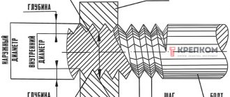
How to determine the pitch of an inch thread
I’ll give you a picture from the English-language Internet that clearly demonstrates the technique. Pipe threads are characterized not by the size between the tops of the profile, but by the number of turns per 1 inch along the thread axis. A regular tape measure or ruler can help. Apply it, measure one inch (25.4 mm) and visually count the number of steps.
In the picture with an example ( see above
) threads - from English these are literally “threads of thread”. In this case there are 18 of them. by one inch.
It’s even easier if you have a thread gauge for inch threads lying around in your tool box. It is very convenient to take measurements, but it must be remembered that inch threads may differ in the apex angle of 55° and 60°.
| Thread pitch P, mm | Threads per inch |
| 0.907 | 28 |
| 1,337 | 19 |
| 1,814 | 14 |
| 2,309 | 11 |
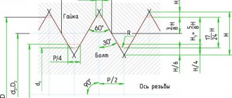
Types of pipe threads
So, what is pipe thread? This is the one that has grooves of a special profile. It is based on a triangle with a 55° vertex and rounded vertices. The symbol is G, after which the nominal diameter of the pipe is indicated in inches. That is, on the drawings they put G 1 1/2″. This will mean that the connection is threaded, a pipe thread with a nominal diameter of 1 1/2 inches.
How are pipe threads indicated on drawings? Letter G and numbers. The number is the nominal diameter of the pipe
Cylindrical pipe thread: features, designation, dimensions
Cylindrical pipe threads are described in GOST 6357-81. It is applied to the outside or inside of the pipe. The standard also allows for the connection of an outer conical and an inner cylindrical. In general, the thread must be made with curves, the radius of which is also specified. However, for connecting cylindrical parts, a straight cut of the vertices of the triangle is allowed (but not for connecting with conical threads).
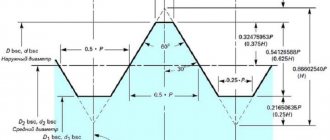
Parallel Pipe Thread Profile
Next are the sizes. Cylindrical pipe threads can be external or internal. They are characterized by three diameters: outer, inner and middle. And also the working height of the profile, rounding diameter and pitch. The diameters and number of turns are shown in the table.
| Thread size in inches | Turn pitch, mm | Number of turns per inch, pcs. | Diameter of pipe cylindrical thread, mm | |||
| Row 1 | Row 2 | D=d | D1 = d1 | D2 = d2 | ||
| 1/16 « | 0,907 | 28 | 7,723 | 7,142 | 6,561 | |
| 1/8″ | 9.728 | 9.147 | 8,566 | |||
| 1/4″ | 1,337 | 19 | 13,15 | 12,301 | 11,445 | |
| 3/8″ | 16,662 | 15,806 | 14,950 | |||
| 1/2″ | 1,814 | 14 | 20,955 | 19,793 | 18,631 | |
| 3/4″ | 22,911 | 21,749 | 20,587 | |||
| 5/8″ | 26,441 | 25,279 | 24,117 | |||
| 7/8″ | 30,201 | 29,039 | 27,877 | |||
| 1″ | 2,309 | 11 | 33,249 | 31,770 | 30,291 | |
| 1 1/8″ | 37,897 | 36,418 | 34,939 | |||
| 1 1/4″ | 41,910 | 40,431 | 38,952 | |||
| 1 3/8″ | 44,323 | 42,844 | 41,365 | |||
| 1 1/2 | 47,803 | 46,324 | 44,845 | |||
| 1 3/4″ | 53,746 | 52,267 | 50,788 | |||
| 2″ | 59,614 | 58,135 | 56,656 | |||
| 2 1/4″ | 65,710 | 64,231 | 62,752 | |||
| 2 1/2″ | 75,184 | 73,705 | 72,226 | |||
| 2 3/4″ | 81,534 | 80,055 | 78,576 | |||
| 3″ | 87,884 | 85,405 | 84,926 | |||
| 3 1/4″ | 93,980 | 92,501 | 91,022 | |||
| 3 1/2″ | 100,330 | 98,851 | 97,372 | |||
| 3 3/4″ | 106.680 | 105,201 | 103,722 | |||
| 4″ | 113.030 | 111.551 | 110.072 | |||
| 4 1/2″ | 125,730 | 124,251 | 122,772 | |||
| 5″ | 138,430 | 136,951 | 135,472 | |||
| 5 1/2″ | 151,130 | 149,561 | 148,172 | |||
| 6″ | 163,830 | 162,351 | 160,872 | |||
According to the table, there shouldn’t seem to be any questions. It is only worth mentioning that if you have a choice, you should choose sizes from row 1. The thread pitch and number of turns are the same for several pipe diameters. The missing parameters - the working height of the profile and the rounding diameters - are taken from the second table.
Working profile height and rounding diameters for cylindrical pipe threads
A cylindrical pipe thread is designated by the Latin letter G, followed by the nominal diameter of the pipe in inches. For example: G 1/2″, G 2″, etc. The following is indicated:
- If the thread is left-handed, the letters LH are put down, if the thread is right-handed, nothing is put in.
- Accuracy class - A or B (A has smaller permissible deviations) separated by a hyphen. For example, G 1 1/8″ - A or G 2″ LH - B. The second is a left-hand thread with accuracy class B.
- Then the make-up length is prescribed (the length of the section in millimeters on which the thread is applied). G 5/8″ - A - 40.
If a connection is described - a pipe/coupling, for example - the accuracy class is indicated for both parts. For example, G 2 3/4″ - A/A or G 1″ - B/A. First, the accuracy class of the pipe thread is indicated, then the coupling or installed device.
Tapered pipe thread: features, size table, designation
This type of threaded connections is used where high reliability of the connection is required. Tapered pipe threads are distinguished by the fact that they are applied to a cone. Its profile remains exactly the same, but two values are added - the working length of the thread l1 and l2 - the length from the end to the main plane. These columns are added to the table.
Tapered pipe thread: profile, main dimensions
| Thread size in inches | Turn pitch P, mm | Number of turns per inch, pcs. | Diameter of pipe conical thread, mm | Thread length, mm | |||
| D=d | D1 = d1 | D2 = d2 | l1 | l2 | |||
| 1/16 « | 0,907 | 28 | 7,723 | 7,142 | 6,561 | 6,5 | 4,0 |
| 1/8″ | 9.728 | 9.147 | 8,566 | ||||
| 1/4″ | 1,337 | 19 | 13,15 | 12,301 | 11,445 | 9,7 | 6,0 |
| 3/8″ | 16,662 | 15,806 | 14,950 | 10,1 | 6,4 | ||
| 1/2″ | 1,814 | 14 | 20,955 | 19,793 | 18,631 | 13,2 | 8,2 |
| 3/4″ | 26.441 | 25.279 | 24.117 | 14.5 | 9.5 | ||
| 1″ | 2,309 | 11 | 33,249 | 31,770 | 30,291 | 16.8 | 10.4 |
| 1 1/4″ | 41,910 | 40,431 | 38,952 | 19.1 | 12.7 | ||
| 1 1/2″ | 47,803 | 46,324 | 44,845 | 19.1 | 12.7 | ||
| 2″ | 59,614 | 58,135 | 56,656 | 23.4 | 15.9 | ||
| 2 1/2″ | 75,184 | 73,705 | 72,226 | 26.7 | 17.5 | ||
| 3″ | 87,884 | 85,405 | 84,926 | 29.8 | 20.6 | ||
| 3 1/2″ | 100,330 | 98,851 | 97,372 | 31.4 | 22.2 | ||
| 4″ | 113.030 | 111.551 | 110.072 | 35.8 | 25.4 | ||
| 5″ | 138,430 | 136,951 | 135,472 | 40,1 | 28,6 | ||
| 6″ | 163,830 | 162,351 | 160,872 | 40,1 | 28,6 | ||
A cylindrical thread is designated by the letter R with indices that indicate the type of surface:
- Simply R is for external tapered thread.
- Rc - conical internal.
- Rp - cylindrical internal.
After the letters, put the conventional pipe size in inches, then, if the application is left-handed, add LH. For example, R 3/4, R2 1/2 LH. When describing threaded connections, designations are written in the form of a fraction. Usually the numerator is external, the denominator is internal. For example, Rc/R 3/8.
Tapered pipe threads
drawing of pipe tapered threads
Tapered pipe thread GOST 6211-81 (1st standard size)
Parameter Unit: Inch
Fits a rounded 55° straight pipe thread profile. See the top part (I) of the 3D image "drawing of pipe tapered threads".
Symbol
International: R
Japan: PT
UK: BSPT
The letter R and the nominal diameter Dy are indicated. The designation R means external thread, Rc internal, Rp internal cylindrical. By analogy with cylindrical pipe threads, LH is used for left-hand threads.
Examples:
R1 ½ - external pipe thread, nominal diameter Dy = 1 ½ inches.
R1 ½ LH - external pipe thread conical, nominal diameter Dy = 1 ½ inches, left.
Conical inch thread GOST 6111 - 52 (2nd standard size)
Parameter Unit: Inch
Produced on surfaces with a taper of 1:16
Has a profile angle of 60°. See the bottom part (II) of the 3D image "drawing of pipe tapered threads". It is used in pipelines (fuel, water, air) of machines and machines with relatively low pressure. The use of this type of connection assumes tightness and locking of the thread without additional special means (linen threads, yarn with red lead).
Symbol
The first letter is K, then GOST.
Example:K ½ GOST 6111 - 52
It stands for: inch conical thread with an outer and inner diameter in the main plane approximately equal to the outer and inner Ø of a cylindrical pipe thread G ½
Table of main parameters of tapered inch threads
| Thread size designation (d, inches) | Number of threads per 1″ n | Thread pitch S, mm | Thread length, mm | Outer thread diameter in the main plane d, mm | |
| Working l1 | From the end of the pipe to the main plane l2 | ||||
| 1/16 | 27 | 0,941 | 6,5 | 4,064 | 7,895 |
| 1/8 | 27 | 0,941 | 7,0 | 4,572 | 10,272 |
| 1/4 | 18 | 1,411 | 9,5 | 5,080 | 13,572 |
| 3/8 | 18 | 1,411 | 10,5 | 6,096 | 17,055 |
| 1/2 | 14 | 1,814 | 13,5 | 8,128 | 21 793 |
| 3/4 | 14 | 1,814 | 14,0 | 8,611 | 26,568 |
| 1 | 11 1/2 | 2,209 | 17,5 | 10,160 | 33,228 |
| 1 1/4 | 11 1/2 | 2,209 | 18,0 | 10,668 | 41,985 |
| 1 1/2 | 11 1/2 | 2,209 | 18,5 | 10,668 | 48,054 |
| 2 | 11 1/2 | 2,209 | 19,0 | 11,074 | 60,092 |
NPT thread, tapered
(National pipe thread)
Tapered (NPT) 1:16 taper (3°34'48″ taper angle) or parallel (NPS) threads per ANSI/ASME B1.20.1. The profile angle at the apex is 60°, the theoretical profile height is Н=0.866025Р. NPT thread corresponds to GOST 6111-52 - Conical inch thread with a profile angle of 60 degrees. The standard provides thread sizes from 1/16″ to 24″ for pipes according to ANSI/ASME B36.10M, BS 1600, BS EN 10255 and ISO 65. Symbols: Typically the symbols used are “MNPT” for male threads and “FNPT” for internal, the numerical value of the nominal thread diameter in inches (inch). For example, an internal thread with a nominal diameter of 1/4″ is designated as: FNPT 1/4″. For more information about threads, thread pitch and other parameters, see the website
Metric tapered thread. GOST 25229 - 82
Parameter unit: mm
Produced on surfaces with a taper of 1:16
Used when connecting pipelines. The angle at the top of the turn is 60°. The main plane is shifted relative to the end ( see figure above
).
Symbol
The letters MK are followed by an indication of the diameter in the main plane and the thread pitch in mm: MK 30x2
Metric Tapered Thread Size Chart
| Thread diameter d for row | Step P | Thread diameter in the main plane | ||||||
| 1 | 2 | d = D | d2=D2 | d1=D1 | l | l1 | l2 | |
| 6 | — | 1 | 6,000 | 5,350 | 4,917 | 8 | 2,5 | 3 |
| 8 | — | 8,000 | 7,350 | 6,917 | ||||
| 10 | — | 10,000 | 9,350 | 8,917 | ||||
| 12 | — | 1,5 | 12,000 | 11,026 | 10,376 | 11 | 3,5 | 4 |
| — | 14 | 14,000 | 13,026 | 12,376 | ||||
| 16 | — | 16,000 | 15,026 | 14,376 | ||||
| — | 18 | 18,000 | 17,026 | 16,376 | ||||
| 20 | — | 20,000 | 19,026 | 18,376 | ||||
| — | 22 | 22,000 | 21,026 | 20,376 | ||||
| 24 | — | 24,000 | 23,026 | 22,376 | ||||
| — | 27 | 2 | 27,000 | 25,701 | 24,835 | 16 | 5 | 6 |
| 30 | — | 30,000 | 28,701 | 27,835 | ||||
| — | 33 | 33,000 | 31,701 | 30,835 | ||||
| 36 | — | 36,000 | 34,701 | 33,835 | ||||