Methodology for calculating cutting conditions during turning
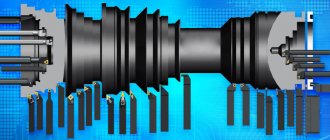
At the first stage, the material of the cutting part of the tool is selected, the type and design of the cutter, the geometry of the cutting part, that is, the angles of the cutting part (depending on the type of processing and the material of the workpiece)
Definition of cutting mode elements
1. Setting the cutting depth t
Allowance for processing is determined by the formula, mm:
,
where: D
3 - diameter of the workpiece surface being machined, mm,
D
- part diameter along the machined surface, mm. If the allowance is removed in one pass, then the cutting depth, mm:
If processing is divided into roughing and finishing, then:
2. Feed selection S
Feed S
is selected depending on the designated cutting depth
t
and a number of restrictions. The following restrictions apply to the feed amount:
During rough turning: strength and rigidity of the cutter holder; strength of the carbide plate and weak links of the machine feed mechanism; the rigidity of the workpiece and the method of its fastening. Formally, these restrictions are taken into account as follows.
When roughing external turning with cutters with inserts made of carbide and high-speed steel, the feed is selected depending on the selected cutting depth t
and taking into account the diameter of the part and the size of the cutter holder according to the tables (see appendix). The feeds allowed by the strength of the hard alloy plate during turning are selected from the tables (see appendix). You need to choose the smaller of the two - Smin. Select the nearest smaller feed from the machine data sheet for it.
In finishing and semi-finish turning, the following limitations may be: the specified roughness of the machined surface and the accuracy of the part; rigidity of the cutter holder and the workpiece. Depending on D
3types and processing conditions of the part material, and then checked for accuracy and rigidity.
3. Calculation of cutting speed V
Permissible cutting speed VT
calculated depending on the assigned values of cutting depth
t
, feed
S
and tool life
T
, m/min:
,
where: CV
– coefficient depending on the material being processed, type of work and cut thickness;
m, x, yv
– exponents for the values of tool life
T
, depth of cut
t
and feed
S
are determined from reference data (see appendix);
In a number of sources, exponents are given with the designation m, xv, yv
;
Kv
- the general correction factor for cutting speed is calculated as the product of partial correction factors, each of which reflects the difference between the actual value of one of the specific cutting conditions and the coefficient
C
V used in the experimental determination of the tabulated values:
, (1.21)
where: KMV
– correction factor for the physical and mechanical properties of the material being processed (see appendices);
KP
– correction factor for the state of the workpiece surface (see appendix);
CI
– correction factor for the brand of instrumental material (see appendix);
K
φ – correction factor for the magnitude of the main angle in plan (see appendix);
Kφ1
,
Kr
- correction factors for the auxiliary lead angle, the radius at the tip of the cutter and the cross-section of the cutter holder, included in the calculation only for cutters made of high-speed steel (see appendix);
Having determined K
v by formula (1.21),
VT
by formula (1.22) and using the cutting speed formula, you should determine the number of spindle revolutions
n
corresponding to the calculated value of the permissible cutting speed, rpm:
, (1.22)
The calculated value of the number of revolutions per minute should be adjusted, bringing it into line with the nearest lower value of the number of revolutions per minute of the machine spindle from its passport data.
The actual cutting speed can be calculated based on the selected spindle rpm n
st, m/min:
,
Since usually the actual cutting speed V
F is less than the calculated one, the actual tool life increases according to formula (1.21).
If the calculated number of revolutions per minute of the spindle is only 5...10% less than the nearest level of revolutions per minute of the machine available on the machine, you can use this step, and the actual tool life will decrease slightly.
Stage II. Check calculation of selected values of cutting mode elements
For verification calculations, it is necessary to calculate the cutting forces, in particular, the tangential force according to the formula
, (1.23)
where: Wed
– coefficient characterizing the group of processed materials (see appendix);
x, y, n
- exponents for depth of cut
t
, feed
s
and cutting speed
v
are determined from tables (see appendix);
Kr
– correction factor, calculated as the product of correction factors by the mechanical properties of the material being processed and the geometric parameters of the cutter;
, (1.24)
The values of correction factors in formula (1.24) should be selected according to reference data (see appendix)
1. Checking the selected feed rate s based on the strength of the holder
cutter is performed only during rough turning.
Based on the fact that the cutter holder is subject to bending under the influence of force P
z, for a cutter with a rectangular cross-section we can write:
, (1.25)
where in
– holder width, mm;
H
– holder height, mm;
L
– cutter overhang,
l
=(1.5….2)
N
, mm;
[ σИ
] – permissible bending stress, MPa;
[ σИ
]=200 MPa.
If we substitute the expression Pz from (1.23) into (1.25), then we can determine the feed allowed by the strength of the cutter holder, mm/rev:
, (1.26)
2. Checking the selected feed rate based on the rigidity of the cutter holder
is produced in cases where the cutter must work with a significant overhang (for example, when boring relatively deep holes), under difficult processing conditions (for example, when the tip of the cutter moves towards the axis of the workpiece during cutting), as well as during finishing turning.
The maximum load allowed by the rigidity of a part depends on the method of its fastening, for example, in a chuck:
, (1.27)
where: E
– modulus of elasticity of the part material, Pa (for carbon structural steel E = 200000 ... 220000 Pa);
I
– moment of inertia of the holder;
f
additional – permissible deflection, mm (allowed for rough turning;
f
additional = 0.1 mm, for finishing 0.05 mm)
Substituting the expression for the cutting force from formula (1.23) into formula (1.27), we obtain an expression for the maximum feed allowed by the rigidity of the material, mm/rev:
, (1.28)
This is the calculated feed value S
f must satisfy the relation
S
f ≤
S
st, where
S
st was defined earlier.
3. Checking the selected feed rate using the kinematic data of the machine.
The following ratio must always be maintained:
S
min≤
S
st≤
S
max
where: S
max and
S
min are the largest and smallest feed values according to the machine’s passport data.
S assigned at the second stage of calculation
was adjusted in accordance with the machine's passport data. Therefore, if the following relations are met:
S
st≤
S
pr,
S
st≤
S
f
then checking the feed using the kinematic data of the machine should not be carried out.
4. Verification calculation for spindle power Ne.
The cutting power is determined by the cutting force
P
z and the actual value of the cutting speed
v
.
The cutting power should not exceed the effective power of the machine N
e, i.e. the ratio must be maintained
N
res≤
N
e, (1.29)
where: N
cut – cutting power, kW;
N
e =
Nη
– effective power of the machine, kW;
N
– power of the machine’s electric motor, kW;
η
– efficiency of the machine.
,
If relation (1.29) does not hold, one should substitute N·η
, determine the highest cutting speed allowed by the power of the machine.
However, it should be borne in mind that when the cutting speed decreases, P
z (1.23).
Therefore, it is necessary to recalculate P
z, and then, after checking the sufficiency of power, adjust the number of spindle revolutions per minute
n
N corresponding to
v
N the machine’s passport data.
The ultimate goal is to calculate the main technological (machine) time T
O.
It must be performed after checking the selected elements of the cutting mode. As stated earlier, it is the minimization of the main time T
o that is the goal of calculating the optimal cutting mode.
The main (machine) technological time should be calculated using the formula, min:
,
where: L
=
l
+
l
1+
l
2 — design processing length, mm;
l
is the length of the treated surface, mm;
l
1 - cutter penetration, determined from the ratio, mm:
mm
where: l
2 — cutter overtravel,
l
2 =1....5mm;
i
is the number of passes.
Labor productivity at any operation of the technological process of processing parts is determined by the value of piece time Tsht
, spent to perform the operation.
The amount of piece time is determined from the ratio, min:
where: That -
basic (machine) technological time;
Tvsp
- auxiliary time spent on installing, securing and removing the workpiece, on controlling the machine;
Tobsl -
time for organizational and technical maintenance of the workplace;
Toshd -
time to rest.
The assigned cutting modes directly or indirectly affect all components of piece time. Elements of cutting modes have a direct influence on the main (machine) time T0. Elements of cutting modes have an indirect effect on the remaining structural components of piece time, through a change in tool life T.
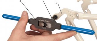
Tapping threads
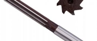
When cutting a thread with a tap, as with any other type of processing, it is necessary to take into account the grade of the workpiece material, the design of the tool, the capabilities of the machine, as well as the cutting conditions.
It is necessary to add to the above that when cutting threads, the load on the tooth of the tap far exceeds the load on the tooth of almost any other tool due to the constant contact of the tap with the side surface of the thread.
During the thread cutting process, it is necessary to ensure good chip removal to avoid breakage of the tap and to ensure high accuracy and good surface quality of the thread. All this creates additional difficulties for designers of metal-cutting tools in the struggle to increase productivity, durability and stability of processing.
Different taps for different materials
When designing taps for different materials, the rake angle and curvature of the rake surfaces of the tap are usually changed. For difficult-to-cut materials, these parameters have negative or zero values to ensure cutting edge strength. In addition, due to the large curvature of the front surfaces of the tap, when processing such materials, scoring may appear on the threads. When processing materials that produce continuous chips, taps with positive rake angles and a sufficiently large curvature of the rake surfaces are used, due to which the chips curl and break.
Another significant parameter of tap geometry is the clearance angle. For harder materials, high clearance taps are used to reduce friction and allow coolant to reach the cutting zone. But too much clearance reduces the ability of the tap to self-center. When machining ductile materials, too large a relief angle can lead to thread parameters outside the tolerance range.
Taps for cutting threads in blind holes differ from each other in the helix angle. For materials with higher strength, taps with a smaller helix angle are used. This ensures higher strength of the tap itself. For difficult-to-cut materials, taps with a short cutting length are also used to reduce cutting forces.
If you want to improve your threading efficiency, you need to pay attention to more than just the tool. For example, when cutting threads in gray cast iron with taps of the old design, you can process at a cutting speed of 10-15 m/min, and with taps of the new design - 75 m/min.
But it must be remembered that such a cutting speed is achievable only under certain conditions. For example, in the absence of an internal coolant supply, the cutting speed will need to be reduced to 45 m/min, since when high-speed steel overheats, its durability is greatly reduced.
When processing small threads, the spindle rotation speed may not be enough, and when processing large threads, the power of the equipment, and so on.
In addition to the geometry of the tap, the coating applied to the surface of the tool material is of great importance. Many coatings are used: TiN, TiCN, CrN, TiAlN. Thanks to the use of coatings, tool life increases and reserves appear to increase productivity.
Carbide taps
Just as carbide tools have gradually replaced high-speed steel tools in turning, carbide taps are becoming more and more used in thread cutting.
Due to their fragility, carbide taps are difficult to withstand heavy loads, unlike taps made of high-speed steel. Despite this, they have proven themselves to be excellent when processing materials such as gray cast iron and aluminum with a high silicon content, because when processing these materials, the main wear mechanism is abrasive.
The development of fine-grained carbide alloys with increased strength has led to the development of carbide taps with high strength and wear resistance. They can also be used when processing hardened steel, plastics and heat-resistant alloys. Carbide taps are becoming especially widespread with the development of metal-cutting equipment.
Rigid threading
Increasing processing productivity and product quality requires the use of appropriate equipment. Two groups of machines are widely used for thread cutting.
The first group is machines for drilling small holes and cutting threads in them; the spindle speed can reach 6000 min-1.
The second group is machining centers, which are now cutting more and more threads. On machines of this type, so-called rigid threading cycles are used (the spindle speed is synchronized with movement along the Z axis). These machines do not require the use of floating tap chucks. Thread cutting can be carried out at 2000-3000 min-1.
Machining centers are usually equipped with several functions useful for threading, such as faster removal of the tap from the hole and setting a limiting torque during threading, which helps prevent breakage of the tap.
Theoretically, when processing threads on machining centers, there is no need to use any means to compensate for the discrepancy between the tap pitch and the actual feed along the Z axis and the spindle speed. In fact, to compensate for the accumulated error during thread cutting, it is recommended to use SynchroFlex type tapping chucks with a built-in flexible element. Cartridges of this type have a compensation capacity of about 0.5 mm.
