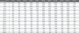
Hole depth and width
When assembling furniture, confirmat size 6.4*50 is usually used. Because the thread diameter is 6.4 mm, and the diameter of the confirmation body is 4.4 mm, then for high-quality fastening of parts, the hole diameter must be in the range of 4.5-5 mm and a depth of at least 50 mm.
If the thickness of the hole is greater than the specified one, the confirmat will not hold the parts well; if it is less, its thickness can tear the chipboard.
For drilling, use a confirmat drill with a diameter of 4.5 mm, which is equipped with an additional head for drilling an enlarged hole for the neck of the confirmat, which also makes a countersink for its head.
Of course, you can use a regular drill with a diameter of 5 mm, but for high-quality fastening in the hole you will additionally need to make space for the neck of the confirmat and its head.
Design features and types
A jig, in essence, is a template for drilling holes, allowing you to make them as accurately as possible. It is used both to create holes, the axis of which is perpendicular to the surface of the part, and for drilling at an angle.
Due to their versatility and simplicity, drilling jigs are widely used in various fields. In particular, in the mechanical engineering industry they have long been used to successfully drill holes in workpieces of various configurations and made of different materials. You cannot work without a conductor in furniture production, where such a device is actively used when assembling furniture, installing accessories on it and performing a number of other technological operations. Construction is another area where conductors are widely used. They are used, in particular, to drill holes in building structures. Conductors are also needed for drilling pipes and solving other tasks.
Even a simple device in the form of a strip with a stop greatly facilitates and speeds up the process of making holes of the same type
As furniture jigs, overhead models made of lightweight materials are most often used to make them more convenient to manipulate. You can purchase such devices prefabricated or make a furniture jig with your own hands. Qualified furniture makers may not use a jig to accurately and accurately drill holes in furniture structural elements, but to do this they must have extensive experience in their field.
The most significant advantage of the jig is that with its help, even a person who is not highly qualified can perform high-quality and accurate drilling of both a hole perpendicular to the surface of the part and an inclined hole. The use of jigs eliminates the need for complex preliminary calculations and marking the locations of future holes, which reduces the labor intensity of assembling a furniture structure and allows such work to be completed in a shorter period of time. Even a novice specialist can understand the use of a jig for drilling for dowels and solving other technological problems.
An overhead jig with a turret head is suitable for drilling standard holes for dowels of any size
Before purchasing or making your own homemade jig, determine what tasks you need to use it for, and based on this data, select its type and design.
Invoices
These jigs are so called because they are placed on the workpiece and secured to it or simply fixed by hand. Using jigs of this type, in particular, they drill holes in chipboard, MDF boards and other flat parts.
Rotary
Such templates can be used to make holes on cylindrical parts. Conductors of this type are equipped with vertical and horizontal axes of rotation, which makes it possible to make holes at different angles with their help.
Universal
These are devices that are especially relevant for small batch production, where the ability to quickly change over the equipment used is important. This type of conductor is endowed with just such functions.
This universal jig is designed for drilling holes for minifix, confirmat, rafix and door hinge
Tiltable
These devices for drilling holes are required in cases where such a technological operation has to be performed in several planes.
Sliding and pinning
The sliding jig, in full accordance with its name, does not require fastening: it is simply applied to the area of the surface of the part where the hole needs to be drilled. Fixed jig devices, although more convenient, somewhat limit the freedom of action of the specialist, which is especially critical when performing drilling work on machines equipped with only one spindle.
Marking drilling locations
In order to perfectly fasten two parts, it is necessary to mark the places of their fastenings as accurately as possible.
On the part that will be applied to the end (the one on which there will be a through hole), you need to make two measurements - along the length (usually 5-10 cm) and from the edge - exactly 8 mm (this is if the thickness of the plate is 16 mm).
On a part that lies perpendicular, mark the drilling point at the end. Here you need to maintain the same distance in length (5-10 cm from the beginning), and in width - strictly in the center (8 mm from the edge).
Markings must be done as accurately as possible, especially along the length, because If the markings are incorrect, your parts may have extra gaps or protrusions when joined.
It is better to make a through hole in the first part, attach it to the second - and immediately use a drill to mark the drilling location at the end of the second part. And then, separately, calmly drill the hole.
Drilling in two parts at the same time
This option is considered the most accurate and, moreover, the fastest. But in order to make a hole in two parts at the same time, you will need to fix them before drilling. To do this, you may need special clamps, clamps and other devices.
Hole Drilling Tools
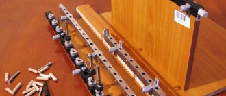
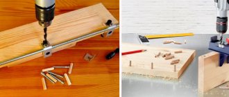
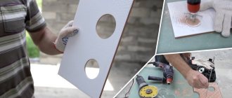
In order not to mark 8 mm from the edge each time both into the layer and at the end, you can use a special device, which, by the way, is easy to make yourself.
It is a kind of wooden template with a metal sleeve for a drill inside.
It looks like this, see photo:
And this is a more professional thing:
Watch a short video on how to accurately drill holes in chipboard for confirmations and assemble furniture parts:
Drilling into the layer of a part
We make a hole at a distance of 8 mm from the edge.
The drill should ALWAYS be held strictly perpendicular to the surface.
Before making a through hole, place a piece of unnecessary chipboard under the part. This will prevent chips from appearing on the reverse side.
When the through hole is made, the part can be drilled on the fly to drill holes for the neck and head of the confirmat.
Communities › DIY › Blog › device for drilling holes in furniture
I'm not a furniture maker, but I had to redo the cabinet, took the old one apart, ordered new sides and assembled it at home for confirmation. To make the holes even and accurate, I came up with such a device from waste. At first I made only a vertical hole, but then I made a horizontal one strictly to size. It’s convenient to drill along the edges - you don’t need to make markings, just move it close to the edge with a strobing pin and clamp it, and mark the middle hole. Since the holes were accurate and I made three times less markings for them, the cabinet became faster and lighter. I think maybe my idea will be useful to someone. More photos in the blog.
Drilling holes for confirmation
Modern furniture made of chipboard and MDF is often assembled using confirmatory screws, which among furniture makers are also called Euroscrews or Euroscrews. Before screwing them in, technological holes with strictly specified parameters are drilled in the plates. The process of preparing these holes will be discussed in this article.
The hole for the confirmation is drilled in the thickness of the first part and in the end of the second part, which are joined at a right angle. Along the length it should have a stepped difference in diameters. This is due to the design features of the Euroscrew. Its rod consists of a cylindrical smooth neck and a main threaded part. A hole of a smaller diameter is drilled for the thread, and a larger one for the neck. The fastener also has a countersunk head in the shape of a truncated cone, for which a seat is prepared. In practice, two hole drilling technologies are used.
Marking devices
Based on the difficulties of performing spatial markings, many tools and devices have been developed for its application. Moreover, most of these tools are suitable for application and planar marking.
Among the most common devices for spatial marking are:
- A scriber is the simplest and most versatile tool that does not require special training and allows you to apply markings in the field. Most often, it is a metal rod, one end of which is pointed. Typically, carbon steels of various grades are used for their manufacture. Either one or two ends can be sharpened, depending on the purpose of the tool. Their length is usually about 10 cm. Often, in order to prevent the end from becoming dull, it can be additionally hardened. Sketchers are usually used with rulers or templates.
- Reismas - the basis of the reismas is the devil, but it has a more complex design, as it is used for applying strokes on a vertical surface. It usually consists of a vertical post with metric markings applied, and a parallel post with a fixed scriber. This tool is used when it is necessary to apply high-precision markings.
- A compass is an indispensable tool necessary for drawing circles, arcs, as well as dividing segments into separate equal parts. There are two types: simple and spring. Simple ones will allow you to fix the legs in a certain position, measuring and selecting segments of the required length. Spring compasses are less common, but more accurate. Also highlight such a variety as marking calipers.
- A center punch is a metalworking tool in the form of a rod. It is used to make core recesses necessary for dividing circles into equal parts. One of its sides is pointed, a hole is made with it, and the other is flat, on which a blow is made with a hammer. The resulting hole makes working with the drill easier; it does not slip and is located exactly in the center.
The punch is usually made of partially hardened high-strength steel. The sharpened rod is subjected to hardening. Such a tool usually has a size from 10 to 18 cm.
You don't need to hit it with a hammer to make a hole. The most common of these is electric. It is based on a coil with a rod inside. When you press the tip, the circuit closes, a magnetic field appears in the coil, under the influence of which the rod hits the surface, creating a depression.
- A marking plate is a cast iron surface on which parts and tools for marking are installed. It should not lose shape, bend or bend during operation. Grooves can be made on the slab, forming equal squares. These grooves make it easier to install tools. Can be produced together with a stand or installed on a desktop.
- Prism – is a stand with a prismatic recess. It consists of two prism-shaped cheeks, between which the workpiece is installed. Can be installed on a screw support. With its help, you can adjust the position of the cheeks, increasing or decreasing the distance between them.
- Square with a shelf - most often used for planar markings, but can also be used for spatial markings. It is used in cases where there is a need for a precise positioning of the workpiece in the marking device.
- Marking wedges - used to adjust the installation height of an object with minimal deviations.
- Jacks are analogues of wedges, and also allow you to accurately adjust the height. The jack must be used in cases where the work involves massive workpieces.
Paint is used as an additional device for marking work. The surface is covered with it so that the marking strokes are clearly visible. It is selected in such a way that it contrasts well with the natural surface, even in dim lighting.
Using three drills of different diameters
Confirm screw made of galvanized steel
This method is suitable for small volumes of work, as it requires more time. Hole preparation is performed in three approaches:
First step
– drilling through two parts for the entire length of the Euroscrew. The diameter of the drill must be equal to the diameter of the screw body without taking into account the thread. This is done so that the threads can cut a counter thread in the material.
Second step
– expansion of the already obtained hole for the smooth part of the hardware, which should have a tight fit, but not too tight, so as not to split the material. Reaming is performed with a drill equal to the thickness of the neck and to a depth equal to its length.
Third step
– countersinking a hole to deepen the head into the material. This can be done with a drill of a larger diameter, but to obtain a high-quality result without chipping, it is better to perform this operation with a countersink.
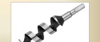
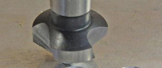
Confirmation drill – three in one
Working with a special confirmat drill (cutter) is much easier, since it has a special stepped geometry, and the entire operation is performed in one pass. An additional advantage of using it is that it simultaneously chamfers the countersunk head of the hardware. In fact, it replaces two drills and a countersink of different diameters. In addition, the confirmatory cutter has an insertion part with a sharp tip, which ensures precise insertion of the tool and eliminates the risk of it being pulled to the side at the beginning of drilling.
§ 11. General concepts
Blanks for machine parts are received for processing in mechanical and metalwork shops in the form of forgings of high-quality metal. Depending on the purpose of the parts, some workpieces remain unprocessed, others are processed partially or completely. When processing, a certain layer of metal is removed from the surface of the workpiece, as a result its size decreases. The difference between the size of the workpiece before and after processing is the value of the processing allowance.
To know where and to what size to process, the workpiece is first marked. Marking is the operation of applying marking lines (scores) to the workpiece being processed, defining the contours of the future part or the area to be processed.
Marking is carried out accurately and carefully, because errors made during marking can lead to the fact that the manufactured part turns out to be defective. It may also be the other way around: an inaccurately cast and therefore rejected workpiece can be corrected by careful marking, redistributing the allowances for each marked surface.
The accuracy achieved with conventional marking methods is approximately 0.5 mm. With precise marking, it can be increased to hundredths of a millimeter.
Marking is used mainly in individual and small-scale production. In large-scale and mass production factories, the need for markings is eliminated due to the use of special devices - jigs, stops, etc.
Types of marking are divided into three main groups: mechanical engineering, construction, boiler room and ship. Mechanical marking is the most common metalworking operation. Boiler room and ship markings have some peculiarities, and special literature is devoted to them.
Depending on the shape of the blanks and parts to be marked, marking is divided into planar and spatial (volumetric).
Planar marking is usually carried out on the surfaces of flat parts, on strip and sheet material, and consists of applying contour parallel and perpendicular lines (marks), circles, arcs, angles, axial lines, various geometric shapes according to given dimensions or contours of various holes according to specified dimensions to the workpiece. templates.
Using planar marking techniques, it is impossible to mark even the simplest body if its surfaces are not straight. When marking planarly, it is impossible to apply horizontal marks on the side surface of the cylinder, perpendicular to its axis, since it is impossible to attach a square and a ruler to it. But even if there were a flexible ruler that could be wound around the surface of the cylinder, then applying parallel marks to the cylinder would present great difficulties.
Spatial marking, the most common in mechanical engineering, differs significantly in techniques from planar marking. The difficulty of spatial marking lies in the fact that it is necessary not only to mark individual surfaces of a part located in different planes and at different angles to each other, but to link the markings of these individual surfaces with each other.
details on the website globalcolors.ru production of masterbatches. SMS notifications in Izhevsk are on our website. cutting pipes at an angle mnitek.ru/rezka-trub-i-profilya-pod-uglom/
Dimensions of holes for confirmation
There are no GOST standards for confirmed screws; they are manufactured according to European standards 3E120 and 3E122 and have a fairly wide size range, represented by the following standard sizes: 5x40, 5x50, 6.2x50, 6.4x50, 7x40, 7x48, 7x50, 7x60, 7x70 mm.
The most common size is 6.4x50 mm
. To drill a hole for its thread, a drill with a diameter of 4.5 mm is used, and for the smooth part - 7.0 mm.
When working with euroscrews of other sizes, the following rule is adhered to: the diameter of the main hole (for the thread) must be equal to the diameter of the rod without taking into account the height of the thread. That is:
- 5 mm screw – 3.5 mm drill
- 7 mm screw – 5.0 mm drill
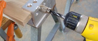
In order to prevent the risk of parts moving during drilling, it is necessary to firmly fix their position relative to each other. The easiest way to do this is with a corner clamp or other clamps.
Hello! We bought furniture produced by IOOO “BRV-BREST” During assembly, it turned out that the holes for the confirmations were 7mm. They were not 5mm clear. and f5.9 and they do not tighten the parts (sidewalls of the cabinets) but are welded. There are 20 such parts in total. In response to the complaint, the factory responded that: “the dimensions of the holes on the furniture parts, as well as the confirmations used for installation from the KENTAKI furniture set, displayed on the photographic material, correspond to the normative ones that were included in the design documentation at the design stage.” If there is no GOST for connection under confirmations, then I won’t prove anything and there’s no point in suing? Thank you if you answer.
Cookie Policy
Carrying out work on marking holes
Purchasing drilling equipment and high-quality cutting tools and cutting fluid is not yet enough to carry out work on drilling holes in metal. Accurate hole marking is one of the main tasks in this process.
According to calculations adopted during the USSR according to ENiR 40.2. The qualifications of specialists and the cost of work on marking natural templates or individual parts were much higher than the qualifications and cost of the work itself on drilling holes in metal.
The category of workers performing markings was composed of level 5, 1 person, and level 3, 1 person.
Performing drilling, which included the following operations: 1. Feeding parts to the machine. 2. Drilling holes with moving and edging the part.
3. Removing parts from the machine and stacking them. 1 or two people with 2nd category qualifications.
To perform marking work, a specialist must be able to read drawings, have knowledge of metalworking, and be responsible.
Currently using modern portable drilling machines with magnetic bases, spring punches and centralizers for annular cutters and core drills. As well as modern methods for making steel templates with preparation in AutoCOD DXF and precise laser cutting. It is possible to simplify the tasks of precise marking.
To drill holes in metal using annular cutters or core drills, a centralizer is installed inside the cutting tool. Made of tool steel, cylindrical, diameter 6.34 or 7.62 mm. with a sharp end on one side and a flat head on the other. The length of this tool corresponds to the length of the working part of the cutting tool.
The sharp end of the centralizer extending from the cutting tool marks the center of the hole at a precise point. To mark this point, use a spring, hand punch or thin marker.
A spring, manual punch, unlike a regular (non-spring) punch, is a more suitable and convenient tool due to the fact that to punch the center of a hole with a regular punch, you need to set it to a point and hit it with a hammer. Of course, in addition to physical effort, you need to have the hammer itself, two hands and room to swing nearby, which is not always available. It is also possible for the punch to jump off at the moment of impact or simply injury to the hand with a hammer.
A center punch, equipped with a spring mechanism, is installed with one hand at the center of the hole and, by pressing, sets in motion a movable striker made of tool steel, which performs the marking, while the impact force of the striker can be adjusted, which is important when working with soft or brittle materials. Separately, it is worth noting that the marks obtained using such a center punch have the same depth, which is important when drilling high-precision parts.
Of course, when using a spring punch, the speed of marking itself increases.
Also, the sharp and thin tip of the spring center punch, together with its pen-like shape, can be used to apply marking marks on a metal surface.
Although it happened that some workers, unfamiliar with such a modern device, used a hammer to perform core punching with a spring punch. At the same time, they were very surprised that the sharp tip of the core was springy and because of this they tried to strike sharper and stronger. Of course, the instrument could not withstand it for long and eventually failed.
When drilling a blind hole in metal using a twist drill bit. The transverse edge of a drill with a diameter of more than 16 mm (located at the very tip) cannot always fit into the dent marked with a center punch due to its width. Therefore, to perform accurate drilling with a twist drill, it is necessary to first drop the drill with a thin drill with a diameter of 3 mm. or more depending on the stated accuracy. Only then drill with a larger diameter drill.
For the convenience of marking and drilling blind holes with twist drills in metals, steels or cast iron on machines equipped with a Morse taper spindle connector, you can use an annular cutter or a core drill with an installed centralizer for marking. Using a centralizer, you can most accurately achieve the installation of a magnetic drilling machine. Especially when drilling holes in horizontal or vertical positions. After installing and aligning the centralizer to the mark, drilling is performed to a depth of 10-20 mm. After this, without removing the machine, the KM/Weldon drill chuck is removed and a twist drill with a KM shank is installed in the socket. The magnetic drilling machine, after pre-drilling, is positioned exactly in the center and the twist drill, also exactly in the center, performs the drilling.
If the holes are located in a group or in a circle (as on flange connections), one after another, a template must be used to mark the center of the hole. The template design is carried out in a three-dimensional computer-aided design and drawing system, AutoCAD DXF, and is produced on a laser cutting machine. It is of course possible to make a template using hand markings and hand tools. In this case, it is worth paying attention to the thickness of the manufactured template. If the marking template is made very thin 1-1.5 mm. You may encounter the fact that on an uneven metal surface, the template will bend and the alignment of the holes will be disrupted. An even thin template will turn out to be light and will easily move and disturb the alignment. If you make a template with a thickness of 5 mm or more. Then, in addition to the fact that the template will turn out to be heavy, the thickness in the places of the centering holes will not make it possible to punch exactly in the center or mark the marking point. The optimal template thickness is 2-3 mm.
Attaching a template is done in different ways. The best option is to secure it with a clamp or a powerful magnet. Also, when installed on a part of complex shape, fastening can be done by spot electric welding.
If the existing holes are located in a group and additional holes need to be drilled. You can mark according to a template made in advance and secure this template using bolts screwed into existing holes.
It is also possible to mark such holes using a spring, automatic center punch and a metal ruler.
You can order templates for drilling from us. Also purchase an automatic center punch or centralizers for annular cutters and core drills. Select and buy high-quality annular cutters or core drills to perform your work, or tooling (drill chucks, adapters, adapters). Buy or rent a magnetic drilling machine.
Main Dimensions
There are no GOST standards for Euroscrews - they are manufactured following European standards such as 3E122 and 3E120. They have a very extensive list of sizes: 5x40, 5x50, 6.2x50, 6.4x50, 7x40, 7x48, 7x50, 7x60, 7x70 mm.
The most common of all those mentioned is 6.4x50 mm. The hole for the threaded part is created with a 4.5 mm drill, and for the flat part - 7 mm.
When working with other confirmations, the following principle is observed: proportionality between the diameter of the hole for the area with protrusions and the diameter of the rod, while the height of the thread is not taken into account. In other words:
- Euroscrew 5 mm – drill 3.5 mm;
- Euroscrew 7 mm – drill 5.0 mm.
The assortment of Euroscrews is not limited to the list presented. There are even such unusual sizes as 4x13, 6.3x13 mm.
Using confirmations without taking into account their characteristics will certainly lead to trouble. Without much effort, you can ruin a large part by choosing the wrong fastener. The choice of thread diameter is particularly important. Thick fastener components tear soft materials, this often happens when working with chipboard. The length must guarantee the strength of the end attachment.
What to drill with?
Often, home craftsmen have had to deal with a situation where they have to use what is available.
Use of 3 drills of different diameters
This method is suitable for small-scale work, since it requires a lot of time. The hole is prepared in 3 stages.
- Drilling the entire length of the confirmation through 2 parts. The diameter of the cutting tool must correspond to a similar parameter of the Euroscrew body, but without taking into account the thread (we have already talked about this). This is done so that the helical surface of the thread creates a counter thread in the material.
- Drilling an existing hole for an even part of the fastener, which should fit tightly, but not too tightly, so as not to tear the material. The expansion is carried out with a drill of the same thickness as the neck, and the depth must correspond to its length.
- Processing the hole for recessing the cap into the material. This is done using a larger diameter cutting tool. Experts advise doing this with a countersink to avoid chipping.
Specialized drill for Euro screed – 3 in 1
It is much easier to work with a specialized drill for Euro screed, since it has a special stepped design, and the entire procedure is completed in one pass.
Another advantage of its use is that it simultaneously chamfers the countersunk head of the fastener. In fact, it combines 2 drills of different diameters and a countersink.
In addition, the confirmatory drill has a lead with a pointed end, which ensures precise insertion of the cutting tool and does not allow it to move away from the center at the beginning of drilling.
Marking
The strength and quality of the assembly performed using confirmations largely depend on the correct marking of future screw holes. As a rule, 2 types of markings are applied to parts that will fit on the end surface of another part of the furniture structure:
- drilling depth (5–10 cm);
- the center of the future hole, when the thickness of the joined element is 16 mm, should be located at a distance of 8 mm from the edge of the chipboard.
On the part to be joined, the drilling points must be marked on its end part, placing them exactly in the center of the furniture board.
To mark the drilling areas as accurately as possible, you can resort to a fairly simple method: after marking, a hole is made in the applied element (through the entire thickness of the part), through which, placing the first element against the second element, a rotating drill is used to mark the location of 2 holes for the Euro tie.
To mainWORK ON MACHINES
Drilling methods
There are the following drilling methods: by marking, by template, by jig. Depending on the complexity of the part, holes are drilled in it directly on the machine or in special devices, after securing the part with clamps or clamps.
Hole marking
In order to determine the location of the holes in the part, markings are made based on the drawing. When starting marking, first select points or surfaces on the part whose position is sufficiently defined and will not be changed during further processing. Dimensions are measured from these points or surfaces when marking. The following types of markings are distinguished: 1. Marking using a marking tool, i.e. a) using a ruler and compass; b) using a surface planer. In this case, a steel ruler, a simple pencil and a drawing scriber are used to mark the holes (Fig. 48).
2. Template marking is used mainly when drilling a large number of homogeneous parts. The marking template must have contours that exactly match the part, and the holes located in it must indicate the centers of the holes being drilled. Templates are made from sheet metal 1.5 - 2.5 mm
or from plywood 3 - 5
mm
. In production, a template replaces a drawing and at the same time serves as a device. Drilling templates used in aircraft construction are called “SHOK” (cutting templates and jig) and are used to mark the contour of the part and to directly drill holes in the part (Fig. 49).
The template contains instructions for installing the template on the parts. In order to extend the service life of the template, it is necessary to place metal washers over the holes (Fig. 50). If there is no washer on the template, it is necessary to install a drill sleeve on a drilling machine (Fig. 51). In this case, the cutting edges of the drill will not spoil the surfaces of the holes in the templates.
The holes for the conductor bushings on all templates are made the same size. The internal diameter of the conductor sleeve varies, depending on the size of the drill.
Marking techniques
1) Mark the holes using a ruler and pencil, using the following techniques: a) carefully disassemble the drawing and examine the processed workpiece, check the cleanliness and correctness of the processing of the edges from which you need to set the size; b) using a thicknesser, mark the size from the edge of the part to the axis of the holes (Fig. 52); c) draw a straight line using a steel ruler and pencil (Fig. 53);
d) mark the axes of the holes on this line using a compass, square and pencils (Fig. 54); e) outlines from the obtained centers of a circle of the required diameter (Fig. 55).
2. Mark the holes using a template in the following order: a) place the template on the part, aligning the contours of the part and the template; b) mark the part along the holes in the template (Fig. 56), using a scriber.
Basic markup rules
1. When marking a part, remember that marking is always done from points whose position is quite definite.
2. When drawing lines, hold the pencil slightly inclined so that the line is closely adjacent to the ruler or square; The ruler or square must be firmly supported with your left hand. 3. For markings, use a simple pencil. 4. Remember that using a template makes marking much easier and faster. Previous page
| table of contents | Next page |
Drilling technology
The holes for the mounting screws in question should be drilled in strict accordance with the rules and strictly according to the instructions.
- Prepare the wood parts, clean their surface from dirt and shavings.
- Perform preliminary marking of the drilling area.
- One of the most important conditions is that the holes must be drilled strictly at an angle of ninety degrees. This is especially important for holes that are created in the transverse edges of the chipboard. Nowadays panels made of laminated chipboard 16 mm thick are often used. In this case, if there is any deviation from the vertical, there is a possibility of simply scratching or even breaking the workpiece. To prevent this from happening, in practice a template is used, through which the cutting tool will stably enter the product at a specified angle.
- Check whether the selected drill fits the standard size of the Euro screed used.
- Drill for the Euroscrew.
Into the details layer
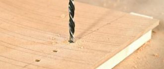
Make a marking (0.8 cm from the edge and 5–11 cm along the product), then make a notch at the marked point using an awl; this is necessary so that the cutting tools do not “walk” in the first seconds of drilling.
Before drilling, you need to make a backing for the part from scraps of unnecessary chipboard. This will make it possible to prevent chips from occurring at the exit of the hole being made.
During the drilling process, make sure that the drill is exactly vertical to the plane of the product.
When the product is drilled through, replace the underlying piece of particle board and substitute something higher in its place so that the workpiece is suspended, and continue working.
At the end
As in all the cases described above, the main principle here is that the drill must be positioned strictly at a right angle to the workpiece. Everything is much more complicated if you need to drill the end of the workpiece. The work must be done very carefully, otherwise the drill may “slip” to the side and thereby damage the product.
When working with the end of an element made of chipboard, you need to remove the cutting tool so that it does not become clogged with chips.
In two at the same time
This method is especially accurate, and it is also the fastest. However, in order to drill a hole in several elements at the same time, they need to be securely fastened before work, for which you can use specialized clamps, clamps and other devices.
End drilling device
It would seem a simple task - to drill parts from the end to install confirmations or dowels. But the problem is that they need to be drilled exactly at an angle of 90. Of course, experienced furniture makers always drill by hand, and they do it quickly and accurately! But at the same time, I think no one can escape the thought of somehow simplifying and systematizing this process, especially when there are a lot of details. It often happens that you have to entrust the drilling process to someone inexperienced, and then many “jambs” arise with the joining of parts. And then you think... if only there was some simple machine to show an assistant without skills what he needs to do, and he would drill slowly and efficiently. For face drilling, there are various industrial-made devices, both stationary for a workshop or garage, and mobile. They are called drilling and additive machines. But all novice furniture makers and “do-it-yourselfers” are interested in household options with a cost tending to zero. How to make such an assistant yourself? While studying the relevant topic on the furniture makers forum, we saw that there are probably as many devices for drilling as there are furniture makers, everyone considers their device the most convenient. In principle, this is correct to some extent, because everyone makes adaptations to suit their tasks and as it is more convenient for them. Let's consider the experience of forum members, perhaps some of you will like a certain idea and make your work easier. First we will look at a device proposed by the user Babel.
The principle of the device itself is not new - a chuck with a drill is fixed in the stand and the part is fed onto the drill. It was assembled from what was at hand: a piece of a 60x60cm tabletop, several chipboard scraps, a tape measure, self-tapping screws and thumbscrews. The most expensive part in the device is a small 400W drill. Cheap and cheerful, but it fulfills its main task - it simplifies your work and saves you time. For beginner furniture makers - just a godsend.
To make the device, you will need a powerful milling machine to make grooves for the guide and ruler. The ruler was made from a tape measure cut in half (saving money never hurt anyone). The larger the ruler, the more universal the design will be. For quick setup, it is advisable to have a tabletop of about 80cm.
The drill is fixed between two pieces of this tabletop. On the right, we fasten the scraps with screws, and then drill a 60mm hole perpendicularly with a crown. The height of the drill is adjusted by placing pieces of sandpaper underneath, so that the axis of the drill is at a distance of 8mm from the tabletop.
**************************************** ************************ Another version of the device seems to be more universal, it allows you to drill parts of any length, even 2750 mm, the principle of operation is simple - place the part, press pedal and drill. This is already a semi-automatic system.
Idling.
Drilling in laminated chipboard.
Corrugation for removal of sawdust from the drilling area.
A simple pedal assembly.
The principle of operation and assembly is visible in the photographs and in the video, it looks somewhat more serious than the first option and, in our opinion, it is more convenient, there is even a chip outlet. This is also an excellent option for novice furniture makers on a limited budget, although it’s worth considering a more secure attachment for the drill. The device fully provides accurate drilling at an angle of 90° to the required depth - this is its main purpose. You can install a contact in the pedal, for example from a Zhiguli pedal, to automatically turn on when you press and turn off the drill when you release the pedal - this will save energy and, most importantly, the life of the tool. **************************************** ************************* The third option looks completely industrial, a table with a ruler made on the principle of a format-cutting machine. In this version, unlike the previous ones, the drill is fed onto the part. The engine sits on a carriage taken from a household woodworking machine. It’s like all in one - we put the engine on the carriage, pull the lever and all the problems are solved. For convenience, it is better to move it to the front edge of the table. The engine is installed from a washing machine, if there is a lot of work it is better to install something more powerful, the carriage stroke is about 10 centimeters. An idea from a suvic user can be used as a portable “pocket” conductor.
Simple and reliable, even relatively accurate, as a portable “must have” option for a furniture maker. **************************************** ************************ Well, for a snack, another good simple idea for those who do not have space for stationary structures. The device is designed for both end and face drilling. The lift of the drill is up to 65 mm, the stop is set according to the template and is used in one size for both the end and the face. Large parts (cabinets and long elements) will be easier and more convenient to drill using a jig, but for small products, like kitchen elements, for example, this is it. Setup is very simple, installation and dismantling is easy and quick. **************************************** ************************ In addition to the homemade devices described in the review, there are a large number of serial items; now the market is flooded with various options for rulers, one-time conductors, etc. But before you buy such things, think about their functionality and ease of use, since many of them are not designed to do a lot of work. These are rather devices for “housewives” who are afraid of the drill. And what we see in the review are simple and effective devices made by experienced craftsmen. Whether or not to use the described designs for your own purposes is still up to you, but what is more convenient and reliable will be shown by your experience and the experience of forum members. We hope you will share your experience in the comments to this material. And don’t forget to visit the furniture makers forum. There are tons of useful ideas and topics there.
Recommendations
There are a number of important rules and recommendations that need to be taken into account.
- To prevent the drill from moving sideways from the very first minutes of the drilling process, it is necessary to make a notch in the middle of the planned hole. This is done with an awl, although other sharpened objects will also work: a self-tapping screw, a nail, and the like.
- Reduce speed. Drilling wood should be carried out at low speeds with an electric drill.
- You can reduce or minimize the formation of chips on the bottom surface of the product when drilling through it by performing the work using one of the following methods:
- we create a through-type hole with a small diameter, then drill through it to the center on both sides with a cutting tool of the required diameter;
- To the side where the drill should come out, use clamps to firmly press a flat backing made of wood or fiberboard, drill a hole, and remove the backing.
4. The verticality of the drill is ensured by using a guide for an electric drill; for workpieces that have a cylindrical shape, you can use a special jig, which ensures both centering of the drill and vertical drilling.
If the drilled hole is too large in diameter, you have the opportunity to restore it in the following way: drill the hole to a larger diameter, then insert a wooden dowel (wooden dowel) of a suitable diameter into it and place it on the adhesive. Allow the adhesive to harden and align the top edge of the chopstick flush with the plane using a chisel, then drill the hole again in the same place.
How to make a hole for confirmation, see below.