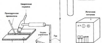
Basic welding diagram
Friction welding is a type of pressure welding. The welded joint is formed in the solid phase, without melting the metal of the welded parts; When the surfaces of the parts to be welded are brought together to very small distances (comparable to between atomic ones), metallic bonds are formed between them, which are similar in nature and magnitude to the interaction forces between atoms in a solid piece of metal. In this case, obtaining a strong welded joint is possible under the condition of vigorous plastic deformation of those volumes of metal of the parts being connected that are located near the interacting surfaces. However, the plasticity of the vast majority of metals and alloys at room temperatures does not meet this condition. To weld them in the solid phase, an artificial increase in the plasticity of the material is required, for example, by heating the parts being joined to sufficiently high temperatures (which, however, lie below the melting point).
Friction welding differs from other types of pressure welding in the method of heating parts or, more precisely, in the method of introducing heat into the parts being welded. In this process, the heating of parts necessary for welding is carried out by directly converting mechanical energy into heat due to the work of friction forces.
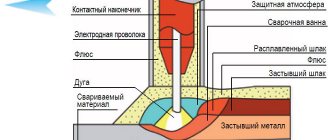
The simplest and most common diagram of such a process is shown in Fig. 36. The two parts to be welded are installed coaxially in the clamps of the machine; one of them is stationary, and the other is driven into rotation around their common axis. Friction forces arise on the mating end surfaces of the parts, pressed against one another by an axial force P. The work expended during the relative rotation of the workpieces being welded to overcome these friction forces is converted into heat, which is released on the friction surfaces and heats the adjacent thin layers of metal to the temperatures required to form a welded joint (when welding, for example, ferrous metals, the temperature at the joint reach 1000-1300° C). Thus, at the joint, i.e. exactly where it is required for welding purposes, an internal source of thermal energy operates, causing rapid local heating of small volumes of metal.
During friction, the ductile metal of the joint is extruded in radial directions under the influence of axial force and tangential forces that arise in the joint when one part rotates relative to another. The extruded metal - burr - has the shape of a double regular ring, characteristic of friction welding, located on both sides of the joint plane.
When ductile metal is squeezed out of the joint in radial directions, the brittle oxide films that covered the end surfaces of the parts being joined before welding begin are destroyed, and their fragments, as well as combustion products of adsorbed fatty films and other foreign inclusions, along with the metal, are removed from the joint into a flash.
Heating is stopped by a quick (almost instantaneous) cessation of relative rotation. In this case, the cleaned end surfaces of the parts being connected are brought into contact, the metal of which has been brought to a state of increased ductility. To obtain a strong connection, it is enough to subject the metal prepared for welding to strong compression—forging it. This is achieved with the help of an axial force that continues to act for some time.
Thus, the strength of the resulting welded joint is directly related to:
firstly, with the amount of plastic deformation of the ends of the parts being welded, a measure of which can be the convergence of the parts when the metal is displaced into the burr - “sediment”;
secondly, with the forging mode.
In turn, the degree of plastic deformation depends on the energy introduced into the parts being welded, the magnitude of the axial force and some other factors.
The main parameters of the friction welding process are the frequency of relative rotation of the parts being welded; the magnitude of the axial force during heating; the amount of precipitation during heating; the magnitude of the axial forging force; duration of application of forging force.
The first two parameters determine the heating power, and in combination with the third, the amount of energy introduced during heating; the last two parameters are responsible (together with the first three) for the quality of the welded joint.
The amount of precipitation during heating is often replaced by the duration of heating, since these values are almost directly proportional.
Heating and forging forces are usually specified in the form of specific pressures, since it has been established that their optimal values are directly proportional to the cross-sectional area of the parts being welded at the welding site; the magnitude of the total axial force is determined as the product of this area and the specific pressure.
The numerical values of the main process parameters depend on the properties of the materials of the parts being welded and on the dimensions of their sections; they are determined experimentally and summarized in technological tables of friction welding modes, which are given in the relevant sections of the reference book.
Approximate modes usually used for friction welding of workpieces made of low-carbon and medium-carbon steel are given in Table. 10.
Advantages of STP
The study of FSW made it possible to select welding modes when joining different groups of alloys. Despite the fact that FSW was initially developed to work with metals with low melting points, such as aluminum (660 °C), it was later used to join nickel (1455 °C), titanium (1670 °C), iron (1538 °C ).
Research shows that the weld obtained in this way is completely consistent in its structure with the metal of the parts being welded and has higher strength indicators, lower labor intensity and low residual deformation.
A correctly selected welding mode guarantees compliance of the weld material and the metal being welded according to the following indicators:
- fatigue strength:
- bending and tensile strength;
- impact strength.
Advantages
Strictly localized heat generation in the near-surface layers of parts during friction welding is the main feature of this process, which determines its energy and technological advantages, which primarily include the following.
High performance
. The volume of the thin layer of heated metal is so insignificant that the entire heating cycle usually fits into a very short period of time - from a few seconds to 0.5 minutes (depending on the properties of the material and the cross-sectional dimensions of the parts being welded); this determines the high productivity of the friction welding process; Only electric contact butt welding can compete with it in this regard.
High energy performance of the process
. Local heat generation and small volumes of metal heated during friction welding determine a very high efficiency of the friction welding process; energy and power consumption during friction welding is 5-10 times less than, for example, during electric resistance butt welding (Fig. 37).
High quality welded joint
. With the correctly selected welding mode, the metal of the joint and adjacent areas has strength and ductility no less than the base metal of the parts being joined; the joint is free from pores, cavities, various types of foreign inclusions and other macro-defects, and the metal of the joint and thermally affected zones as a result of shock thermomechanical effects (rapid heating and cooling in the presence of high - several hundred atmospheres - pressures), in nature close to the regimes thermomechanical processing of metals, acquires an equiaxial and highly refined structure (Fig. 38).
Stable quality of welded joints
. Parts friction welded under the same conditions are characterized by repeatable mechanical properties; the variation in tensile strength, bending angle, impact strength and other indicators in a batch of parts welded at a constant mode does not exceed 7-10%.
This makes it possible to reasonably apply selective quality control of a batch of parts, which is especially important in the current absence of simple, reliable and cheap methods of non-destructive testing of butt joints suitable for use in welding shops.
Independence of the quality of welded joints from the cleanliness of their surface
. When friction welding there is no need to clean the surfaces brought into contact before starting the process; Unlike, for example, resistance welding, the side surfaces of parts can also remain uncleaned, which significantly saves the time of auxiliary operations.
Possibility of welding metals and alloys in various combinations
. The friction welding process allows you to make strong connections not only of the same, but also of different metals and alloys, even those that are either not obtained by other welding methods at all, or their production is associated with great difficulties. For example, combinations of dissimilar materials such as aluminum with steel, copper with steel, titanium with aluminum, copper with aluminum and others have been studied and mastered in industrial production.
Hygienic process
. Friction welding is distinguished from other types of welding by the hygiene of the process: the absence of ultraviolet radiation, harmful gas emissions and hot metal splashes.
Ease of mechanization and automation
. Friction welding is performed on special machines; the main parameters of the process are relatively easy to program, and, as a rule, all equipment is either semi-automatic with minimal use of manual labor, or automatic, the operation of which occurs without human intervention.
Modern methods of automatic welding of large thin-walled products made of aluminum alloys
© 2016 A.M. Tupitsyn* **, E.A. Gladkov**, A.V. Chernov***
*
SVARBI LLC , Moscow , Russia
** Moscow State Technical University named after .
N. _ E. _ Bauman , Moscow , Russia
*** Volgodonsk Engineering and Technical Institute
- branch of the National Research Nuclear University " MEPhI ", Volgodonsk , Rostov region , Russia
The article analyzes the technological capabilities of modern methods of automatic welding of large-sized thin-walled products for critical purposes from aluminum alloys.
The types, advantages and disadvantages, types of defects that appear when using arc, friction, laser and hybrid methods are considered.
Based on the analysis results, the most optimal and rational welding method was selected.
Keywords
: automatic welding, aluminum welding, welding of large-sized thin-walled products, arc welding, friction welding, laser welding, hybrid welding.
Received by the editor 02/02/2016
INTRODUCTION
Aluminum alloys are difficult to weld materials. High thermal conductivity, heat capacity and cooling rate, a tendency to form pores and hot cracks [1], and the presence of an oxide film complicate the process of obtaining high-quality compounds.
However, aluminum alloys are used in many industries: aviation, aerospace, transport, etc., since they have a very low density, are practically comparable in specific strength to other structural steels and alloys, and have high corrosion resistance and heat resistance [2].
When manufacturing critical structures from aluminum alloys (especially large-sized ones), it is important to pay attention to choosing the optimal welding method that can compensate for the negative properties of aluminum alloys, as well as ensure a strong, defect-free connection while maintaining the geometry of the structure.
In addition, it is necessary to evaluate the possibility and simplicity of mechanization and automation of the process, since ensuring high productivity in most cases is an important criterion when choosing a method, and reducing the influence of the human factor in the welding process will reduce the likelihood of defects.
A study of literary sources has shown that there are many methods of welding aluminum alloys: arc, friction (friction), laser, hybrid, which can be used in welding various structures made of aluminum alloys (Fig. 1).
Rice. 1.
– Aluminum welding methods
1. FRICTIONAL METHODS
Friction welding is welding due to the release of heat during friction between the working tool and the workpiece.
1.1 Types
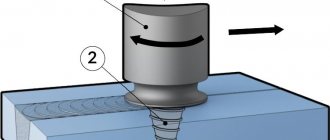
A variation of friction methods is friction stir welding (Friction Stir Welding). Welding occurs by heating a rapidly rotating spindle with a pin in the center, which is immersed in the joint of two parts and moves along the joint line.
In addition to the standard FSW, there are modernized methods [3,4] that make it possible to compensate for some disadvantages:
FSW with two spindles
(Self-reacting or SR-FSW).
This is a method in which, instead of a rigidly fixed lining, another spindle is used, located on the opposite side of the working spindle. The method allows you to obtain a more symmetrical seam [4], and there is no axial force that occurs in conventional FSW, which allows you to reduce the size and complexity of fixtures .
FSW with heating
(Assisted FCW).
In this method, the product is heated using TIG welding, laser welding or an induction heating system [3]. The stress in the spindle is reduced, which leads to reduced tool wear.
FSW with pulsed spindle rotation
(Pulsed FCW).
This method uses pulsed changing speed of rotation and/or movement. The spindle rotates in full reverse mode. The experiments made it possible to obtain a symmetrical microstructure in the weld zone. At the same time, the seams had a higher tensile strength and relative elongation [3].
1.2 Advantages and disadvantages
FSW is easy to automate, heat input is minimal, since there is no melting of the weld pool, no burnout of alloying elements, no additional heat treatment of the seam is required, the method allows for high welding productivity, which is especially important when welding large-sized structures.
The process does not require the use of wires, rods, fluxes, or protective gases, which significantly reduces the cost of the structure.
When using FSW, there is a need for two-sided rigid fixation of products, which makes it impossible to use the method for welding complex spatial structures. The disadvantage of this method is also the high cost of the equipment.
FSW is a relatively new method, so another problem is the lack of “knowledge” of the process; it is difficult to find welding technology and modes in open sources.
1.3 Defectiveness
The absence of a weld pool solves the main problems when welding aluminum: the formation of porosity, crystallization cracks, and burnout of alloying elements [5].
The main defect in friction stir welding is lack of fusion at the root of the weld. When performing FSW, a hole remains at the end of the seam where the working tool exits the joint. Characteristic defects are concavity, the possibility of the appearance of solid inclusions: fragments of working tools, residues of dirt, oil, grease [6].
1.4 Sensitivity to assembly and welding anomalies
With the help of FSW it is possible to weld in any spatial position. To ensure a high-quality welded connection, it is necessary to ensure high precision in the assembly of the structure.
2. LASER METHODS
Laser welding is the welding of joints using a highly concentrated heat source.
2.1 Types
Laser welding of aluminum alloys is performed either by traditional CO2 lasers or by more modern and advanced fiber lasers.
Lasers can be either periodic (pulsed) or continuous [7].
It is recommended to use fiber lasers as a radiation source, since the power level required to start melting is 2 times less than that of a CO2 laser [8], and the efficiency is 1.5-2 times higher than the efficiency of a CO2 laser (30% versus 15-20%) [9]. At the same time, compounds obtained by CO2 and fiber laser radiation practically do not differ in appearance and macrostructure [8].
2.2 Advantages and disadvantages
The advantages of laser welding are minimal heat input, high concentration of heat: the volume of the weld pool is several times smaller than with arc welding [8,9], minimal deformation: 3-5 times lower than with arc welding [7], high productivity for welding speed: 50-200 m/h or more [7,9], low degree of warping and deformation of parts [8].
The disadvantages of this method are the high cost of equipment, a decrease in the strength characteristics of the joint due to sagging of the weld pool [9], and for welding in an automated mode, the entire production cycle must be carefully structured.
2.3 Defectiveness
During laser welding, due to the rapid cooling of the melt, aluminum alloys are prone to the formation of cracks, the appearance of scaly welds is observed [8], and when using a CO2 laser, a large number of pores appear [10].
2.4 Sensitivity to assembly and welding anomalies
This method makes it possible to carry out work in various spatial positions.
Laser methods are sensitive to the size of the gap between the edges, which significantly increases the complexity of assembling structures, since there is a need to ensure high assembly accuracy (Table 1) [7,11].
Table
1.
– Dependence of the gap size on welding speed and metal thickness
| Metal thickness, mm | Welding speed, mm/sec | Maximum permissible |
| gap size (b), mm | ||
| 0,8 – 1,5 | 5,5-22,2 | 0,12 |
| 22,2-33,3 | 0,10 | |
| 1,5 – 3,0 | 5,5-22,2 | 0,15 |
| 22,2-33,3 | 0,12 |
3. ARC METHODS
Arc welding is a welding of joints that uses an electric arc to heat and melt metal.
3.1 Types
Arc welding methods for aluminum are divided into two large groups: using a non-consumable tungsten electrode (TIG) and using a consumable wire electrode (MIG).
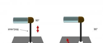
TIG.
The most popular TIG welding technologies are methods using dynamic arcs, for example, coldArc from EWM [12], which allows you to adjust welding parameters so that when the distance between the electrode and the product changes, the supplied energy maintains a constant component [12].
To increase the molten metal and welding speed, additional filler wire is used: cold or hot (Fig. 2).
MIG.
MIG welding methods for aluminum alloys are mainly divided into pulsed and cold processes.
“Cold” methods make it possible to reduce the amount of heat introduced into the base metal due to a sharp decrease in the welding current during a short circuit. Drop separation occurs due to gravitational forces. In the Fronius CMT process, drop separation also occurs using the reverse movement of the welding wire [13]. Similar technologies have been developed by other manufacturers: ColdArc (EWM,) ColdMIG (Merkle), WiseThin (Kemppi), PrecisionPulse (Lincoln Electric).
Rice. 2.
– Scheme of TIG welding with additive
Pulse methods allow you to increase the welding speed due to a pulsed increase in current.
Welding of aluminum products using pulse technology can be done using Syncro Pulse, PMC (Fronius), Pulse-On-Pulse (Lincoln) processes
Electric), SpeedPulse (Lorch), etc.
Pulse-On-Pulse and SpeedPulse processes use high- and low-power pulses. This solution made it possible to facilitate the process of making welding joints, improve the appearance of the seams, increase the penetration depth and welding speed [14].
The PMC (Pulse MultiControl) process, due to the high-frequency component, allows you to evaluate the position of the drop and then change the welding parameters, achieving a smooth flow of the drop into the bath. The process automatically maintains a minimum arc, resulting in reduced spatter (Fig. 3).
Rice. 3
. – The process of a drop “flowing” into the weld pool
To increase the welding speed, tandems are used (welding is carried out with two or more wires at once). For example, two wires are used in the process
Tandem MIG from Lincoln Electric.
3.2 Advantages and disadvantages
The main advantage of arc methods is the cost-effectiveness of the process compared to other listed methods, ease of automation, and the absence of specialized equipment.
The disadvantages of this method are lower welding productivity,
the need to use a large amount of materials, relatively low energy concentration in the arc, instability of arc combustion at high speeds [11].
3.3 Defectiveness
The large amount of heat introduced during welding can cause the product to deform. The use of rational design and pulsed or cold processes will reduce heat input and, therefore, deformation of the structure.
When welding aluminum alloys, there is a possibility of pores and undercuts. Careful preparation of the surface before welding and adherence to the technology will avoid the formation of pores, and the correct selection of the welding mode will prevent the formation of undercuts.
3.4 Sensitivity to assembly and welding anomalies
This method allows you to make high-quality welded joints in all spatial positions.
Among the methods listed in the article, arc welding is the least sensitive to product and assembly anomalies: uneven joint width, the ability to weld large air gaps.
3.5 Hybrid methods
These methods combine two or more processes, which allows you to use the advantages of each and neutralize their disadvantages.
Hybrid laser - arc .
Aluminum welding is carried out by a laser in combination with a non-consumable or consumable electrode [11].
The method is used when it is necessary to weld sheets automatically at high speed, low heat input and high quality welded joints.
The advantages are reduced requirements for the accuracy of assembly of parts [11], high stability at high welding speeds (over 60 m/h [15]), reduced beam power, reduced energy consumption, increased equipment efficiency (1.5-2 times compared to laser [11]), reduction in costs for consumables (2 times [16]).
The disadvantages are the tendency to form undercuts, erosion of the non-consumable electrode [10], and the high cost of the equipment.
Hybrid laser - plasma welding .
An important advantage of plasma welding is cathodic cleaning of the surface of the product [11,17].
The microplasma component can significantly reduce the cost of equipment and increase the stability of arc combustion [11].
The disadvantage of the method is sagging of the seams, the formation of undercuts and internal pores [15], and the inability to achieve a stable process at high welding speeds [11].
By combining microplasma and laser welding, it is possible to obtain a high-performance process with increased quality of welded joints [18], stabilize the process at high speeds, and reduce the dependence of the process on the optical properties of the surface. When welding, the surface is cleaned from the oxide film[11].
Double beam laser welding.
This is a method in which a weld pool is formed by exposure to two laser beams.
Currently, this technology has not been sufficiently studied, therefore it is practically not used in industry [19].
The advantages of this method are the elimination of burns, reduction of pore formation [11], the possibility of welding parts of different thicknesses and removing the oxide film with one of the lasers.
CONCLUSION
The article examined various methods of welding large-sized thin-walled structures for critical purposes made of aluminum alloys.
Despite the high productivity and the possibility of welding with low heat input, laser methods are problematic to use in welding, since it is necessary to ensure high assembly accuracy and maximum (“pharmacy”) cleanliness of production. Due to the high cost of equipment, the use of these methods is only advisable for mass production of structures.
Friction stir welding is also difficult to use in these structures, since the method is relevant only for joining simple-shaped products, when welding which it is possible to ensure rigid two-sided fastening.
The use of hybrid welding methods is relevant, but due to the small amount of information in open sources, the problem of selecting a welding mode and evaluating these processes according to the “price-quality” criterion arises. The high cost of equipment also narrows the scope of application of these methods.
The MIG arc welding method, through the use of pulsed or “cold” processes, will solve the problem of high heat input when welding aluminum alloys. The reduced sensitivity of the method to anomalies in the assembly of a butt joint, compared to laser welding, significantly reduces the labor intensity of manufacturing a complex spatial structure, and the use of adaptive process control algorithms will expand the technological capabilities of the process and move from manual and mechanized welding to automated welding while maintaining a high indicator according to the criterion “ price quality".
In addition, through automation and mechanization of the process, it is possible to significantly increase welding productivity and increase process stability. The relatively low cost of equipment and ease of implementation of the welding process based on high-speed inverter power supplies are also a serious advantage when choosing this method [20].
Based on the identification of the welding process as a control object, the authors have planned work on the development and implementation of an automated complex for automatic welding of the critical products made of aluminum alloys mentioned in the article with the solution of problems of geometric and technological adaptation of the welding process to technological disturbances of various physical natures.
Having analyzed the technological capabilities of the modern welding methods discussed above, the authors came to the conclusion that for the tasks at hand, the most rational and optimal methods are MIG/TIG welding methods using pulsed technologies. In their further research, the authors will pay attention to improving these methods based on the development and implementation of automated equipment using digital control and process control, as well as the use of automated heads with high-speed power supplies and adaptive robots.
BIBLIOGRAPHY
1. Mathers G. The Welding of Aluminum and its Alloys. Cambridge: Pub. Woodhead Publishing, Ltd, 2002, 242 p.
2. Makarov ,
E. _ L. _ and etc .
Theory of weldability of steels and alloys [Text] / E.L. Makarov, B.F. Yakushin. – M.: MSTU im. N.E. Bauman, 2014. – 487 p.
3. Dawes CJ Friction stir welding. TALAT. 1999, p. 13. Available at: https://mitpublications.org/yellow_images/1361513532_logo_File%204.pdf
4. Thomas WM, Norris IM, Staines DG, Watts ER Friction stir welding – process developments and variant techniques. SME Summit. Oconomowoc, 3-4 August 2005, Milwaukee, USA. pp. 1–21. Available at: https://hegesztesportal.hu/tudastar/wt_fsw.pdf
5. Threadgill PL, Leonard AJ, Shercliff HR, Withers PJ Friction stir welding of aluminum alloys. International Materials Reviews. 2009, Vol. 54, Issue 2, ISSN 0950-6608, DOI: 10.1179/174328009X411136, pp. 49–93.
6. Gibson BT, Lammleinb DH, Praterc TJ, Longhurstd WR, Coxa CD, Balluna MC, Dharmaraja KJ, Cooka GE, Straussa AM Friction stir welding: Process, automation, and control. Journal of Manufacturing Processes. 2014, Vol. 16, Issue 1, ISSN 1526-6125, DOI: 10.1016/j.jmapro.2013.04.002, pp. 56–73.
7. Ignatov ,
A. _
Laser welding of steels with powerful CO2 lasers. Part 1 [Text] / A. Ignatov // Photonics. – 2008. – No. 6. – P. 8.
8. Shiganov ,
I. _ N. _ and etc .
Laser welding of aluminum alloys [Text] / I.N. Shiganov, A.A.
Kholopov // Photonics. – 2010. – No. 3. – P. 6–10.
9. Shiganov ,
I. _ N. _ and etc .
Laser welding of aluminum alloys for aviation purposes [Text] / I.N. Shiganov, S.V. Shakhov, A.A. Kholopov // Engineering journal: science and innovation. – 2012. – No. 6(6). – P. 34–50.
10. Bagger C., Olsen FO Review of laser hybrid welding. Journal of Laser Applications. 2005, Vol. 17, No. 1, DOI 10.2351/1.1848532, p. 13.
11. Grigoryants ,
A. _ G . and etc .
Hybrid laser welding technologies [Text] / A.G. Grigoryants, I.N. Shiganov, A.M. Chirkov. – M.: Publishing house of MSTU im. N.E. Bauman, 2004. – 49 p.
12. Innovative TIG/plasma welding processes from EWM [Text]. – [B.M.], 2014. – P. 24.
13. Gladkov ,
E. _ A . and etc .
Automation of welding processes [Text] / E.A. Gladkov, V.N. Brodyagin, R.A. Perkovsky. – M.: MSTU im.N.E. Bauman, 2014. – 421 p.
14. Lincoln Electric. Pulse-On-Pulse GMAW (MIG). 2006, p. 4.
15. Shelyagin ,
V. _ A . and etc .
Technological features of laser, microplasma and hybrid laser-microplasma welding of aluminum alloys [Text] / V.A. Shelyagin, A.M. Orisic et al. // Automatic welding. – 2014. – T. No. 5 (734). – P. 35–42.
16. Paul ,
K. _ and etc .
Hybrid laser welding [Text] / K. Paul, F. Riedel // Photonics. – 2009. – No. 1. – P. 2–5.
17. Paton ,
B. _ E. _ and etc .
Microplasma welding [Text] / B.E. Paton and others - Kyiv: Naukova Dumka, 1979. - 248 p.
18. Paton ,
B. _ E. _ and etc .
Hybrid laser-microplasma welding of small thickness metals [Text] / B.E. Paton et al. // Automatic welding. – 2002. – No. 3. – P. 5–9.
19. Grezev ,
N. _ IN .
Development of a method for double-beam laser welding of structural low-alloy pipe steels: abstract thesis. Ph.D. tech. Sciences [Text] / N.V. Gryazev. –
M., 2010. – 18 p.
20. Gladkov ,
E. _ A .
Management of processes and equipment during welding [Text] E.A. Gladkov – M: , 2006. – 432 p.
ELECTRONIC RESOURCES
Scientific and practical journal “Global Nuclear Security” https://gns.mephi.ru/ru.
Return to list
Flaws
Friction welding is not a universal process
. With its help, only such pairs of parts can be connected, at least one of which is a body of revolution (round rod or pipe), the axis of which coincides with the axis of rotation; in this case, the other part can be of any shape, but must have a flat surface to which the first part is welded. In Fig. Figure 39 shows the main connection options.
This drawback, however, does not significantly limit the applicability of friction welding; An analysis of the nature of production shows that in the mechanical engineering industries the number of parts with a round cross-section is up to 50-70% of the total number of welded parts.
Some cumbersome equipment
, as a result of which the process cannot be mobile; the process is feasible only if the workpieces to be welded are supplied to the machine (welding of small parts to massive structures using portable machines is excluded).
Curvature of rolled texture fibers in the plastic deformation zone
— fibers near the joint are located in radial directions and extend to the outer (side) surface of the welded part. In parts operating under dynamic loads, a joint with such an arrangement of fibers can be a source of fatigue failure, and in other parts operating in aggressive environments, it can be a source of corrosion. The best way to prevent these defects is to preserve the burr on the part. Other means of combating these undesirable phenomena can significantly increase the cost of manufacturing the part.
You should also point out the inconveniences associated with the need to remove the flash when this turns out to be necessary for design reasons. This requires additional time either on the welding machine or at a separate workstation.
Features of joint formation during friction welding. Despite its apparent simplicity, the process of friction welding of metals is actually very complex and diverse; it is subject to many laws, since phenomena such as heat generation and wear of surfaces during friction coexist and interact in it; continuous formation and immediate destruction of metal bonds between mating surfaces in the process of their relative movement; almost instantaneous heating and very rapid cooling of small volumes of metal in the presence of very high (reaching thousands of atmospheres) specific pressures; elastoplastic deformations in microvolumes of protrusions of rough surfaces and in macrovolumes of metal layers adjacent to these surfaces; hardening and recrystallization of metal; mutual diffusion, as well as the introduction of macroscopic particles of metal from one of the parts being welded into the body of another, etc.
The theory of friction welding is complex and far from being developed. However, the studies that have already been carried out make it possible to present a qualitative picture of the phenomena occurring in the joint during welding.
In Fig. Figure 40 shows a characteristic (experimental) curve of changes in the moment of friction forces M over time (since the rotation frequency n is constant throughout the process, this curve on a different scale characterizes changes in power consumption, and the area limited by it, the corresponding ordinates and the abscissa axis, the expended energy). The process begins with static friction M0, then (in phase τ1) boundary friction takes place, as a result of which the temperature of the friction surfaces at individual points increases, these points are cleared of oxide and fatty films, the metal is plasticized, and metal bonds are formed between the friction surfaces - bridges " grasping." During the ongoing relative motion of the friction surfaces, these bonds are destroyed, which consumes additional energy. The increase in the torque (and power) of friction in phase τ2 initially characterizes the rapidly growing process of increasing the number of adhesion bridges on the friction surfaces; at the same time, the average temperature also increases; the rate of this process decays over time (curve 1 in Fig. 41). With increasing temperature, another process occurs, characterized by curve 2 in Fig. 41, is the process of reducing the strength of the metal and the resistance of bridges to destruction. The product of these two functions (they are considered close to exponentials) determines the presence of a maximum (curve 3 in Fig. 41); This also determines the maximum on the torque curve, after which the torque values begin to decline (phase τ3) to a certain steady-state value. At the beginning of this phase, intense macrodeformation of the surfaces of the parts being welded appears with the displacement of metal from the joint into the flash and, accordingly, the parts are brought closer together in the axial direction (the so-called heating upset). When the moment of force reaches a steady-state value, the settling rate also stabilizes, and a “quasi-stationary” state occurs, the beginning of which is the basis for stopping the heating stage.
At this point, the metal of the joint is completely prepared to form a welded joint, but as long as the rotation of one part relative to the other continues, the joint cannot occur. As soon as the movement stops (the previously formed metal bonds are no longer destroyed), the formation of a welded joint begins. By analogy with forge (forge) welding, the heated and ready-to-weld metal must be “forged”, i.e., compressed with an axial force. This fourth phase (second stage) of the process begins immediately after the rotation stops and usually lasts for several seconds until the joint metal cools to the lower limit of forging temperatures.
The axial force of forging can be equal to the force during heating, but it can also be (in many cases, especially when materials of low ductility are subjected to welding) increased.
Most often, the forging force is chosen to be twice as large as the heating force.
Joint plastic deformation of the metal of the parts being welded and its flow in the plane of the joint both in the heating stage and in the forging stage is one of the main conditions for the formation of a strong joint.
Plastic deformation of metal in microvolumes is important for the process; due to this phenomenon, the specific pressures are redistributed over the cross section during the heating stage: a heated metal is less resistant to deformation than a colder one, therefore the acting axial force is perceived by the colder sections of the friction surfaces, as a result of which they heat up and deform faster. This also explains the fact that areas of the friction surface located near the axis of rotation, the temperature of which should be minimal, quickly heat up to almost the same temperatures as the peripheral areas of the friction surfaces (Fig. 42).
Disadvantages of the method
Despite its many advantages, the friction welding method has accompanying disadvantages:
- Lack of mobility. FSW involves the connection of fixed parts that are rigidly fixed in space. This imposes certain properties on friction stir welding equipment, such as immobility.
- Low versatility. Bulky equipment is configured to perform the same type of operations. In this regard, welding fixtures are designed for specific tasks. For example, for welding car sides on a conveyor belt, and for nothing else.
- The weld seam has a radial structure. In this regard, with certain types of deformation or when the part is operating in an aggressive environment, weld fatigue may accumulate.
Application area. Section shape and dimensions
Friction welding (the basic and most common process scheme) is used to join parts end-to-end (in this case, either both or one of them must have a circular cross-section at the welding site) and to form T-shaped joints of a round part “butt-to-end” to a flat surface.
In principle, the cross-sectional dimensions of the welded parts are not limited, but there are rational limits; the world practice of using friction welding does not yet know of cases of connecting rods with a diameter of <0.75 mm; There are no known cases of welding of solid-section parts with a diameter >200 mm. In the USSR, friction welding in industrial production is used to connect parts with a cross-section of 50-10,000 mm2. These limits are determined by the rated power (NH) and the maximum axial force (Poc) of the machine used in accordance with the following expressions:
The same expressions can be used when choosing the required equipment based on the given dimensions of the parts and the properties of the material from which they are made (the used values of Nsp and Psp are given in the corresponding section of the reference book).
Materials
. We have accumulated extensive experience in the industrial use of friction welding of various materials of the same name, as well as dissimilar metals and alloys. Ferrous metals are welded well (cast iron is an exception).
Equal-strength joints are obtained by welding low-carbon, medium-carbon, low- and medium-alloy steels of the same name; Heat-resistant steel welds well. Steels of all the classes mentioned above can be welded well in various combinations with each other, as well as high-speed steel grades P9 and P18 with structural steel grades 40 and 40X (and close to them).
There are some technological difficulties in welding such dissimilar materials as high-speed steel of increased heat resistance with structural steel; Some heat-resistant precipitation-hardening alloys with structural steel are difficult to weld and require forced heat release.
Aluminum with all its alloys, copper, brass and other non-ferrous metals of the same name are well welded.
Strong and ductile joints are formed by friction welding aluminum with copper, copper with steel, aluminum with steel. Steel does not weld well with aluminum alloys containing more than 3% alloying components.
Strength properties of connections
. Laboratory studies, confirmed by many years of operational experience, have shown that, with correctly selected friction welding modes, it is possible to obtain joints that are equal in strength to the base metal. Static tensile and bending strength, relative elongation, impact strength, fatigue strength, i.e. almost all the main mechanical indicators of the joint metal, are at the level of the corresponding indicators of the base metal of the parts or close to them.
This made it possible to use friction welding in the industrial production of a wide variety of products, including very important ones.
Branches of production. Friction welding is widely used in leading industries in the manufacture of:
in the automotive industry - steering parts, cardan shafts of cars and trucks, axle shafts, rear axle housings of cars, valves of internal combustion engines, hydraulic system cylinders, etc.;
in the tractor industry - steering parts, planetary gears, power take-off shafts, rollers, tracks, diesel engine turbocharger rotors, etc.;
in the electrical industry - parts of high-voltage equipment, terminals of paper-oil capacitors, acid batteries and ignitron anodes, pistons of pneumatic cylinders of welding machines, etc.;
in tool production - in the mass production of end cutting tools (mills, drills, taps).
In Fig. Figures 43 and 44 show some typical applications of friction welding.
The most effective areas of use: in the manufacture of round parts with a stepped profile along the length by welding them from blanks of different diameters; in the manufacture of composite parts from different materials in order to save the more expensive or scarce one; in the manufacture of welded-stamped, welded-forged and welded-cast parts; when designing parts specifically for friction welding, taking into account its features and capabilities.
Application area
The technology is most widely used in mechanical engineering, primarily in tool production. It is also used in the assembly of internal parts of nuclear reactors. Friction joining of aluminum and magnesium alloy workpieces is popular in electrical engineering, electronics, and aerospace. The technology is also used in transport engineering. The radial method is used in the production of equipment for the mining and processing industries.
Relatively recently, friction welding began to be used in shipbuilding and food engineering.
The technology demonstrates efficiency and a tendency to replace traditional welding methods in areas such as:
- for replacing soldered and riveted joints;
- to replace contact electric welding;
- for restoration of products and complex tools;
- for welding workpieces to prepared surfaces.
Friction welding in decoration
Linear Welding Equipment
Stir Welding Equipment
Separately, it should be noted that the use of technology provides special advantages where high demands are placed on the environmental friendliness of the production process. High energy efficiency, the absence of splashes of molten metal, harmful fumes and combustion products, ultraviolet radiation and minimal fire hazard make the method particularly advantageous.
Equipment
In principle, friction welding can be carried out on any metal-cutting machine that has a chuck on a rotating spindle for securing one of the parts to be welded and a place for installing the second part (lathe, milling, boring, drilling, etc. machines), however, attempts to use metal-cutting machines for welding friction usually leads to their rapid wear; these machines are not designed for modes typical of friction welding; Bearing groups of machines fail, beds break.
Friction welding requires the use of special machines. The basic kinematic diagram of such a machine is shown in Fig. 45. The machine is equipped with a control circuit that connects the operation of all its components into a single cycle.
Most of the currently operating friction welding machines are semi-automatic, which perform this entire cycle automatically, and only placing the workpieces to be welded into the machine clamps and removing the welded part from them is done manually. In large machines designed for welding heavy parts, auxiliary operations are usually mechanized. In recent years, automatic machines with a fully automated (including auxiliary operations) work cycle have begun to appear in a number of countries.
Until the early 70s, almost all friction welding machines were universal and designed for welding a large number of parts of different shapes and sizes. Currently, there is a tendency to create specialized equipment for friction welding; in this case, each machine is designed for welding one or a group of similar parts. Such machines are more highly productive and the vast majority operate in a fully automated cycle. Complex mechanized and automatic lines are beginning to find application, built on the basis of friction welding machines and performing both welding operations and a number of related operations - machining before welding, deburring after welding, and even sometimes quality control of the completed joint. These highly productive units are very promising and will find wide application in the coming years.
Nevertheless, simple, cheap and easy-to-use machines for universal use, although not characterized by high productivity, are still successfully used in repair work, as well as in small production shops with a developed range of processed parts.
Detailed information about friction welding equipment is given in the corresponding section of the reference book. Here, for general guidance, some technical and economic indicators of only one of the semi-automatic machines mass-produced in the USSR are reported (Fig. 46): rated power - 22 kW; maximum axial force 10,000 kgf; range of diameters of welded workpieces 16-36 mm; machine welding time 10-30 s; vehicle weight 2700 kg; overall dimensions in plan 720 X 1800 mm; height 1300 mm.
Advantages and disadvantages
Compared to other types of metal joining, the use of frictional force has good prospects. The method has many advantages:
- the technology is characterized by high productivity, a seam is formed in a few seconds due to the high-speed movement of parts and short-term compression of the workpieces;
- it is possible to obtain strong connections, the percentage of defects is low;
- Consistently good quality of seams: there is no scale, burns, lack of fusion, or porosity;
- no preliminary cleaning of the oxide layer is required;
- the list of welded alloys is wide;
- the technology is safe and does not require conventional welding equipment;
- The process is automated, only large parts have to be installed manually.
Main disadvantages:
- low versatility, the geometry of welded rolled products is limited: rods, pipes, sheet metal, strip, strip;
- dimensional equipment, it is installed permanently, there are no mobile analogues;
- The microstructure of the alloy is disrupted in the area of plastic deformation, the curvature of structural fibers during welding leads to fatigue deformation, and over time the metal loses its former strength.
Types of friction welding
Inertia welding
Inertia welding
was invented in the USA and is widely used there. Inertial welding differs from the conventional friction welding method only in that the energy consumed from the electrical network, converted by an electric motor into mechanical energy, is not supplied directly to the welding site, but is preliminarily (in the intervals between weldings) accumulated in the flywheel of the machine. This feature of the process made it possible to solve some technology issues and equipment design in a unique way.
The process of inertial welding of workpieces to be welded in advance in clamps begins with the fact that the flywheel of the machine is driven into rotation using an electric motor. As the angular velocity of the flywheel increases, the reserve of kinetic energy Ek increases in it, the value of which is determined from the equation
where J is the moment of inertia of the flywheel and the associated rotating parts of the machine; ω is the angular velocity of the flywheel.
When the accumulated energy reaches a given value Зmax, necessary and sufficient for welding parts, and the angular velocity reaches the corresponding value
a special device that responds to the magnitude of the angular velocity will work and send a signal to the mechanism that connects the machine spindle to the rotating flywheel and disconnects the flywheel from the drive motor.
One of the parts being welded is rotated; if the parts were previously pressed against each other by an axial force, then the process of heat generation begins at the joint. The moment of frictional forces MT at the joint is the only (except for friction losses in machine components) braking moment in the system, and, therefore, it determines the braking distance (“coast”)
and duration of braking (welding) tsv; friction work can be written as
The joint solution of the above expressions allows us to determine the welding time as
where k is the proportionality coefficient.
Thus, the welding mode of these parts with the flywheel already selected for them is uniquely determined by only two process parameters - the amount of stored energy and the friction moment at the joint, or otherwise - the initial angular velocity of the flywheel ωmax and the force P (specific pressure) of compression of the parts.
As can be seen from Fig. 47, the heating time during inertial welding is several times less than during conventional friction welding, which is the main feature of this type of welding, which determines its technological advantages; for example, a short-term heating-cooling cycle allows using inertial welding to join such dissimilar materials as titanium with aluminum and other combinations, while with conventional friction welding this is in some cases impossible. It should be noted, however, that in some cases this feature of inertial welding turns out to be harmful: when joining materials that are prone to the formation of hardening structures, for example, high-speed steel with structural steel, due to the transience of the thermal cycle, the joints become brittle, and hardening cracks can form in them.
A significant reduction in the machine time of inertial welding compared to conventional friction welding does not mean, however, that the productivity of the process also increases sharply; with the same power consumed from the network by the machines, and when welding identical workpieces, the time of one welding cycle in both compared types of friction welding is almost the same, since in inertial welding it includes a fairly long acceleration time of a heavy flywheel as a component.
A negative feature of machines for inertial welding is that the process is carried out at high angular speeds with large axial forces, which requires the use of heavy bearing units and clamps that can withstand large radial forces. As a result, machines for inertia welding are more complex, heavier and more expensive than machines for conventional friction welding, and since they do not differ significantly increased productivity, the advisability of their use is limited to those cases when joining materials in combinations that cannot be welded by conventional friction welding (aluminum - titanium and etc.)
Orbital welding
Orbital welding
is a type of friction welding and is distinguished by the fact that it allows joining not only round workpieces, but also workpieces of any arbitrary cross-sectional shape. This is achieved by rotating both workpieces to be welded at the same angular speed in the same direction (synchronously and in phase). In this case, even if the ends of the workpieces were pressed against each other, friction forces between them cannot arise, as long as the axes of rotation of both workpieces coincide. It is enough to shift one of them parallel to itself by a certain amount of eccentricity e, and friction will immediately arise at the joint, heat generation will begin, etc.
This process diagram (Fig. 48) differs from other types of friction welding in that each point at the end of one of the workpieces being welded describes circles relative to the corresponding point at the end of the second workpiece with an angular velocity equal to the angular velocity of the workpieces. Consequently, the heat generation power over the entire friction surface is constant and is determined, as usual, by the value of the specific pressure, which in this case can be found from the expression
and its numerical values should be within the usual limits for friction welding - from 0.5 to 2 m/s (for ferrous metals and aluminum). The heat generation process is completed as a result of the forced alignment of the axes of the still rotating workpieces; at the same time, forging pressure is applied to the workpieces being welded, and their joint rotation stops; By the time it comes to a complete stop, the part is welded.
In addition to the mentioned feature - the ability to weld parts of non-circular cross-section, orbital welding has another important advantage - increased productivity.
When orbital welding, there is no need to align the axis of the parts being welded with the axis of rotation, and, therefore, instead of one pair of workpieces on faceplates mounted on machine spindles, at different distances from the axis of rotation, not one pair of workpieces, but several such pairs can be fixed and welded simultaneously ; in this case, the power of the machine and the magnitude of the axial force must be increased accordingly.
By using orbital welding, due to the synchronous rotation of the workpieces, it is possible to connect workpieces that, after welding, must be strictly oriented according to the angle of rotation.
The orbital welding process has not yet found industrial application, which is likely due to the lack of popularization of orbital welding capabilities.
Orbital welding. Orbital Welding - ESAB
Video: ESAB.ru
In what areas is it used?
Industries such as the automotive industry are constantly working on how to increase the strength properties of a product while reducing its weight. In this regard, there is a continuous introduction of new materials that were previously unknown due to the complexity of processing. Increasingly, power elements such as subframes, and sometimes entire bodies, are made of aluminum or its combination with other materials.
Thus, in 2012, Honda used additive technologies and friction stir welding to produce subframes for its cars. They introduced a combination of steel and aluminum.
When producing welded aluminum body elements, burning of metal sheets may occur. STP does not have this drawback. In addition to the fact that electricity consumption is reduced by 1.5-2 times, the costs of consumables, such as welding wire and shielding gases, are reduced.
In addition to automobile production, STP is used in the following areas:
- Construction production: aluminum support trusses, bridge spans.
- Railway transport: frames, wheeled bogies, wagons.
- Shipbuilding: bulkheads, structural elements.
- Aircraft construction: fuel tanks, fuselage parts.
- Food industry: various containers for liquid products (milk, beer).
- Production of electrical equipment: electric motor housings, parabolic antennas.
In addition to aluminum alloys, friction stir welding is used to produce copper compounds, for example, in the production of copper containers for the disposal of spent radioactive fuel.
Other variations of the friction welding process
Welding two parts using a third body.
Connecting long (or short, but massive) parts using friction welding is complicated by the fact that bringing such parts into rotation and quickly braking is associated with significant difficulties. In this case, a process diagram (variation) of friction welding can be successfully applied, which allows welding of two stationary parts by rotating a third body sandwiched between them. As such a third body, a thin disk with a diameter larger than the diameter of the workpieces being welded can be used (Fig. 49), for ease of gripping the disk with a clamp, or (Fig. 49, a) a relatively long axial insert, the diameter of which can be the same , as well as the diameter of the workpieces to be joined.
Simultaneous welding of three workpieces
- a frequently used technique - in order to increase labor productivity, three workpieces are simultaneously welded, and the middle one (Fig. 49, c) remains motionless during the welding process, and both outer ones are driven into rotation using two separate spindles; the rotation of the outer workpieces can be synchronized and in-phase if mutual orientation of the parts according to the angle of rotation is required, or the rotation of both spindles is carried out without the use of synchronizers.
Vibration welding
. In principle, the process of friction welding of non-circular parts is possible, in which, instead of relative rotation, the reciprocating motion of the end of one of the workpieces being welded relative to the other is used (Fig. 49, d). In practice, this process scheme has not found application, since the welding installation turns out to be very uneconomical: a large proportion of the energy introduced into the machine is wasted uselessly on overcoming inertial forces and on wear and tear of parts and components of the machine itself; If it is necessary to connect non-circular parts by friction, it is more correct to use orbital welding.
What affects the quality of STP
Friction stir welding is a constantly evolving process. But now we can identify several parameters that affect the quality of the connection:
- The force generated by the tool.
- Welding head feed speed.
- Burt size.
- Circumferential speed of rotation of the rod.
- Tilt angle.
- Rod feed force.
Manipulation of welding characteristics allows the joining of dissimilar metals to be achieved. For example, aluminum and lithium. Lithium, due to its low density and high strength, can act as an alloying component of aluminum alloy parts, which makes it possible to use this technology in the aerospace industry.
Friction stir welding can easily replace forging, stamping, and casting when they are used to produce parts from difficult-to-match metals. For example, steels with austenite and pearlite structures, aluminum or bronze steels.
Prospects for the development of friction welding
In a relatively short period of industrial use, friction welding has established itself as a high-performance technological process that makes it possible to obtain high-quality joints of parts from a large number of different metals and alloys of the same and different names and has a number of other important advantages. This is one of the main reasons for the rapid introduction of friction welding in various branches of mechanical engineering. Features of the process allow us to predict the following ways of further development of friction welding:
- development of new varieties of the friction welding process in order to expand the possibilities of its industrial use;
- carrying out technological research in the field of expanding the range of new friction weldable materials and establishing optimal welding modes;
- development of new samples and systems of universal equipment for welding large parts, as well as for microfriction welding;
- creation of simple and cheap universal machines to equip repair shops and production workshops with a large range of processed parts;
- creation of specialized automatic machines and complex lines designed for the production of a large number of similar parts;
- creation of equipment equipped with feedback systems and conducting the welding process in a given mode, without deviations when exposed to disturbing factors, which completely eliminates the possibility of welding defects;
- carrying out research in the field of process optimization and creating (in the future) on this basis self-adjusting automatic machines equipped with computers or connected to them.
Nikolaev G.A. “Welding in mechanical engineering. Directory. T.1"
Read: Rotary Friction Welding
The essence of the process
The joining of metals occurs due to heating in the welding zone using the friction method. The main welding tool for friction stir welding is a metal rod consisting of two halves: a collar and a shoulder.
With its protruding part, the rotating rod is immersed in the material, causing intense heating. Its supply is limited by the shoulder, preventing it from passing through the part being welded. In the heating zone, the material significantly increases its plasticity and, pressed by the shoulder, forms a single mass.
The next step is to move the rod along the welded zone. Moving forward, the collar mixes the heated metal mass, which, after cooling, forms a strong connection.
Types of STP according to the operating principle
Welding processes that rely on friction can be divided into several types:
- Linear friction. The essence of the method comes down to obtaining a permanent connection not as a result of the action of a rotating tip, but due to the movement of parts relative to each other. By acting on the surface at the point of contact, they create friction and, as a result, high temperature. Under pressure, the adjacent parts melt and a welded joint occurs.
- Radial welding. This method is used for the production of large-diameter containers and railway tanks. It comes down to the fact that the joints of the parts are heated by a rotating ring, dressed on the outside. By frictional force it causes a temperature close to the melting point. An example of an enterprise using this technology is the Cheboksary company for the production of Sespel tanks. Friction stir welding occupies the main share of welding work.
- Pin welding. This type replaces the rivet connection. This type is used for overlapping joints. A rotating pin at the point of contact heats up the parts being welded. The high temperature causes melting and the pin penetrates inside. Once cooled, it creates a strong, permanent connection.
Types of STP by level of complexity
Welding operations performed using friction can be divided into planar and volumetric. The main difference between these varieties is that in the first case the welding seam is formed in two-dimensional space, and in the second in three-dimensional space.
Thus, for planar joints, the welding equipment manufacturing company ESAB has developed a 2D LEGIO installation. It is a customizable friction stir welding system for a variety of non-ferrous metals. Different size groups of equipment allow you to weld parts of small and large sizes. According to the marking, LEGIO equipment has several layouts that differ in the number of welding heads and the ability to weld in several axial directions.
For welding work with complex positions in space, there are 3D robots. Such devices are installed on automobile conveyors, where welds of a complex configuration are required. One example of such robots is the Rosio installation from ESAB.