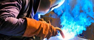
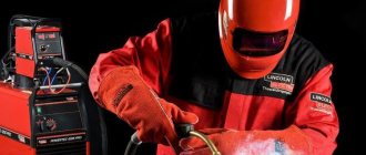
In continuous production, an automatic welding machine completely replaces an experienced welder. With high productivity, without human intervention, it ensures precise connection of parts. Automatic welding is a fully mechanized technology.
The device independently maintains stable arc combustion and supplies filler wire. The process takes place in a closed enclosure. The operator is not exposed to harmful factors. Automatic welders are able to work without breaks and days off. After programming, the welding procedure is fully controlled automatically. With an accelerated process, high-quality seams are obtained.
The essence of automatic welding
The welding automation procedure using electric arc technology is conventionally divided into several operations:
- renewal of the melted rod in a constant mode;
- maintaining the necessary conditions (supplying flux or shielding gas to the working chamber);
- uniform movement of the arc along a given trajectory at a constant speed;
- formation of a suture bead.
In this case, the machine controls:
- the distance between the tip of the electrode and the metal being welded is up to microns;
- welding current strength;
- speed of seam formation;
- depth of heating of the workpiece.
The machines differ in:
- method of protecting the work area;
- movement of the welding arc;
- number of installed electrodes, their type;
- type of operating current.
With such a variety of devices, the essence of the process is the same.
Thanks to automatic installations, manufacturers have been able to increase productivity and quality of welded joints.
Design of a semi-automatic device
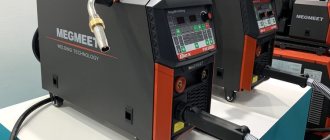
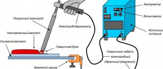
The device is a modular design consisting of a power source, a feed mechanism and a burner. Devices for welding in a shielding gas atmosphere are equipped with cylinders. There are a number of high-performance refrigerated models that connect to a mains or water tank. Semi-automatic devices are lightweight and highly mobile. They can be carried or transported on a chassis to the work site. The devices are used for installation of engineering systems, during repairs in existing production and workshops.
There are also semi-automatic machines of a stationary design - welding stations. They are used in the serial production of metal structures, when most of the seams are short in length (up to 0.8 m).
| The main design difference between a semi-automatic and an automatic is the presence of a burner, which is usually made in the form of a pistol grip. Joining her:
|
Types of automatic welding machines
Based on functionality, any equipment with automatic welding must have the following basic elements:
- an inverter-type current source to ensure stable arcing, maintaining the required current-voltage characteristics;
- heads replacing the electrode;
- a device that ensures the movement of the head or melt bath;
- mechanized additive supply;
- Control block.
All these parts are collected in a single body. It is necessary to provide a table for laying workpieces. The device forms a seam due to the mutual movement of the melt bath and the head. Some of the elements are fixed rigidly, the other is movable. Two types of machines have been developed:
- with a uniform (set) feed rate of the additive into the working area;
- regulation of the rotation of the feed rollers depending on the arc voltage.
Tractor-type automatic machines
They are designed for welding butt and corner joints; they move either along the product being welded (ADF-1002) or along rail guides placed on or near the product being welded (ADG-602, ADF-1202).
The ADF-602 machine is designed for welding in shielding gases, and the ADF-1202 is for submerged arc welding with direct current. Their designs are largely unified. They allow welding both inside and outside the track at a distance of up to 200 mm. The track size is 295 mm. The design allows you to adjust the position of the electrode wire relative to the joint in the transverse direction within 60 mm. When welding under submerged arcs, the position of the electrode is controlled using a light indicator. Regulation of the electrode wire feed speed and welding speed is smooth. The engine speed control system allows you to strictly stabilize the selected speeds.
The ADF-1002 (TS-17) machine is designed for submerged arc welding on alternating current. It has one asynchronous motor connected to both the wire feeder gearbox and the trolley gearbox. This design solution made it possible to create a very compact machine gun. The wire speed and welding speed are controlled by replaceable gears. Due to its small size, it is used for welding internal circumferential seams in vessels with a diameter ≥ 1 m.
Buy
tractor type automatic
Automatic welding technology
The main unit of the device is the current-conducting welding head. Submission in progress:
- additives;
- discharge forming an electric arc.
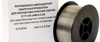
Automatic welding is most often done using filler wire attached to a spool or spool. Due to the roller system, the movement trajectory and speed limit are established. The additive is first straightened and then enters the guide mouthpiece, which is placed above the working area during operation.
Semi-automatic welding technology
The molten metal of the electrode and the parts to be connected needs protection from atmospheric oxygen. There are two technologies to avoid their intense oxidation and burnout of alloying additives.
- Welding in shielding gases. The technology involves the use of solid wire, as well as argon or carbon dioxide. Gases are supplied through the nozzle under slight excess pressure, allowing air to be displaced.
- Flux cored wire welding. Flux-containing filler materials eliminate the need for a protective atmosphere. When melting flux-cored wire, slag and gases are formed, which protect the weld pool from oxidation.
The process of performing semi-automatic welding The
tasks of the operator of a semi-automatic installation include selecting the operating mode of the device (setting the current strength, choosing the polarity) in accordance with the diameter of the electrode and the material, activating the torch and performing the required number of passes along the seam. The wire feed speed (maintaining a constant arc length) is adjusted in automatic mode.
Many modern devices have additional functions that make the welder’s work easier: increasing the voltage when igniting the arc, the ability to switch from direct current to alternating current or pulsed current for joining parts made of non-ferrous metals. Some models can be converted to non-consumable electrode welding or conventional manual welding.
Electronically controlled semi-automatic machines have a built-in memory for saving settings. To switch to another mode, the operator only needs to select the appropriate program number.
Advantages and disadvantages
Visually, seams using automatic technology are much smoother than manual ones. Automatic welding has other advantages:
- Before manual arc welding, welding equipment requires a long time to set up, adjust current and voltage parameters. The use of electronic systems speeds up the setup process.
- The productivity of automatic machines is many times higher than that of a team of welders. No rest breaks are needed, quality does not depend on professionalism.
- The volume of waste is reduced. The number of damaged parts depends on the correct settings of the devices, and not on the human factor.
- Stable weld seam. Automatic welding is valued for its neat, even seam beads of the same height without tears or sagging.
- Cost-effective: limited wire consumption, less energy loss due to spattering and waste.
- Ability to weld metal:
- in places hard to reach for humans;
- confined spaces;
- harmful conditions: increased gas pollution, uncomfortable temperature for humans.
Now about the disadvantages of automatic welding:
- low maneuverability;
- the need for restructuring when changing operations;
- high cost of equipment.
For these reasons, automatic welding devices cannot fully replace welders.
Welding machines are equipped with the following main components; welding head, trolley, control panel, equipment cabinet, cassettes with welding wire.
The main elements of the welding head are the wire feed mechanism, feed rollers, current supply nozzle and devices for the installation movements of the head.
The feed mechanism consists of an electric motor and a gearbox. When using AC electric motors, adjustable gearboxes are used. DC motors can be operated in combination with fixed gearboxes. Feed rollers are located on the output shafts of the gearbox. Their purpose is to provide a stable supply of welding wire without slipping. This is usually achieved by using two pairs of feed rollers. A current-carrying nozzle is attached to the gear housing to ensure electrical contact and guide the wire into the weld pool. The mouthpiece should ensure minimal wandering of the electrode thorn relative to the weld pool. To do this, sometimes a roller straightening mechanism for straightening the wire is installed on the head in front of the mouthpiece. In addition, the mouthpiece must provide reliable electrical contact with the welding wire. The designs of mouthpieces vary depending on the welding method, the diameter and stiffness of the wire. For welding with large-diameter electrode wire (3-5 mm), the most widely used are nozzles with a roller sliding contact. When using wires of smaller diameter (0.b-2.5 mm), tubular mouthpieces are used. Sliding contact is maintained by replaceable mouthpiece tips. Block-type mouthpieces, consisting of two spring-loaded blocks, and boot-type mouthpieces are also used (Fig. 11.2).
The design of the welding head suspension must ensure the possibility of its installation movements: vertical - to establish the required electrode extension or its inclination angle
relative to the joint being welded; transverse—to install the end of the electrode in the center of the joint at the beginning and adjust it during the welding process.
The trolley is designed to move the head along the welded joint. In most machines, the trolley serves as the basic element. A welding head, a wire cassette and a machine control panel are installed on its body. The trolley must provide smooth operation over a wide range of welding speeds. There are trolleys of tractor and carriage types. A tractor-type trolley moves with the help of runner wheels either along guide rails or directly over the product being welded. The carriage type trolley moves only along the guides of the slipway or the fastening device of the machine itself; The design of the guide elements depends on the shape of the joint being welded. For welding longitudinal straight seams, cantilever guides are often used. Console-type machines are universal. They can also be used for welding rotary circumferential seams. Portal-type guides are also used, offset relative to the product and installed directly on devices with products fixed in them. In automatic machines for welding fixed circular joints, the carriage moves along guides shaped like a circle. To move the carriage, mechanisms with runner wheels, gear racks, and lead screws are used. The trolleys of the machines are moved by electric motors through a gearbox. In machines with a direct current electric drive, the speed of movement of the trolley is regulated by changing the engine speed. In AC drives, the speed of the trolley is adjusted using replaceable gears in the gearbox.
Depending on the welding methods, automatic welding machines may be equipped with additional devices. Thus, when welding under submerged arcs, automatic welding machines have special flux equipment designed to supply flux to the welding zone, hold it on the surface of the seam during welding and remove it at the end of the process. Such devices are made in the form of removable hoppers into which flux is poured and fed by gravity to the welding site during the weld. Sometimes special flux feeding and cleaning devices are used, operating with compressed air.
In machines for welding in shielding gases, instead of a conventional current-supplying nozzle, a special welding torch is used, which, in addition to the current supply, contains devices for supplying shielding gas to the welding zone and forcibly cooling the torch from overheating.
A stable welding process and good quality of welds are ensured with optimally selected welding mode parameters. The main parameters of the mode include arc voltage, welding current and welding speed. These parameters must not only be set correctly, but also maintained consistently during the welding process. The arc voltage, which is directly dependent on its length, is most often subject to changes. When welding with a consumable electrode, the constancy of the arc length is ensured when the speed of supply of the electrode wire V into the welding zone and the speed of its melting K are equal: K ~ K - If K > K, then the length of the soul will decrease and a short circuit of the electrode with the product may occur. If Ue < Up, the arc lengthens until it breaks and the process ends. Violation of the equality of speeds occurs for a number of reasons: voltage fluctuations in the network, the presence of waviness and irregularities in the surfaces of the parts being welded, uneven feeding of the electrode wire due to slipping in the feed rollers, the presence of tacks along the length of the edges being welded, the effect of magnetic blast deflecting the arc, etc. d. The welding head of the machine reacts to these violations and restores the normal (specified) arc length.
In the welding machines used, two principles of arc voltage regulation are used: self-regulation of the arc at a constant electric supply speed; forced regulation, in which the electrode feed speed automatically changes depending on the blowing voltage.
The principle of self-regulation of the arc is based on changing the melting rate of the electrode depending on the change in the strength of the welding current (Fig. 11.3). When the current-voltage characteristics of the source and the arc intersect, the process of stable combustion occurs at point A. As the arc length increases, the static characteristic of the arc rises and the combustion process moves to point A3. In this case, the arc voltage increases, and the welding current decreases to a value of /3. Since the melting rate of the electrode is directly dependent
on the strength of the current, then it decreases - p and ^ ";3′ °"ma"PW"
'NOI arc-
SHIPPING. At CONSTANT RMSE - / 2 - current characteristics of the source. ?. 4, electrode feed growth 5 - static characteristics of the meadow
wire, the length of the arc, and therefore its voltage, will decrease to the initially specified value until equilibrium is restored: K, = K - And, conversely, when the length of the arc decreases, its static characteristic will drop lower and the process will go into thin A, the current strength will increase to value 12. The electrode will melt faster, the arc length will increase, and equilibrium (K = K) will be restored again. Based on the principle of arc self-regulation, a number of automatic welding machines have been developed that operate with a constant electrode wire feed speed that does not depend on the arc voltage. In machines operating on this principle, arc power sources with a flat-sloping external characteristic should be used to power the arc. The flatter the characteristic, the greater the range of changes in the strength of the welding current when the arc length deviates and the more intense the self-regulation process will occur. Automatic machines with constant wire feed speed have a simpler design and are more reliable in operation
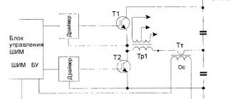
Novan on changing the feed speed of the electrode wire depending on the voltage on the arc. If for any reason the arc length increases, the arc voltage also increases. The wire feed motor will begin to rotate faster, increasing the feed speed. The arc length, and therefore its voltage, will be restored to its original value. And, conversely, when the arc length decreases, the feed speed slows down and the blowing parameters are restored again. Equality of speeds Vt - Vn is ensured by changing the feed speed of the electrode wire. In Fig. Figure 11.4 shows a simplified diagram of automatic control of the arc parameters of the ADS-1000 automatic welding machine. The electric motor (DG) of the feed mechanism of the welding head is powered by direct current from a special generator
F and s. 11.4. Electrical circuit for automatic air control |
(GDG), which has two excitation windings connected in opposite directions. Independent winding / is powered by an external current source and creates a constant magnetic flux Fn, independent of the arc voltage. Winding II of the generator is connected to the arc through a rectifier (B) and creates an alternating magnetic flux Fr dependent on the arc voltage is always greater than the magnetic flux Fn. We obtain the resulting magnetic flux Фр,., = Фд - Фн. The generator (GDG) will supply a voltage of such polarity and value to the motor armature (DG) that the motor rotates in the direction of feeding the wire into the welding zone at a speed that maintains a constant arc length and voltage. The pre-required arc voltage is set by a potentiometer (RID) in the independent winding circuit. At idle, the magnetic flux FP will be maximum. The resulting magnetic flux Фрп will also be maximum. The head motor will drive the electrode down at high speed. When the electrode is short-circuited with the product, the voltage between them will become zero, the magnetic flux in the arc winding will disappear and the resulting flux Fr,, = - Fn. This means that a voltage of the opposite polarity will be applied to the motor armature (DG) of the head and the motor will begin to rotate in the direction of raising the electrode wire upward. An electric arc will be initiated. As the length of the arc increases, its voltage will increase, and the magnetic flux Ф;1 will also increase. At a certain arc voltage, the magnetic fluxes Fl and Phi will become equal and the electric motor will stop. As the electrode wire melts, the arc voltage will continue to increase, the magnetic flux Fd will become greater than the magnetic flux Fn, the polarity will change and the head motor will again begin to feed the wire down into the arc burning zone.
If for some reason the arc is shortened, its voltage will decrease, as a result of which the resulting magnetic flux and generator voltage (GDG) will decrease. The arc voltage, and therefore the voltage supplied to the armature of the head motor, will decrease. The electric motor will begin to rotate more slowly, the feed speed of the electrode wire will decrease, and the length of the arc, and therefore its voltage, will increase to the values initially set by the potentiometer (RID). In this way, the equality of speeds will be restored: K, = Vlr And, conversely, if for some reason the length of the arc increases, the arc voltage will also increase, the magnetic flux Fd will increase, and therefore the magnetic flux Mills. This will lead to an increase in voltage supplied to the armature of the head motor, which will increase the speed and feed the wire into the welding zone at a higher speed. The disturbed balance K = K will be restored again. Thus, the electrode feed speed depends on the arc voltage,
i.e., from its length. This scheme ensures not only the maintenance of a stable arc, but also its automatic ignition at the beginning of the welding process.
In automatic tungsten electrode welding machines, the regulating effect is the forced restoration of the previously set (reference) arc voltage. This is done by changing the length of the arc gap by moving the electrode in height. When the arc voltage increases, the electrode automatically lowers, and, conversely, when the arc voltage decreases, the electrode rises. For this purpose, welding heads are equipped with a special automatic arc voltage stabilization system.
