An induction cooker is capable of heating metal cookware through induced eddy currents from a high-frequency magnetic field.
The standard circuit of an induction cooker is usually represented by an induction coil and a frequency converter, as well as an electronic control unit equipped with temperature sensors.
Introduction
Induction cookers are relatively new equipment, but already extremely popular among domestic consumers.
A special feature of such stoves is their ability to heat only the bottom of the cookware.
In conventional electric stoves, the burner that is turned on initially heats up.
Before choosing such equipment, it is important to familiarize yourself with the advantages of operation, as well as take into account some of the design disadvantages of an induction cooker.
The main advantages are presented:
- faster heating and cooking process, which takes several times less time than when using a traditional electric stove;
- no burning of food that may fall on the hob during cooking, which is due to the low temperature of the burner;
- reduction in electrical energy consumption due to very rapid heating of the kitchen utensils used;
- ease of use due to the ability to adjust the cooking mode on different stoves.
The advantages also include safety of operation, which is especially important for families with small children, pensioners or people with disabilities.
Induction cooker in the kitchen
Operating disadvantages in such modern equipment are also present and, despite the fact that they are minimal, they should be taken into account when choosing a model:
- turning on induction equipment at full power can create an increased load on the electrical network;
- for cooking on this type of stove, only special kitchen utensils with a ferromagnetic bottom should be used;
- Some models are characterized by the presence of a single high-frequency generator, which adversely affects the power level when all burners are turned on simultaneously;
- The hob surface is fragile, so during the entire period of operation it is necessary to exercise some caution.
As practice shows, the operation of models belonging to the economy class price category is often accompanied by irritating noise and a kind of humming.
It is important to remember that induction cookers are capable of creating fairly high electromagnetic radiation and can have a negative effect on household appliances installed at a short distance.
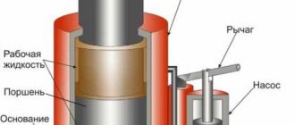
Induction cooker diagram
In accordance with the heating circuit, the electric current that flows from the electrical network to the coil undergoes a transformation into a magnetic field that generates eddy currents.
As a result of the interaction of the ferromagnetic bottom with the induction current, a circuit is formed, and the resulting thermal energy warms up the kitchenware used and its contents.
The glass-ceramic surface of the stove covers an induction coil with an electric current flowing at a frequency of 50 kHz. The standard equipment layout is relatively complex, and can have very significant differences depending on the model. The basis is represented by a generator, a driver using medium-power transistors and an output bipolar transistor, which has an insulated gate and controls the inductor coil.
The operation scheme of an induction cooker is reflected in the maintenance rules and operating features of such equipment, and must also be taken into account when choosing kitchenware, which must be made of special materials with ferromagnetic properties.
Electrical diagram of an induction cooker
The most complex structural element is the electronic control unit, through which it not only turns on, but also regulates the power level of the generator. Modern models are characterized by the presence of an infrared sensor device that effectively controls the cooking process. After the cookware is removed from the hob, the stove automatically turns off.
You cannot use copper, glass, ceramic or aluminum cookware, and the surface of an induction cooker can only be cleaned using special products that do not have abrasive effects.
Simple induction cooker
The other day, I was leafing through the works of my comrades and came across an article from the author of TOOZPICK, dated 03/31/2018.
It offered the option of heating a room using an industrially manufactured induction cooker. And the thought came, why not consider how to make this very thing, a stove, yourself? In addition, the author whom I propose explained in detail in the film how this can be done. Or rather, I propose for your consideration two projects on this topic. The content of the projects is similar both there and heating. Minor differences in circuits. So, let's begin.
The proposed version of the stove is very simple, I can’t even believe that it works.
Two field-effect transistors 50N06, two resistors 220 Ohm 1 W, two diodes UF4007, 4 capacitors 0.33 uF 1000 V and two chokes (inductors) 40-100 mH.
For assembly, two pieces of wire were stripped of enamel and four capacitors were soldered to them in parallel, resulting in a monolith onto which field-effect transistors were first soldered on both sides using a hinged method.
Then we soldered two chokes, on the terminals of which a jumper was installed, as well as on the legs of the field-effect transistors.
Resistors and diodes were soldered to the bases of field-effect transistors.
Radiators were used to cool the transistors
To supply power, we solder a common wire to the source of one of the transistors. This will be the negative terminal, and the positive one will be from the connection of the chokes. The electrical part is complete, all that remains is to wind the coil and you can test it. On ordinary cardboard, after it has been pierced with a wire, on one side the wire is bent, and on the other side it is wound with a snail of 9-10 turns. To prevent the rings from bridging, they are glued to cardboard. The ends of the coil are soldered to the ends of the capacitors.
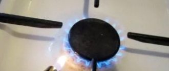
To see. how the assembly works, the author wound a coil of 20 turns with a wire thinner than the main coil and hung a car lamp on its ends. The circuit was powered by 12 v.6A. When the coil with the lamp was brought close to the main coil, the lamp flared to full intensity.
Next, a metal plate was placed on the inductor, a glass of water was poured into it and a thermometer was placed. The voltage was connected to 24 v 10A. to speed up the process. The water boiled in four minutes. At this voltage, the author used forced cooling; the coil itself does not heat up.
We boiled some water for tea, that is, the model is working, you can make soup, and what about frying, you can try to cook something. Let's return twelve volts. Put a piece of butter and as soon as it melts, pour in the broken egg. The scrambled eggs begin to scramble and give you an appetite. Everything is working. Generation is approximately 60 kHz
Well, with this assembly everything is clear, the second one is the same, only the diagram has different details.
Transistors 2 pcs. IRFZ44N, resistors 460 Ohm - 2 pcs, 10 kOhm - 2 pcs, diodes UF4007 - 2 pcs, zener diodes 10 V - 2 pcs, capacitor 0.47 μF 100v, stabilizer chip LM7812 and inductor inductance 1000 mH.
The coil is wound turn to turn with a snail, thick insulated wire 1.5 sq.. and consists of 18 turns with a tap from the middle.
I really liked the author’s statement when he whispered to us that the board was made to order, shared the top view and did not show anything about the tracks inside. And he suggested that those who wanted to assemble it using a hinged method or on a breadboard. After a set of parts we can see the completed assembly.
Powered by a powerful unit or battery. With this author, we cannot trace the assembly as in the first version, it is beautiful, neat, but not interesting. One good thing is that after ten minutes the water in the bowl began to boil.
If you believe the video stories, a thought comes to mind. What if these devices are powered directly to the solar panel, or at least through a buffer battery?
Well, in sunny weather during a hike or a car rally, you can save gas and not think about firewood. And be with hot food. Source
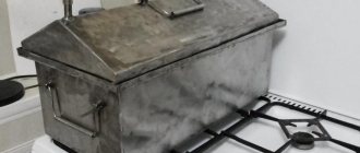
DIY making
The power circuit of a standard induction cooker can vary significantly depending on the design features of the modification, but most often it is presented:
- a ferrite torus, which is placed on the network wire and suppresses common-mode interference;
- standard fuse;
- a capacitor that filters impulse noise that occurs during operation;
- a resistor that is activated after the mains power is turned off;
- a rectifier designed for power ratings and effectively protecting the device from overvoltage;
- wire shunt;
- filtering system for impulse noise;
- a capacitor that allows you to return energy from the oscillatory-inductor circuit to the intermediate part with constant current values;
- a resonant capacitor that provides continuous current after the transistor is blocked;
- an induction device, which is focused on transferring heat from the surface to the bottom of the kitchenware used;
- a transistor that converts direct current into variable indicators;
- a resistor to fix the transistor after disconnection;
- a resistor to suppress high-frequency current indicators;
- rectifier for voltage in the electrical network;
- a current controller that prevents the possible occurrence of an overload;
- collector voltage controller.
Budget models contain only basic structural elements, which affects the functionality of such a device.
Self-manufacturing of a simple induction cooker requires strict adherence to all standards, which will make the operation of such a device completely safe. A significant difficulty in the process of constructing a stove arises at the stage of selecting high-quality material to create the base of the hob.
DIY induction cooker - diagram
Such a material must be distinguished by the ability to correctly conduct electromagnetic radiation, not conduct current, and withstand high temperatures.
Factory-made household cooking equipment, which includes all modern induction cookers, is made using quite expensive ceramics.
It is for this reason that making your own induction hob at home is associated with certain problems in choosing a worthy alternative to a ceramic surface.
A heat gun is good because it quickly distributes heat. Making a heat gun with your own hands is quite simple.
You will learn how to calculate heat loss at home from this information.
Recommendations for making a pellet burner with your own hands can be found here.
DIY induction heater, working diagram of the device
An induction heater is an indispensable thing for blacksmiths, turners, mechanics and home craftsmen. With its help, you can always easily and quickly heat and even melt metal; you do not need expensive coolants such as coal and gas; you just need to connect electricity to the device. Non-contact heating of the metal occurs with high-frequency currents, scientifically called radio-frequency waves. The device is widely used for heat treatment, hardening and bending of parts, non-contact melting, soldering and welding of metals. In jewelry making for heat treatment of small parts. In medicine for disinfection of medical instruments. In a car repair shop, a mechanic heats up rusted nuts. The inductor is also installed in induction boilers used for heating residential premises.
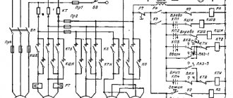
This picture shows a working diagram of an induction heater, which you can easily make with your own hands.
Download induction heater diagram
The device consists of a high-frequency master oscillator assembled on two powerful field-effect transistors. The operating voltage of the generator depends on the power of the installed field-effect transistors. With IRFP250 transistors, the device can be powered with voltage from 12 to 30 volts. And if you install IRFP260 transistors, then the supply voltage can be raised from 12 to 60 volts.
The power of the inductor will increase noticeably, the heating temperature of the metal will rise to more than 1000 degrees, which will allow the metals to melt. During operation, the transistors will become very hot, so they must be installed on large radiators and a powerful fan. At idle, the inductor consumes at least 10A, and in operating condition at least 15A; accordingly, a very powerful power supply of at least 20A is required.
This picture shows the PCB of an induction heater.
Download the printed circuit board of the induction heater in lay format
You will also need 10K resistors R1, R2 with a power of 0.25 Watts. Resistors R3, R4 with a resistance of 470 Ohms of at least 2 Watts. Diodes D1, D2 ultra-fast UF4007 or other similar ones for a maximum current of up to 1A. Zener diodes VD1, VD2 with a power of at least 5 Watts with a stabilization voltage of 12V, for example 1N5349 and others. I pulled out chokes L1, L2, 27x14x11 mm in size, yellow with a white stripe, from computer power supplies. For each choke you need to wind 25 turns of copper wire with a diameter of 1 mm, preferably in varnish insulation; if you can’t find it, a single-core wire in PVC insulation will do; it does not greatly affect the speed.
Metal film capacitors C1-C16 0.33 uF 630V, connected in parallel in 4x4 rows, there are only sixteen pieces in the block. It’s better not to install it with a lower operating voltage; they will get very hot. Leave a small distance between the condensers for good cooling by air flow.
I decided to glue the chokes with silicone sealant so that they would not dangle.
I made an important part of the heater, the inductor, from a copper tube with a diameter of 6 mm and a length of 1 meter. You can buy one at any auto store like “Gazovshchik” and where they sell gas equipment for cars. We wind the copper tube onto a piece of polypropylene pipe with an outer diameter of 40 mm; such a pipe is used in plastic heating. We make five turns, the distance between the top edge of the first turn and the bottom edge of the fifth turn should be 40 mm. We bend the ends of the pipe as in the figure and attach them to the radiators using two terminal blocks for a wire with a cross-section of 16 mm².
During operation, the inductor will become very hot from the hot part, which can lead to damage to the copper tube, so cooling must be done. I put silicone tubes on the ends of the copper tube and connected the car windshield washer pump. I bought a pump from a VAZ 2114 and silicone tubes at a car store. The result was a normal water cooling system.
To cool the radiators and capacitor unit, I installed a powerful fan from the processor. For power supply from 12 volts, such cooling is quite enough. If you want to increase the voltage from 12 to 60 volts in order to get maximum power from an induction heater, install more powerful radiators and a more efficient fan, for example from the interior heater of a VAZ 2107. It is advisable to make a metal curtain that protects the heated part and the copper inductor from the flow of cold air forced by the fan .
Since the induction heater consumes a large current of about 20A, all traces on the PCB should be reinforced with copper wire soldered on top.
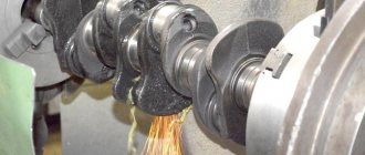
And now the most interesting part... I tested the induction heater using a twelve-volt car battery. I simply do not have another power source capable of delivering high currents. The blade of a stationery knife became red hot in 10 seconds. And this is a good result, considering that the inductor is powered by only twelve volts!
Friends! If you want to assemble an induction heater with your own hands. My advice to you... Immediately install IRFP260 field-effect transistors, large radiators and a powerful fan from the VAZ 2107 interior heater; to power the inductor, be sure to use a powerful power source, preferably from 24V to 60V with a current of at least 20A.
Radio components for assembling an induction heater
- Transistors T1, T2 IRFP250 are better than IRFP260 2 pcs.
- Resistors R1, R2 10K 0.25W 2 pcs. R3, R4 470R 2W 2 pcs.
- Ultrafast diodes D1, D2 UF4007 2 pcs. or similar
- Zener diodes VD1, VD2 for 12V 1W 1N5349 or similar 2 pcs.
- Capacitors C1-C16 0.33mf 630V 16 pcs.
- Chokes from a computer power supply are yellow with a white stripe, size 27x14x11 mm, 2 pcs.
- Terminal block for wire with a cross section of 16 mm² 2 pcs.
- Copper wire in varnish insulation d=1 mm length 2 meters
- Copper tube d=6 mm, length 1 meter
- The bigger the better the radiator 2 pcs.
- Windshield washer pump from VAZ 2114 1 pc.
- Silicone tube 2 meters
- The more powerful the fan, the better. I recommend from the interior heater VAZ 2107 1 pc.
Friends, I wish you good luck and good mood! See you in new articles!
I recommend watching a video on how to make an induction heater with your own hands