Types of work performed on drilling machines
Drilling machines perform drilling, reaming, countersinking, reaming, countersinking, counterbore, processing stepped holes and cutting internal threads. By drilling (Fig. 16, a) through and blind holes are obtained. By drilling (Fig. 16, b) the diameter of the previously drilled hole is increased.
Countersinking (Fig. 16, c) also increases the diameter of the hole, but compared to drilling, countersinking allows for greater accuracy and processing productivity.
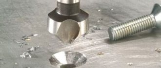
Countersinking can be used to process holes made in a workpiece by casting or pressure. Reaming (Fig. 16, d) is a finishing operation that ensures high hole accuracy. Reaming is used to process cylindrical and conical holes after countersinking or boring. Countersinking (Fig. 16, e, f) processes cylindrical and conical recesses for the heads of bolts and screws. To ensure perpendicularity and alignment of the machined surface to the main hole, the cutting tool (countersink) is equipped with a guide cylinder (Fig. 16, e).
Countering (Fig. 16, g, h) is used to process the end support planes for the heads of bolts, screws and nuts. The perpendicularity of the machined end surface to the main hole is ensured by the guide cylinder of the cutting tool (counterbore). Using a centering drill (Fig. 16, i) the center base holes in the shafts are processed. Internal threads are processed with taps (Fig. 16, j). In this case, the feed speed must be equal to the thread pitch (So = h). Complex surfaces are processed with a combined tool (Fig. 16, l).
Rice. 16. Schemes for surface treatment on drilling machines : a – drilling; b – drilling; c – countersinking; d – deployment; d, f – countersinking; g, h – countersinking; and – processing of basic center holes; k – cutting internal threads; l – processing of complex surfaces
Rice. 17. Processing of precise conical holes : a – countersinking with a stepped countersink; b – rough deployment; c – final deployment
The processing scheme for a precise conical hole is as follows: drilling a cylindrical hole; countersinking with a stepped conical countersink (Fig. 17, a); reaming with a conical reamer with chip separating grooves (Fig. 17, b); deployment with a smooth conical reamer (Fig. 17, c).
Processing workpieces on drilling machines
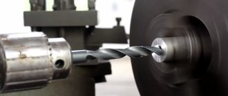
When processing on vertical drilling machines (the most common), the workpiece remains motionless, and the drill inserted into the machine spindle makes rotational and translational movements.
The following are used as RI:
1. Drills,
2. Countersinks,
3. Sweeps,
4. Taps.
When drilling, you can get holes with a diameter of 0.25 - 80 mm. If the drill diameter is up to 20 mm, then it may have a cylindrical shank. Drills with a diameter of 6 – 80 mm have a conical shank. Drills are made with 2 flutes from high-speed steel R9, R12, R18, R6M5, R6M5K5, low-alloy steel - 9ХС, carbide steel VK6, VK8, VK10, VK15, etc. if the diameter of the resulting hole in a solid material exceeds 30 mm, then processing is carried out sequentially 2 - with drills.
By drilling you can get a hole of 12 quality and Rz = 40 µm.
Countersinking is performed after drilling or rough boring. The allowance for countersinking is about 0.5 - 2.0 mm per side, or (0.05 - 0.1) dz.
The cutting edge of countersinks is made of high-speed steel or hard alloys. The shank shape is cylindrical and conical.
According to the shape of the cutting part, there are cylindrical, stepped and conical countersinks. Conical countersinks can be used after making a preliminary hole with a drill bit.
Countersinks are made of high-speed steel R9, R12, R18, R6M5, R6M5K5, low-alloy steel - 9ХС, carbide steel VK6, VK8, T5K10, T15K6, etc.
By countersinking you can get a hole of 10 quality and Ra = 10 µm.
It is necessary to distinguish between countersinking, countersinking and countersinking.
Countersinking -
processing of workpieces in order to obtain conical or cylindrical recesses, supporting planes around the hole and chamfering the center holes (Fig. 3.52, a).
Countersink -
axial multi-blade tool for machining the conical entrance section of the hole.
Like countersinking, countersinking is a type of countersinking.
Countering -
processing the surface of the workpiece around the hole. It is intended to form planes for a screw head, washer, thrust ring, etc. (Fig. 3.52, b).
Countering -
an axial multi-blade tool for processing the cylindrical and (or) end section of a workpiece hole. The counterbore has a lower smooth guide part inserted into the hole around which the processing is carried out, which ensures mutual perpendicularity of the resulting surface and the axis of the hole.
Reaming is performed after countersinking (sometimes after drilling) or fine boring. A reamer is a measuring tool (sharpened to a specific size). The allowance for unfolding is 0.08 - 0.2 mm per side, or about 0.005dр. the shape of the cutting part (the resulting hole) is similar to countersinks.
Reamers are made for roughing, semi-finishing and finishing. Reamers have an even number of teeth. According to the design of the shank, reamers with a conical and cylindrical shank are divided.
Reamers are made from high-speed steel R9, R12, R18, R9K5, R6M5K5, low-alloy steel - 9KhGS, carbide steel VK6, VK6M, T15K6, T5K10, etc.
By reaming you can get a hole of 6-9 quality and Ra = 0.63 µm.
Using a tap you can get a thread in a hole of M1 - M52 mm. hand taps are made of carbon steel U10, U12, machine taps are made of high-speed steel.
Processing workpieces on milling machines
When processing on vertical and horizontal milling machines (the most common), the workpiece remains motionless, and the RI inserted into the machine spindle makes rotational and translational movements.
The following types of cutters are used as RI:
1. Cylindrical,
2. End
3. End
4. Disk.
Milling cutters with carbide inserts have 1.5-2 times higher durability and can reduce cutting time by 20-25% and the number of cutters used in production compared to conventional cutters made of high-speed and tool steels.
The variety of cutter designs used in production makes it necessary to classify them according to a number of characteristics.
Based on the material of the cutting part, cutters are divided into carbon, high-speed and carbide.
Based on the shape of the cutting teeth, cutters with pointed and backed teeth are distinguished (see Fig. V.2).
According to the direction of the cutting teeth, cutters are divided into straight teeth with helical (see Fig. V.3) or spiral teeth.
According to their purpose (the nature of the work performed) and the location of the blades, cutters are divided into cylindrical (Fig. V.6, a) and end mills (Fig. V.6, b), used for processing planes; double-sided disk (Fig. V.6, c) for milling shoulders and three-sided disk for milling grooves (Fig. V.6, d); slotted (Fig. V.6, e) and end (Fig. V.6, f), used for processing small-sized planes, grooves, ledges, surfaces of curved contours for flat-shaped products, etc.; angular (Fig. V.6, g) for processing corner grooves and grooves and shaped (Fig. V.6, h) for processing shaped surfaces.
According to the method of fastening on the machine, cutters are divided into attachment cutters, mounted on a mandrel, and end cutters, secured with a shank.
According to their design, cutters are divided into solid ones, the teeth of which are integral with the body; prefabricated - with inserted teeth (in the form of knives or directly cutting plates); composite, for example, made up of two halves and a spacer between them to restore the original length of the cutter after resharpening.
Based on the size and number of teeth, cutters with small and large teeth are distinguished. Fine-toothed cutters are usually called cutters whose number of teeth z is greater than 1.5, and coarse-toothed cutters are called cutters whose number of teeth z is less than 1.5, where D is
cutter diameter, mm. Large-tooth cutters include cutters with insert knives and are used for rough and semi-finish milling. Fine-tooth cutters are used for finishing and finishing milling.
The number of teeth for fine- and coarse-tooth cutters of each type, depending on their diameter, is established by state standards.
In some cases, it is advisable to use one- and two-flute cutters, i.e. prefabricated cutters, in the body of which one or two diametrically located teeth are fixed. Such cutters, sometimes called flying cutters, are usually used for processing single shaped profile parts, as well as for milling some non-ferrous metals and light alloys. Flying cutters are widely used in repair production.
The values of cutter diameters and widths are normalized. They form a geometric series with the progression denominator f = 1.26. The outer diameters of standard cutters are assumed to be: 16, 20, 25, 32, 40, 50, 63, 100, 125, 160, 200, 250 mm, etc. up to 630 mm. The normal width of cylindrical cutters is a range of sizes 50, 63, 100, 125 mm. The cutter holes are provided with a longitudinal keyway for transmitting torque from the spindle using a key and an internal groove (in cutters with a width of more than 24 mm).
The shanks of end mills with a diameter of less than 20 mm are made cylindrical; For milling cutters of larger diameter, the shanks are made with a Morse taper or metric taper, standardized according to GOST 24644-81.
4.4. abrasive processing
Abrasive machining is the process of processing materials by cutting. The metal layer (allowance) is removed from the workpiece as a result of cutting, carried out with an abrasive tool with a large number of micro-cutters - abrasive grains.
The following types of processing are classified as abrasive.
Grinding -
processing with a rotating tool - a grinding wheel.
The rotation of the circle is the main cutting movement and is carried out at a speed of 10-100 m/s. Grinding is used to remove a certain layer of metal (allowance), give the workpiece the required shape, obtain the dimensions and shape of the part specified in the drawing, as well as the required surface roughness. Grinding provides 5-7 grades, and the roughness parameter Ra =
1.2 - 0.1 microns.
Finishing -
processing, carried out, as a rule, after grinding and aimed at achieving the highest accuracy of the dimensions and shape of the part, as well as high surface quality.
When finishing, the tool and the workpiece in most cases simultaneously perform several movements (rotational, reciprocating, oscillatory) at a speed of 0.1-3 m/s. Finishing is used as a finishing technological operation in the manufacture of the most precise parts. Finishing provides 0.1-4 quality, and roughness parameter Ra
= 0.10-0.01 microns.
Polishing -
processing of parts in order to reduce roughness, obtain a mirror shine, and also remove the defective layer.
As a result of polishing, micro-irregularities on the surface of the part acquire a smoothed, rounded shape, which significantly increases the reflectivity of the surface. The tool used is a disk with a working end surface. Polishing produces shiny surfaces with a roughness parameter Ra
= 0.1-0.04 microns.
Segment -
dividing a workpiece, such as a rod, into parts using a special cutting wheel. Cutting is also used to remove sprues and profits from casting blanks. The productivity of abrasive cutting, especially at high (80-100 m/s) speeds, significantly exceeds the productivity of other types of cutting (mills, circular saws, etc.).
Finishing processing -
processing, the purpose of which is: removal of the surface defective layer of metal; removal of burrs after cutting and flash after stamping and precision casting; rounding of edges; preparation of surfaces for coating; removal of scale formed during heat treatment; giving parts a marketable appearance. In most cases, finishing is carried out by exposing the workpiece to a flow of free abrasive grains.
Types, elements and geometry of axial tools
Drills can be spiral, feather, for deep drilling (auger, ring, gun, cannon), centering and combined (special).
A twist drill (Fig. 18, a) has a working part 9 and a shank 7. The shank is used to secure the drill in the working fixture of the machine and is cylindrical or conical. The conical shank is equipped with a foot 6, which protects it when the drill is knocked out of the machine spindle. The working part of the drill is made of tool steel or with brazed carbide plates. It carries out the cutting process, shapes the surface of the hole being machined, removes chips from the cutting zone and guides the drill during processing.
The working part 9 consists of a guide 8 and a cutting part 10. The guide part has two helical grooves 5, necessary for removing chips from the cutting zone, and two ribbons 4, necessary for guiding the drill. The cutting part has two main cutting edges 11, formed by the front 1 and the main rear 3 surfaces. The main cutting edges are connected at an angle of 2φ by transverse edge 2. The thickness and width of the cut layer, the ratio between the radial and axial components of the cutting force and the temperature in the cutting zone depend on the value of the angle 2φ.
The rake angle γ is measured in the main cutting plane running perpendicular to the main cutting edge. The clearance angle α is measured in a plane passing through the point of the main cutting edge parallel to the axis of the drill. The angle values change from the center of the drill to its periphery: from the periphery of the drill to the center, the angle γ decreases, and the angle α increases. The rake angle of the transverse edge is negative and equal to approximately 60°, therefore, the transverse edge crushes and scrapes the material being processed, which sharply increases the cutting force. To reduce the influence of the transverse edge on the cutting process, it is rational to process large-diameter holes in two stages: drilling the hole with a drill of a smaller diameter and reaming the hole with a drill of the required diameter. The drill strip serves to center the drill on the machined surface and makes it possible to resharpen it multiple times.
The width of the bands of industrial drills is 0.2–3 mm. Along the ribbon, the drill has a reverse taper of 0.03–0.12 mm per 100 mm of length.
Feather drills (Fig. 18, b) are much simpler and cheaper to manufacture than twist drills, and their rigidity is somewhat higher. They are designed for processing relatively short holes. The working part of the drill is made in the form of a thin plate with two cutting edges located relative to each other at an angle of 2φ, which is equal to 116–118°.
Rice. 18. Drills : a – spiral: 1 – front surface; 2 – transverse edge; 3 – main rear surface; 4 – ribbon; 5 – helical groove; 6 – foot; 7 – shank; 8 – guide part; 9 – working part; 10 – cutting part; 11 – main cutting edge; b – feather: d – drill diameter; α, γ, φ – cutting angles; c – screw
Auger drills (Fig. 18, c) are made with a large angle of inclination of the helical grooves (up to 60°), which allows drilling holes with a length-to-diameter ratio of up to 30 in one pass without periodically removing the drill from the hole to remove chips.
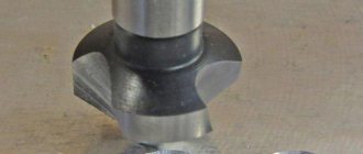
Countersinks, countersinks and reamers are multi-edged dimensional axial cutting tools designed for preliminary or final processing of holes obtained in previous operations. The common structural element of these cutting tools is the working part 3 (Fig. 19, a, f) and the connecting part. The connecting part is made in the form of a cylindrical or conical shank (end tool) or a conical or cylindrical hole with a transverse groove at the end (attached tool).
According to the design and material used, these tools are divided into solid ones made of high-speed steel; equipped with brazed plates made of hard alloy; prefabricated with mechanical fastening of high-speed or carbide knives; with mechanical fastening of multifaceted carbide inserts.
Rice. 19. Countersinks, counterbores, countersinks and reamers : a – countersink; b, c – countersink; d – one-sided reverse counterbore; d – double-sided counterbore; e – scan; 1 – cutting part; 2 – calibrating part; 3 – working part; 4 – axle; d – true diameter of the reamer; f – ribbon width; α, γ, φ, ω – cutting angles
With the help of countersinks (Fig. 19, a) cylindrical holes obtained by drilling, casting, forging, stamping are processed in order to give them a more regular geometric shape, increase dimensional accuracy and reduce surface roughness. The cutting part 1 (Fig. 19, a) of countersinks is characterized by the angle of inclination of the chip flutes or knives ω, the front and rear angles, the main angle in the plan and the width of the ribbon f. Typically, countersinks have a right-hand flute angle, which provides good chip removal and a positive rake angle. Countersinks for processing blind holes are made with a cutting edge perpendicular to the axis of the countersink (φ = 90°).
The leading angle affects the thickness and width of the cut layer and, accordingly, the components of the cutting force and the conditions for heat removal from the corner points of the tool tooth.
To process the supporting surfaces for mounting screws, countersinks with a replaceable pin 4 are used (Fig. 19, b). To process conical surfaces for the screw head and to machine center holes, countersinks are used, shown in Fig. 19, c.
For trimming ends and bosses, one-sided (Fig. 19, d) and double-sided (Fig. 19, e) counterbores are used.
A reamer (Fig. 19, e) is a finishing axial tool that allows you to process precise cylindrical and conical holes on drilling, turning, boring machines or manually.
Cylindrical reamers make it possible to process holes with an accuracy of 6–11 grades, with a roughness Ra of 0.8–1.6 µm. An important parameter of reamers is their working diameter. Conical reamers are designed for preliminary and finishing machining of conical holes with a taper of 1:50; 1:30; 1:20; 1:16. A special feature of conical reamers is the absence of a calibrating part. The main cutting edges are cone-shaped along the entire length of the teeth. They are sharpened on the front and back surfaces. Along the cutting edges, along the cone, a narrow strip with a width of no more than 0.05 mm is left, which allows you to accurately maintain the conical surface and reduce the roughness of the treated surface. The front and rear angles are 5 and 10°, respectively.
Combined tools are used to process holes with complex configurations.
Depending on the purpose and shape of the holes, combined tools are made up of drills, countersinks and reamers, working either in series or in parallel.
Cutting modes when drilling
The drilling process takes place under more severe conditions than turning. During the cutting process, it is difficult to remove chips and supply coolant to the cutting zone. The chips additionally rub against the surface of the drill grooves, and the drill strips rub against the machined surface. The amount of heat released during cutting is mainly absorbed by the cutting tool and the workpiece. This is especially noticeable when drilling holes in materials with a low heat transfer coefficient (for example, plastics, concrete). When processing these materials, up to 95% of the generated heat is absorbed by the drill, and if cooling is not used, the cutting edges of the drill melt.
The cutting speed along the cross section of the drill is not constant; it decreases from the periphery of the drill to its center. Consequently, compared to turning, when drilling, the deformations of the cut layer and friction chips are increased (pairs “drill - workpiece”, “chips - drill”, “chips - workpiece”); it is necessary to reduce the cutting speed by 30–60%.
When drilling, the cutting speed V, m/min, is taken to be the peripheral speed of the most distant point of the cutting blade. When assigning the feed speed, a distinction is made between the minute feed Sm, the feed per revolution So and the feed per tooth Sz. The cutting depth t, mm, is taken to be half the diameter of the drill (when drilling a hole in a solid material) or half the difference between the diameter of the machined hole and the workpiece (when drilling, countersinking and reaming):
V = πDn / 1,000; S m= nSo = nSzt; tc= 0.5D; tp= 0.5(D – d),
where D is the outer diameter of the drill (the diameter of the hole being machined), mm; n – machine spindle rotation speed, rpm; z – number of teeth; d – diameter of the hole in the workpiece, mm.
Metal processing by drilling: basic information
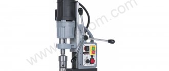
Drilling processing is carried out on special drilling machines, where the workpiece is rigidly fixed, and the cutting tool rotates and at the same time moves translationally along the axis of the hole drilled in the workpiece (this movement is called feed).
There are vertical drilling and radial drilling machines. The former are used for drilling holes in small workpieces, which, during the setting process, are moved along the table so that the axis of the drill and the axis of the future hole coincide. To work with heavy and large workpieces, radial drilling machines are used. On them, the workpiece is immediately rigidly fixed on the table, and the machine spindle is installed in the desired position. Work performed on drilling machines:
- drilling;
- deployment;
- countersinking;
- thread cutting.
Cutting tools used for processing parts on drilling machines:
- drill;
- sweeps;
- countersinks;
- taps (for cutting threads).
The main cutting tool when drilling parts is a drill. Typically, twist drills are used for this purpose, consisting of a working part, a neck and a shank. The working part, in turn, consists of two parts - cutting and centering. The cutting part has two cutting working edges connected to each other by a bridge. The centering part has a pair of screw strips that act as guides during the process of drilling metal, as well as two spiral grooves through which cutting fluid is supplied and chips are discharged. The shank can have a conical or cylindrical shape. The first option is intended for fastening the drill in the spindle using adapter sleeves, the second option is for fastening it in the chuck. The drill neck carries a masking, where, among other parameters, the diameter of the drill and the material of its cutting edge are indicated.