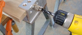
Drilling technology
The process involves sequential removal of a layer of metal in a circle of a given diameter using a cutting tool. Drilling metal combines two types of motion - rotational and translational. To obtain the required hole dimensions in metal workpieces, it is necessary to accurately maintain the following technological process parameters:
- cutting tool rotation speed;
- speed of horizontal or vertical movement (depending on the relative position of the workpiece and drill).
A hole in the metal is obtained with the specified parameters only if the preparatory and main operations are correctly performed, as well as the selection of the necessary equipment and cutting tools. Pre-drilling is often performed to obtain the required accuracy. It's called draft. The operation is performed with a reduced accuracy class. Next, the finishing operation is carried out using high-precision machines and tools for metal workpieces.
The process itself is carried out in various modes: using hand tools (drill or other tools), special drilling or metal-cutting machines.
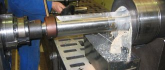
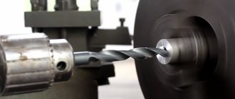
In all cases, different types of drills are used to obtain the required hole. On drilling machines, a chuck with a fixed drill rotates and is brought to the surface of the workpiece. On metal-cutting machines, the drill is fixed in the tailstock of the machine, and the workpiece rotates. The second method allows you to obtain higher accuracy of the hole and the walls of the resulting hole.
Depending on the tasks, the following types of drills are used for both methods:
- spiral (the most common type of this tool);
- with soldered plates on the cutting edge;
- centering;
- cannon;
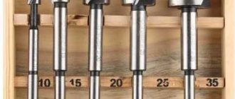
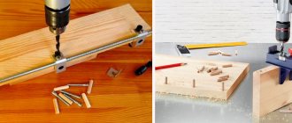
- feather (used for drilling holes in workpieces made of any type of wood).
Twist drills with their transverse edge exert pressure on the surface of the metal. This process accounts for more than 65% of the force during rotational and translational motion. At this moment, there is a significant increase in temperature of both the surface of the workpiece and the leading edge of the drill. Therefore, it is necessary to properly observe the thermal regime during the drilling process.
To speed up the cutting process in twist drills, so-called double sharpening is used. It allows you to work more efficiently on the hardest grades of metal, including cast iron. Such sharpening leads to an increase in chip width, the main angle decreases, and the durability and durability of the drill increases.
The technology for creating centering holes involves the use of special centering drills. They are made of tool steel and have a double-sided combined design.
Applying plates with increased strength to the cutting edge of the drill allows them to be used for drilling products made of cast iron, metal of increased hardness, dense building structures (concrete, stone, ceramic granite, etc.).
Feather drills differ in the design of the cutting edge. It is made in the form of plates. They are usually used to make holes in wood pieces. Sometimes special point drills are used to make holes in solid forgings and some types of castings.
Drilling modes
To obtain accurate and high-quality holes, it is necessary to comply with the modes and technologies of all operations. Drilling metal requires compliance with the following modes:
- selection of the required diameter and type of drill;
- cutting speed and depth;
- feed speed and accuracy (drill or workpiece);
- contact angle of the cutting surface with the workpiece;
- heating temperature of the workpiece and drill (providing cooling, if necessary).
The implementation of all modes allows you to obtain a hole in the metal that satisfies the conditions of the design documentation. Correctly selected mode increases processing accuracy and extends the service life of the cutting tool. Special tables have been developed for selecting drilling modes for metal products. They include precise parameters of cutting conditions. For example, knowing the steel grade and the diameter of the drill used, you can use the conversion table data to set the cutting speed. This will allow you to accurately adjust the spindle speed of the machine used. To do this, use a conversion table, which is applied to a special plate and fixed to the front panel of each machine.
In some cases, preliminary drilling is used. It prepares the rough hole for further processing (milling or reaming). If the workpiece is thick enough or it is necessary to obtain a deep hole, a step-by-step manufacturing mode is used.
Types of drills and devices for drilling in metal
The necessary equipment for drilling metal products are electric and hand drills, as well as drilling machines. The working part of such devices is a drill of different shapes:
- spiral;
- screw;
- crown-shaped;
- conical;
- flat;
- cannon;
- rifle;
- centering;
- stepped.
Each drill is individually marked, where the tip indicates the cross-sectional diameter and the type of alloy from which it is made. To drill a hole of the required diameter, you need a drill a few tenths of a millimeter narrower.
Drills are also classified by length:
- short;
- elongated;
- long.
Drilling in some materials may require a specially sharpened diamond-tipped drill bit. Twist drills may not be able to handle products made from thin sheet alloys. In some cases, to drill deep holes, the product must be fixed in a vice, stops, jigs, or corners with fasteners. This is done for safety reasons and to obtain high quality holes.
Types of holes and methods for drilling them
In the theory of metalworking, all holes are divided according to the following criteria:
- purpose;
- geometric dimensions and depth;
- degree of processing.
They are divided according to their purpose: for fastening two or more elements, subsequent threading, and inserting individual structural elements.
Based on the second criterion, the following types are considered:
- end-to-end;
- deaf (including deep);
- half;
- large diameter.
A special place is occupied by holes that are prepared for cutting internal threads. In this case, drilling and reaming of holes is carried out taking into account the future diameter of the screwed-in element with an external thread. For each hole, different drilling methods are chosen.
Since drilling is a mechanical cutting process of metal, the necessary processing methods should be selected to obtain the desired result. To produce through holes in parts, it is necessary to consider a system for fastening them, which will not allow damage to the surface located behind the part. It is most advisable to use a vice or clamps.
To make blind or half holes, it is necessary to provide an accurate stop of the drill, which will provide the required size. Drilling large holes requires the use of special equipment. If it is necessary to obtain holes of different diameters, you should select the required set of drills or use machines with numerical control. They will allow you to automatically replace the drill with a tool with a given diameter.
Equipment and accessories for drilling
A tool for drilling holes has been developed for each stage. At the preparatory stage, the following tools are used to accurately mark the location of the future hole. To do this, use: a core, a special template or a jig. The core is a well-sharpened rod made of durable tool steel. With its help, a depression is made on the surface of the workpiece, at the point where it is planned to drill. Once in this recess, the drill does not slip on the surface and accurate drilling is performed.
To increase productivity, mass production plants make special templates. They allow you to mark the locations of future holes in workpieces of the same type. Special templates are used for drilling on cylindrical surfaces. They are made from a steel strip bent at a right angle. A small hole is drilled on one of the surfaces, which will later allow a core to make a mark on the cylindrical surface.
To obtain increased marking accuracy, maintain the vertical position of the drill and maintain the specified distance, a tool called a jig is used between the holes. In addition, it is used when drilling thin-walled products for which strong mechanical impact is not possible (for example, hitting a core with a hammer).
In addition to these products, tools and devices are used that allow drilling with a drill with its rigid fixation. For this purpose I use:
- guide clamp;
- holding stand;
- jig to direct the movement of the drill.
The first two devices are made for a specific electric drill design. The jig allows you to accurately guide the drill to the location of the future hole. It is successfully used for sizes not exceeding 20 millimeters. Therefore, when making large-diameter holes using a jig, preliminary drilling is performed.
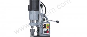
All these problems are easily solved by using drilling or lathes. Drilling machines are divided into three categories:
- universal;
- specialized;
- special.
They are classified according to the following criteria:
- table design;
- level of automation;
- number of available spindles;
- degree of accuracy;
- availability of additional features.
The first category of machines allows you to solve almost the entire range of problems in the production of holes. A serious limitation is the permissible distance over which the chuck with a fixed drill can move. This circumstance does not allow drilling to great depths. In this case, specialized machines are used. To increase labor productivity and increase the number of similar parts produced, special units are designed. They are able to perform a list of necessary operations with high accuracy and speed.
By design, such machines are available with one or more spindles. The design of the table is varied: regular, floating, lifting and others. The level of automation is determined by the way drilling operations are performed. The simplest machines are manual and mechanical. Automatic and numerically controlled machines are more advanced.
In addition to drilling machines, various lathes are used to solve these problems.
To make holes on a lathe, a drill is secured in the headstock spindle, and a workpiece is secured in the tailstock.
On lathes you can perform the entire list of operations related to making holes: drilling itself, drilling followed by reaming or countersinking.
Drilling and hole reaming
Purpose and tools. Drilling can produce holes with an accuracy of up to 12th grade and a roughness of Rz≥80 µm. Drilling increases the diameter of a previously drilled hole and, under certain conditions, increases its accuracy by approximately one grade.
Spiral drills are mainly used as cutting tools for the considered processing methods.
A twist drill (Figure 51) is a two-toothed cutting tool consisting of a working part, a neck and a shank. The working part includes cutting and guiding parts.
The working part of the drill has two chip flutes, the helical shape of which facilitates the exit of chips from the hole. To reduce friction on the walls, the holes in the backs of the teeth are lowered, and narrow guide strips are left along each of them. For the same purpose, a small reverse taper is provided on the guide part (0.03-0.12 mm for every 100 mm of length). To increase the strength of the drill, the depth of the chip flutes is gradually reduced towards the shank.
The cutting part has two cutting edges, which are connected in the center by a bridge (transverse edge). The front surface of the teeth is part of the helical surface of the chip flute, and the rear surface is the surface of the cone formed when sharpening the drill.
The shanks are made conical (for drills with a diameter of 6-80 mm) according to the dimensions of standard Morse tapers or cylindrical - for drills with small diameters up to 20 mm.
Drills are made of high-speed steel R6M5 and are also equipped with hard alloy VK8. The latter are intended for drilling cast iron and difficult-to-cut steels. In addition, in order to save expensive high-speed steels, the shanks of drills with a diameter of over 6 mm are made of structural steel and welded to the working part of the drill.
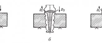
Fig 51. Twist drill:
a - parts; b -elements; in - main angles
To create favorable cutting conditions, the drill teeth are given a wedge shape, which is determined by the main angles “front γ, sharpening angle β and back α (see Fig. 51, c). The magnitude of these angles is not the same for different points of the cutting edges. The rake angle, due to the helical shape of the chip flute, has the greatest value (20-30°) at the periphery of the drill, and closer to its axis it gradually decreases to a negative value. The rear angle is also given a variable value by sharpening along the rear surfaces to compensate for its decrease in work: from 10-15° at the periphery to 20-25° near the axis.
The drill tip angle of 2φ has a significant influence on the cutting resistance (see Fig. 51, b). As this angle decreases, the overall cutting resistance increases, and the feed force acting along the drill axis decreases. For general purpose drills, the apex angle is within the range of 116-118°.
A significant disadvantage of twist drills is the presence of a bridge. Having a negative rake angle, it does not cut, but crushes the metal. For a properly sharpened drill, the jumper should be located towards the direction of the cutting edge at an angle ψ(psi) = 50-55°. Otherwise, the required value of the drill rear angle will not be maintained, since there is an inversely proportional relationship between these angles. For example, as the angle increases, the back angle a decreases and vice versa.
Figure 52. Template for controlling drill sharpening
Centralized sharpening of drills at enterprises is usually carried out on special drill sharpening machines. For universal work, this operation is often performed by the turner himself (similar to sharpening cutters) on simple sharpening machines.
During sharpening, the working part of the drill is held with the left hand, resting it on the tool rest, and the shank of the drill is supported with the right. With a little force, press the cutting edge against the working surface of the grinding wheel so that the edge initially occupies a horizontal position. Then the drill is slowly turned and at the same time fed forward onto the circle. After sharpening one back surface, the drill is turned and the other is sharpened.
Figure 53. Additional methods for sharpening drills
A high-quality sharpened drill must meet the following requirements: 1) apex angle 2φ = 116-118°; 2) the same length, straightness and symmetry to the axis of the cutting edges; 3) angle of inclination of the jumper to the cutting edges ψ= 50 -55°; 4) the absence of nicks, blockages, notches, burrs, burns, and cracks on the cutting edges.
Control of sharpened drills is carried out by external inspection and using a template (Fig. 52).
Figure 54. Adapter sleeve with drill shank inserted into it
To improve the cutting capabilities of drills with a diameter over 12 mm, in addition to the normal sharpening described above, it is recommended to perform double sharpening, sharpening of the bridge and ribbons.
Double sharpening (Fig. 53., a) is done along the rear surfaces of the drill by creating two additional sections on the cutting edges at an angle of 70-75° with a length of 0.2 drill diameters. Thanks to this, the overall length of the cutting edges increases, heat dissipation improves, the sharpness of the corners decreases and their strength and durability increases. In addition, thanks to the broken shape of the cutting edges, it is easier to separate wide chips and remove them from the hole.
The pointing of the jumper (Fig. 53, b) is carried out along the front surfaces of the teeth to reduce its length to approximately 0.1 drill diameter and increase the rake angle in this place.
The sharpening of the ribbons (Fig. 53, a, section A-A) is performed at a length of 1.5-4 mm near the corners of the drill. In these places, the width of the ribbon is reduced to 0.2-0.4 mm, which reduces friction in the most loaded area of the drill.
Installation of drills on the machine. On a lathe, drilling is done with a non-rotating drill, which is fixed in the tailstock quill.
Drills with a conical shank are installed directly into the hole of the quill, if their dimensions are the same, or using an adapter sleeve 2 (Fig. 54) fitted to the shank of the drill 1.
Drills with a cylindrical shank are fixed on the machine using drill chucks, one of the designs of which is shown in Fig. 55, a. In the inclined holes of the housing 3, cams 4 are installed in the form of cylindrical rods with bevels for fastening the drill and a threaded part on the outer surface. Inside coupling 5 there is a nut with a conical thread, which connects to the thread of the cams. If you rotate the clutch with key 2, the cams, moving in the inclined holes, will compress, ensuring the fastening and centering of the drill. The housing 8 on the reverse side has a blind conical hole, with which it is firmly placed on the shank. Such chucks are available in three sizes: PS-6, PS-9, PS-16 (the numbers indicate the largest diameter of the drill being fixed).
If you need to frequently change tools installed in the tailstock, it is convenient to use quick-change chucks (Figure 55, b). The cartridge consists of a body 2 with a conical shank 6 and two holes in which balls 3 are loosely rolled. An adapter sleeve J with a Morse conical hole is installed in the body. There are two radial grooves on the outer surface of the bushing, into which balls fall during the working position of the cartridge. A coupling 4 is loosely mounted on the body, the longitudinal position of which is limited by spring rings 7 and 9 and a spring-loaded ball 8, which secures the coupling in working condition. Hole 5 is provided for air outlet when installing the adapter sleeve into the cartridge.
Figure 55. Drill chucks:
a - cam; b- quick-change; c - for deep drilling
The action of the chuck is as follows: The required drill is inserted into the adapter sleeve and together with it is installed in the chuck. The clutch is shifted to the right. Then, when moving to the left, the clutch presses on the balls, which fit into the recesses of the sleeve and secure it. To change the tool, just move the coupling to the right, and the sleeve with the drill can be freely removed from the chuck.
For drilling with mechanical feed, a simple device is sometimes used in the form of a bushing with a rectangular protrusion, with which it is secured in the caliper tool holder.
When deep drilling, it becomes necessary to frequently remove the drill from the hole to clear chips. In this case, the time for retracting the drill and returning it to its original position can be significantly reduced by using a fairly simple chuck (Fig. 55, c). It consists of a body 2 with a conical shank, a drill holder 1 with a handle 3 screwed into it. The body has an oblong groove with a number of transverse grooves. To retract the drill, simply remove the handle from the groove and move the drill to the right. Returning the drill to the working position is performed in the reverse order.
Figure 56. Centering the end of the workpiece before drilling
Preparing for drilling. Important conditions for high-quality processing of a hole with a drill: strong fastening of the workpiece without noticeable runout, perpendicularity of its end to the axis of rotation, absence of irregularities and convexity at the end, coincidence of the quill axis with the spindle axis, giving the original direction to the drill.
Fig 57. Drilling on a lathe
The workpiece installed in the lathe chuck is, if necessary, aligned and firmly secured. Its end is trimmed cleanly before drilling. To give the initial direction to the drill, especially if it is long, it is recommended to make a small conical recess in the center of the end. It is performed with a persistent cutter (Fig. 56, a) or a short rigid drill (Fig. 56, b). The angle of the center recess is made 20-30° less than the angle at the top of the working drill. Under this condition, the drill bridge will not participate in cutting at the initial moment (Fig. 56, c), which greatly reduces the risk of the drill moving to the side.
To increase the rigidity of long drills, it is recommended to support them at the beginning of drilling with the back of the cutter, fixed in the tool holder slightly above the center axis.
Before drilling a deep hole, the workpiece should first be drilled with a short drill of the same diameter to a depth approximately equal to the diameter of the hole. In this case, the main drill, having received its original direction, will not be able to deviate to the side.
The alignment of the machine centers is checked using the previously described methods (see § 11). The tailstock is secured to the frame in such a position that the quill overhang during drilling is minimal.
Proper installation of the drill is equally important. Its shank and the quill hole should be wiped dry, and the nicks on the shank should be removed with a file. The drill is installed into the quill with a sharp axial push.
Drilling techniques. The following method of drilling on a lathe is usually used (Figure 57). After the preparatory work, turn on the spindle and manually turn the tailstock handwheel to bring the drill to the end of the rotating workpiece. In this case, you should avoid impact, otherwise the drill may break. At first, the drill is fed forward slowly, but when it cuts into the metal to a depth slightly greater than the length of the cutting part, the feed can be increased. The drill feed should be performed smoothly, without jerking.
Particular care should be taken when drilling through a through hole. In this place, an uneven load on the cutting edges occurs and they can crumble. Therefore, at the output, the supply must be sharply reduced.
Before turning off the spindle rotation, the drill must be removed from the hole, otherwise due to elastic deformation of the metal it may jam in the hole.
When drilling, chips are difficult to come out of the holes, so the drill must be periodically cleaned with a wire brush.
The depth of the blind hole is maintained according to the millimeter scale of the quill, according to the dial of the tailstock flywheel, and in their absence - according to the chalk mark, which is applied to the drill.
To increase the durability of the drill, it is recommended to cool it. Steel is drilled using an emulsion, non-ferrous metals are drilled with cooling or dry, cast iron is drilled without cooling. A jet of coolant is directed to the drill near the end of the workpiece and is turned on simultaneously with the start of cutting.
Manually feeding the drill, especially when machining large-diameter holes, is too difficult. Therefore, a number of models of modern lathes provide a device for mechanical movement of the tailstock. It is a lock that consists of two squares, respectively attached to the transverse slide of the caliper and the tailstock plate. Before turning on the mechanical feed, the tailstock is detached from the bed.
Drilling holes. Drilling large diameter holes is very difficult due to the significant feed force. Therefore, holes with a diameter of over 30 mm are made with two drills. The diameter of the first of them is taken to be approximately 1/2 the diameter of the hole. Thanks to this, the bridge of the second drill is not involved in cutting, the feed force is greatly reduced and the likelihood of the drill moving to the side is reduced. The drilling techniques are the same as for drilling.
Cutting modes when drilling and reaming. The depth of cut t when drilling is characterized by the size of the drill and is equal to 1/2 of its diameter. When drilling, it is determined by the half-difference in hole diameters after and before processing.
Feed 5 when drilling and reaming corresponds to the axial movement of the drill per revolution of the workpiece and is expressed in mm/rev.
The cutting speed υ for a non-rotating drill is equal to the peripheral rotation speed of the machined surface of the hole in m/min.
Feeding the drill on lathes is most often done manually. When working with mechanical feed for holes with a diameter of 5 to 30 mm in steel workpieces, it can be selected within the range of 0.1 - 0.4 mm/rev. Large feeds within the specified limits are accepted for drills of larger diameter. When drilling cast iron, the feed can be increased by about 1.5 times; the same goes for drilling holes.
The cutting speed for high-speed drills when machining holes in steel and cast iron workpieces is selected within the range of 20-40 m/min; for drills equipped with carbide inserts, it can be increased by 2-3 times. For drills of smaller diameter, higher cutting speeds are used.
When making calculations related to the choice of cutting mode for processing holes with drills, you can use formulas 1 - 4 (see §8).
Features of drilling deep holes. When processing deep holes, the operating conditions of the twist drill sharply deteriorate: the release of chips and the supply of coolant to the cutting edges is difficult, the rigidity of the drill decreases and there is a danger of it being pulled to the side. In such cases, it is recommended to use drills for deep drilling, the design of which provides for the possibility of partially or completely eliminating these shortcomings.
Cooling of cutting edges and chip exit from a deep hole are improved when using twist drills with channels for supplying coolant under pressure (Figure 58, a). However, such drills, having insufficient rigidity, do not ensure strict straightness of the hole axis; they are used only for processing holes of low accuracy.
To improve the direction of the drill in the hole and the cooling conditions of the cutting edges, four-band spiral drills are used (Fig. 58, b). These drills have a slightly increased core thickness, and there are two guide strips on the backs of each tooth. The additional grooves formed due to this allow the liquid to freely approach the cutting edges without encountering hot chips on its way. When using such drills, the accuracy of hole processing increases somewhat, but the disadvantages inherent in conventional twist drills (low rigidity, the presence of a jumper) remain.
Fig. 58. Drills for deep drilling:
a - with channels for coolant; b - four tape; c - cannon; g - rifle
Deep holes of increased precision are machined with gun and gun drills. A characteristic feature of their design is the presence of one tooth and a large guide surface.
A gun drill (Fig. 58, c) is a round rod with a cylindrical shank 3. To form a cutting edge 1 and space for chips to exit, the working part 2 of the drill is cut along the radius, and to reduce friction against the walls of the hole, a small reverse taper is created on the guide part. The disadvantages of such drills are: difficult chip exit from the hole and insufficiently effective cooling of the cutting edge.
A gun drill (Fig. 58, d) is usually made from a high-speed steel tube. Along its entire length, with the exception of shank 3, an angular chip groove is rolled. In this case, a crescent-shaped channel is formed inside the drill, through which coolant is supplied. A high-pressure jet of liquid not only intensively cools the cutting edge, but also flushes chips out of the hole. Thanks to the broken shape of the cutting edge 1, the wide chips are separated and a centering cone is formed at the bottom of the hole, which improves the direction of the drill during cutting.
Table 5
| Defects when drilling holes | |
| Causes | Remedies |
| Hole diameter too high | |
| Incorrect drill diameter selected | Replace drill |
| Incorrect drill sharpening (different lengths of cutting edges) | Sharpen it correctly |
| Spindle runout | Adjust spindle bearings |
| Misalignment of machine centers | Check the alignment of the centers |
| Offset of hole from workpiece axis | |
| Incorrect installation of the workpiece in the chuck | Check the position of the workpiece |
| Non-perpendicularity of the end to the axis of rotation or unevenness on it | Clean end trim |
| Incorrect drill sharpening | Correctly sharpen the drill |
| Insufficient drill rigidity | Before drilling, drill a hole with a short drill, support the drill with the back of the cutter |
| Increased roughness | |
| Dull drill | Sharpen the drill |
| Big feed | Reduce feed |
| Untimely cleaning of the drill from chips, sticking of metal particles to the drill strips | Remove the drill from the hole and clean it frequently |
To give gun and gun drills the original direction, the hole is pre-drilled with a short twist drill.
The most typical types of defects in holes made with drills, their causes and methods of elimination are given in Table. 5.
Test questions and assignments:
What are the features of twist drill geometry?
What are the requirements for the quality of sharpening a twist drill?
Tell us about additional methods of sharpening drills and their purpose.
What is the preparation for drilling?
Explain the techniques of drilling on a lathe.
What drills are used for deep drilling and what are their features?
What is the defect in drilling and what are its causes?
Complete tasks No. 61, 63 and 69.
Centering of workpieces
Center holes are used as a mounting base when machining parts on centers.
According to GOST 14034-74, there are three main forms of center holes (Figure 59): A - without a safety cone; B - with a safety cone; R - with an arcuate generatrix. In the first two forms, the base surface is a conical hole with an apex angle of 60°. For form R, this is a shaped surface that provides annular contact with the working cone of the center. A small cylindrical section with diameter d is provided to relieve the top of the turning center and accommodate the lubricant. The diameter of this section is used to indicate the nominal size of the center hole.
Form B center holes are recommended for workpieces that are repeatedly centered. Form R is advisable to use when increased processing accuracy is required.
The dimensions of the center holes are selected according to the standard table depending on the diameter of the end journal of the shaft D. The accuracy of their processing is also limited by the requirements of the standard, according to which a deviation of no more than minus 30′ is allowed at a working cone angle of 60°, and the surface roughness of this section should not exceed Ra = 2.5 µm. In addition, the axes of the center holes must be coaxial with each other and with the axis of the workpiece.
The most productive tools for centering are combined centering drills (Fig. 60, a, b), which allow you to obtain the shape of the hole in one working stroke.
They are available in nominal sizes d = l-6 mm. Centering holes of larger sizes are processed separately: first with a special centering drill (Fig. 60, c), then with a multi-tooth countersink (Fig. 60, d). Centering on a lathe is performed in the same way as drilling (Fig. 60, d).
Figure 59. Shapes of center holes
Figure 60. Tools for centering and methods for performing it
Before centering, the end of the workpiece fixed in the chuck is cleanly trimmed. The drill is brought to the end, avoiding impact, and cut into the metal using manual feed. To obtain a center hole of the required size, the drill is deepened into the end by the required amount, using the tailstock flywheel dial or the quill scale. To reduce the time of measuring dimensions when centering a batch of workpieces, the latter should create a constant longitudinal position on the machine using spindle stops (see Fig. 37, a and 40). When manufacturing parts in large batches, this operation is usually performed in the procurement section of the workshop on special central machines.
For centering with combined drills, the cutting mode is taken within the following limits: feed S = 0.02-0.06 mm/rev; cutting speed υ=12-25 m/min; lubricant and cooling fluid - emulsion.
When centering, the following types of defects are possible:
1. The dimensions and shape of the hole are not consistent. Reasons: incorrect sharpening of the combination drill, errors in measuring the centering depth.
2. Crushedness on the main cone. Reasons: dull drill, too low feed, non-rigid fastening of the workpiece, long quill overhang.
3. The axes of the center holes are not coaxial and are offset from the axis of the workpiece. Reason: incorrect installation of the workpiece in the chuck.
Control questions:
Name the main shapes of center holes and tell us about their purpose.
By what indicator is the nominal size of the center hole established?
Depending on why the dimensions of the center hole are chosen?
What tools are used to perform centering?
What requirements must the accuracy of center holes satisfy?
Explain centering techniques.