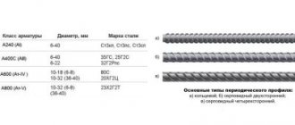
The pipe design includes various flange connections, tees, bends and other products. To seal joints in such structures, steel gaskets are used, which contain a minimal amount of carbon.
Christmas tree fittings are designed to solve many problems. In particular, one of these tasks is the installation of piping of pipelines for various purposes. The use of this equipment allows you to control the movement of the working environment and ensure the execution of processes that control production. The devices are used to seal branches from main pipelines.
Purpose of fountain fittings
Devices of this class are responsible for solving the following engineering and technical problems:
- ensuring well sealing;
- diversion of products transported through the pipeline system;
- to adjust and maintain well flow;
- when providing access to the well bottom;
- to ensure sampling without stopping production processes.
Products of this class are used at high pressures arising under the influence of loads. Fittings are used when there is a possibility of exposure to aggressive environments inside the well. Quite often it is used if the liquid contains a large number of impurities of different origins and sizes.
When using such a system, it is necessary to take into account that this equipment must have a long service life and the necessary margin of safety. The main consumers of these products are enterprises engaged in the production and transportation of hydrocarbons, as well as the construction of pipeline transport systems.
Wellhead fittings: types and design
Wellhead fittings are a part that is used during oil production in order to piping an oil pipeline, as well as sealing this section. In other words, we can say that the presence of these devices is mandatory.
Usage
Wellhead fittings are used not only for working with an oil pipeline. It can also be successfully used to conduct deep research, for example. Another option for using it is to adjust the fluid intake. All these examples quite clearly show that the use of wellhead equipment is an integral part of oil production.
It is important to add that the selection of such devices is carried out according to special criteria, and all of them are distinguished by the fact that the quality of their production is very high, as is their productivity. For example, the operating temperature range at which wellhead equipment is able to perfectly perform its functions is in the region from -60 to +40 degrees Celsius. In other words, they can be used in almost any climate.
Basic parameters of the device
The main defining characteristic for wellhead fittings was size. The average length of such a device is about three meters. As for the width, it naturally varies depending on the model, but the approximate average is 715 millimeters. The last indicator in terms of dimensions is the height, which is on average 1.5 meters.
Another important indicator for this equipment is the passage of the locking device. The numerical value of this parameter can reach up to 50 millimeters. Along with wellhead fittings, equipment such as pumping and compressor equipment is also used for the well. The pipe diameter of such devices can reach up to 75 mm. It is worth noting that this type of fitting is not a specific device, but a set of several important components that perform purposes such as sealing the wellhead. In addition, the fittings will be responsible for distributing the flow of substances that will come from the well. You can also regulate such a volatile substance as gas, for example.
Design
When it comes to the design of this device, there are several main components. These include, for example, a pipe-type head, a column-type head and a head of the valve itself. The valve head is of the adjustable-shut-off type. Even such small devices as valves, gate valves and some other small parts of this kind can be distinguished as components.
The main purpose of wellhead fittings is to contain a strong flow of pressure, as well as the ability to study this pressure inside the structure itself. To operate this type of valve, a mechanical drive is usually used. However, it happens that the pressure is too high. In this case, it will be restrained either using pneumatic type installations or using a hydraulic system. It is also worth saying that there may be wellhead injection valves. In this case, it is capable of performing the functions of injection or release of gas flows.
Features of the device
It is worth highlighting one very important advantage of this type of fittings. If any element fails during operation, it can be replaced without taking the entire station out of service. This is one of the most important criteria, since in this case it becomes possible to carry out repair work without disrupting the time interval of the station’s operation. This is one of the main requirements in the oil production environment. In addition, this helps to save a significant amount of material resources that would have been lost while the station was idle for repairs.
The structure itself is tied together using a variety of clamps and different flanges. It is also worth highlighting here that if in the entire structure any element has a deviation from the nominal data, then all other devices belonging to the locking type and all other mechanical elements will be disabled. An automatic system is responsible for this, which is equipped with any fittings of this type.
Devices for injection wells
The main purpose of this type of fittings is to seal injection wells. A special feature is that all work can be carried out while water is being pumped into the well. The main parts of the equipment include the pipe head and the tree.
The first element is used to seal the annulus. It is also necessary to perform certain repair work, research work, and some technological operations.
This element consists of components such as latches, a cross and several elements for quick connection.
Types of fittings
GOST, which are in force in our country, define the following types of Christmas tree fittings:
- Tee (cross) - the scheme allows you to connect taps to prefabricated and metering installations using flow lines.
- Double-row (single-row) - it is equipped with valves or taps. The former are used to work in oil wells, the latter - in gas wells.
In addition to the classification described above, the following is also used:
- By pressure. Typical equipment operates at pressures from 7 to 105 MPa. Valves that are designed to operate at high pressure are used for working in deep wells. In addition, it is installed in wells in which the presence of dangerous formation pressure has been noted.
- According to the size of the barrel passage. This size ranges from 50 to 150 mm. Devices with working diameters from 100 to 150 mm are installed in oil and gas wells with high flow rates.
The designer, when selecting material for the production of reinforcement, must take into account the properties of the environment. By the way, to install products in an explosive environment, it is not advisable to install components and assemblies made of cast iron.
Typical fittings include different types of gate valves, valves, etc. Special piping includes pressure reducing valves, gates and valves for supplying catalysts and operating backup fittings.
AFK transcript
AFK transcript
The only correct decoding for AFK Christmas tree equipment is given in the first, mandatory appendix of the GOST 13846 standard. This is a symbol for a Xmas tree type wellhead equipment, the peculiarity of which is the suspension of the outer tubing of the string to the sub above the cross head of the piping.
That is, the well uses two concentric-type pipelines inside the wellbore. One of them, with a smaller diameter, hangs inside the second tubing column of a larger diameter. In this case, six schemes for assembling the fountain tree are possible for various operating conditions of the well.
Symbol for fountain fittings
Appendix No. 1 of the GOST 13846 documentation provides a block diagram of the encryption of fittings and trees installed at the wellhead for their development by oil and gas producing enterprises:
- the first two letters indicate the type of product - EN and EF injection and fountain trees, AN and AF fountain fittings, which, in addition to trees, also includes piping;
- then the method of hanging the downhole pipeline is indicated, which is the tubing string - To the sub above the pipe head, without the designation of a coupling, flange or pipe holder inside the cross of this head;
- then there may be a letter indicating the production method - initially, equipment in the well is not used for gas lifts and fountains, this is not indicated in the designation, E indicates an electric centrifugal pump, Ш a rod unit;
- the number indicates the typical layout of a fountain tree - there are six options 1 - 4 tee, 5.6 cross;
- control system for taps/valves - manual method is not indicated, D means remote control, A automatic, B remote automatic;
- the nominal value of the internal diameter of the tree trunk is indicated by numbers - from 50 mm to 150 mm;
- if the size of the side pipes of the tree does not coincide with the previous value, it is indicated separately - from 50 mm to 100 mm;
- then follows the value of the working pressure - from 14 MPa to 105 MPa;
- Next comes the design of fittings for corrosion protection - K1 - K3, respectively;
- There are two types of climatic modifications for fountain fittings - HL or UHL;
- if necessary, the manufacturer indicates the modification;
- Finally, the number of the GOST standard 13846 is given.
Thus, taking into account this structure of the AFC, the decoding will look like this:
- A – a set of fittings consisting of piping and a fountain tree;
- F – fountain or gas lift method of extracting petroleum products from a well;
- K – hanging a tubing string above the pipe head with a sub.
Then the customer selects the remaining characteristics of the wellhead fittings, according to the existing design.
That is, taking into account specific operating conditions. Unlike the AF modifications, the AFK Xmas tree has an increased height due to the introduction of an additional element into the design, with the help of which the well pipeline is fastened - the tubing string. Purpose of AFK fittings
After the AFK of the reinforcement has been deciphered, it is necessary to take into account its purpose. Wellhead equipment of this type is designed to effectively solve the following problems:
- ensuring a stably sealed wellhead structure; managing mineral extraction modes;
- control of working environment parameters;
- adjustment of direction, pressure of well production;
- direction of flow through the manifold to the AGSU;
- killing a well in case of an accident;
- closing the well as planned;
- fastening one or two downhole tubing pipelines inside the wellbore;
- possibility of lowering technological equipment;
- injection of reagents into a formation or well.
AFK reinforcement is classified according to GOST 13846 according to several criteria:
- working pressure – 14 – 140 MPa;
- bore section through passage – 50 – 150 mm;
- number of tubing columns – single-row, double-row;
- type of locking devices - tap, valve;
- Christmas tree design – cross, tee, V-shaped.
Therefore, the scope of application of AFK-type Christmas tree equipment is very diverse:
- wells developed by the fountain method;
- wells with gas lift production method;
- onshore and offshore wells;
- mining of minerals under high reservoir pressure;
- development of fields with a high content of carbon dioxide, hydrogen sulfide, and sand in oil;
- wells with rod and electric submersible pumps.
In the latter case, the letter Ш or E is added to the designation, respectively – AFKSH or AFKE.
Piping design features
Two types of piping can be used in the AFK wellhead assembly. This information is not fully displayed in the symbol:
- the letter K is added when attaching the stem pipeline to the transfer flange;
- fixation of the tubing string inside the pipe head is not displayed in the symbol.
Thus, the AFK Xmas tree has a transfer flange on top of the pipe head, on which the tubing string is suspended. For this, threads such as Jee Bear, VAM Top, TMK UP PF and TMK UPP FMT, NK and NMK can be used in accordance with GOST 633, which corresponds to conical threads 1/4”, ½”, 3/8”.
Modifications of this option are hangers with a cable entry, a control channel, for coaxial (concentric) fastening of two tubing columns.
Two seals are used here, soft and metal. In aggressive environments, steel rings are used; secondary seals have the form of petal or U-shaped cuffs.
Body parts, flanges and covers are manufactured by casting and forging.
Fountain Christmas tree diagrams
The GOST 13846 standard regulates the use of six fountain tree schemes when assembling AFK. In the decoding of the symbol, this is the number immediately after the indicated letters of the product.
The same standard recommends equipping the fittings with additional elements at the customer’s request. The main differences between fountain trees are:
- number of central locking devices – 1 or 2;
- main fitting design – tee with 3 nozzles or cross with 4 nozzles;
- the number of main fittings is 1 or 2 in tee circuits, only 1 in cross circuits.
The standard does not reflect the V-shaped diagram of the fountain fittings, which was developed much later than the entry into force of this regulatory document. This is a type of AFK cross fitting, but instead of a straight cross, a beveled fitting is used. Its side pipes extend from the body, not horizontally, but obliquely upward.
Thanks to the original geometric shape, its walls are much less worn down by the pressure of oil products with a high sand content.
The main elements of the Christmas tree are:
- a cross or tee to direct the flow into the flow line, creating a spare flow line;
- pressure gauge for measuring pressure at the wellhead (mounted in the upper blind flange) and in the manifold (installed on the flow line);
- shut-off valves - installed on all sides of the tee, cross, gate valves, plug valves, ball valves with manual, hydraulic, electric drive are usually used;
- control valves - adjustable needle, cage type throttle, non-adjustable angular type fitting.
In a non-adjustable throttle, you can change bushings made of carbide material with different diameters of the internal hole. This ensures stepwise adjustment of the well modes.
The delivery set may include consumables, tools and accessories for their replacement. For example, BPV valve with lifter, plug, protective sleeve and universal puller.
Technical requirements
The main technical and operational characteristics of AFK fittings are:
- nominal diameter – 50 – 150 mm;
- nominal pressure – 14 – 105 MPa;
- body group materials – class AA – FF according to API regulation 6A;
- specification level – UTT1 – UTT3 according to GOST R 51365;
- level of requirements – UTR1 – UTR2 according to GOST R 51365;
- tubing thread – ¼ – 3/8 inch type NK, NKM according to GOST 633.
Depending on the design, manufacturer of valves, fittings, and tree layout, AFK fountain fittings may have different dimensions.
Thus, the AFK Christmas tree is suitable for flowing, gas-lift, pumping wells with sucker rod pumps and ESPs with high reservoir pressure, hydrogen sulfide, sand and carbon dioxide content.
Xmas tree design
GOST 13846–84, implies the use of tee and cross type circuits. Typical fountain fittings include the following components:
- pipe head;
- fountain tree;
- manually controlled locking devices;
- chokes.
The pipe head is designed to hang tubing in several rows on it and ensure their tightness. In addition, it takes part in some technological processes associated with the development, operation and maintenance of the well.
This device, if necessary, replaces the side valves installed on it. For this purpose, blind plugs are used, installed in threads cut in the body.
The fountain tree is designed to solve the following problems:
- sending finished products to the line;
- taking part in the installation of additional devices;
- performing measurements of pipeline network operating parameters;
- ensuring the lowering of devices for cleaning well pipes.
Locking devices are represented by plug valves and gate valves with supplied lubricant. Their main task is to block the movement of the working environment.
Technical requirements for design
GOST 13846–89 determined that Christmas tree equipment is designed to seal wells, block the movement of the working medium and perform other technological procedures. In accordance with the standards regulated in GOST 15150–69, these devices can operate at temperatures from -60 to +40 degrees.
GOST 51365–2009 defines the technical conditions and requirements for the specified fittings. Designers involved in the design of equipment should be guided by the requirements of this document.
Structure
The structure of the Xmas tree is determined by the requirements of technical specifications and drawings issued at the plant.
Reference in drawings of parts and assembly units to the manufacturer's specifications is required. If the drawings of parts and assembly units contain references to specifications, technical requirements for hydrostatic tests, tests for the influence of static mechanical loads, methods for conducting them, holding time and tolerances for holding time, tolerances for test pressures, tolerances for loading forces, it is allowed not to indicate. Design documentation is developed in accordance with the requirements of ESKD, state standards, state standards of the Russian Federation, API 6A and other regulatory and technical documentation, which are referenced in the technical specifications or agreement (contract) for the supply of equipment.
In the drawings of parts and assemblies that are subject to the requirements of Section 7 of API 6A, the following are indicated directly from the tables:
- PSL;
— mechanical properties, chemical composition of the material (if necessary);
— requirements for marking and branding.
The equipment is durable at test pressure and sealed against the environment, as well as between the cavities of tied casing strings and well pipelines at operating pressure. The magnitude of the indicated pressures corresponds to GOST 13846-89 and API 6A recommendations. The connecting dimensions of the flanges correspond to API 6A or GOST 28919-91. The equipment refers to products for a specific purpose, long-term continuous use, restored after failure, aging and repaired in an impersonal way. The equipment is serviced periodically by one operator and monitored before use. Average service life is at least 15 years. Mean time between failures, hour (cycles) is 8700 (210).
The average time between failures of equipment is determined by the average time between failures of shut-off and control valves based on the results of both bench and operational tests. Equipment failure is considered to be:
- loss of tightness in locking devices; - under-throttlement of the flow of the working medium by the needle of the angular fitting when operating the handle;
— loss of tightness of detachable connections, which cannot be eliminated by tightening;
— failure of equipment components, which requires their replacement or major repairs.
Marking of fittings
To mark this type of product, alphanumeric abbreviations are used, which are designated as follows: AFKh or AFKH, where AF indicates the type of fittings, in this case the fittings are fountain, the letter “K” indicates the method of hanging the pipeline. The letter X (from 1 to 6) indicates the diagram in accordance with GOST 13846–84. In addition, the product labeling may indicate numerical parameters showing the working diameter and pressure, climatic version and some others, in particular, the corrosion resistance class.
Installation and dismantling of fountain fittings
During the operation of an oil or gas well, the structure is installed. Column heads are used for connection. The holes located in the upper flange allow you to fix parts of different sizes. The equipment installation process is carried out in several steps.
A gasket made of low-carbon steel and having an oval shape is placed in the space between the flanges. Using an elevator, the pipe string is lowered to the installation site. After this, the pipes are assembled together using threaded connections. By the way, it makes sense to coat the threads with a protective lubricant before assembly. After completing assembly of the installation, it is necessary to carry out pressure testing.
Repair of this equipment must be performed only at special enterprises. Before sending it for repair, the unit must be disassembled. The tree must be washed and at this time the remaining components must be examined.
The Christmas tree fittings and their piping scheme are designed so that they can protect the environment from the influence of the working medium supplied in the pipeline system.