Technical characteristics of the machine 165
Technical characteristics of the machine 165 are the main indicator of the suitability of the machine for performing certain jobs on the machine. For screw-cutting lathes, the main characteristics are:
- The largest diameter of the workpiece
- Distance between centers
- Maximum length of the processed product
- Spindle revolutions per minute
Below is a table with the technical characteristics of the screw-cutting lathe 165. More detailed technical characteristics of the machine can be found in the passport of the machine 165 located below.
Attention! The technical specifications given in the above table are for reference only.
Machines produced by different manufacturers and in different years may have characteristics that differ from those given in the table.
Technical Specifications of Universal Heavy Duty Lathe 165
| Parameter | Meaning |
| The largest diameter of the installed workpiece, mm: | |
| above the bed | 1000 |
| above the caliper | 650 |
| The largest diameter of the workpiece being processed, mm: | |
| above the bed | 1000 |
| above the caliper | 650 |
| Maximum length of workpiece processed, mm | 3000 / 5000 |
| Maximum weight of the installed workpiece, kg | 8000 |
| Height of the cutter installed in the tool holder, mm | 50 |
| Headstock spindle end size according to DIN | 2-15M |
| Internal cone in the spindle headstock (metric) | 140 |
| Number of spindle speed steps | 24 |
| Diameter of cylindrical hole in spindle, mm | 128 |
| Spindle speed limits, revolutions/minute | 5-500 |
| Limits of working feeds, mm/revolution: | |
| longitudinal | 0,06-2,42 |
| transverse | 0,022-0,88 |
| cutting sled | 0,022-0,88 |
| Limits of thread pitches: | |
| metric, mm | 1-96 |
| inch, threads/inch | 24-0,25 |
| modular, module | 0,5-24 |
| pitch, diametric pitch | 96-1 |
| Accelerated movement of the caliper, mm/minute: | |
| longitudinal | 3000 |
| cross and cutter slide | 1000 |
| Maximum cutting force, kN | 41 |
| Maximum torque on the spindle, kNm | 9,5 |
| Main drive power, kW | 22 |
| Overall dimensions, mm: | |
| length | 8180 |
| width | 2200 |
| height | 1770 |
| Weight of machine model 165, kg | 15750 |
Payment, delivery of machine 165 and warranty obligations
The sale of the machine model 165 is carried out by our company with 100% prepayment if the equipment is in stock and 50% prepayment when putting the machine into production and payment of the remaining 50% after notification of its readiness for shipment. A different percentage ratio and a different payment procedure may be agreed upon with a specialist from the sales department of our company and specified in the Supply Agreement. Delivery of goods weighing less than 1 ton is carried out by transport companies, LLC PEK, Baikal-Service, LLC Zheldorekspeditsiya, etc. Delivery of goods weighing more than 1 ton is carried out by the Buyer's or Supplier's motor transport, as well as by railway transport. Transport costs for the delivery of goods are paid by the Buyer, unless otherwise agreed and specified in the Delivery Agreement. The warranty for the screw-cutting lathe 165 after a major overhaul is 6 months, new analogues of the machine 165 are 12 months. The manufacturer reserves the right to change the standard configuration and place of production of the equipment without notice!
Please note that the prices on our website are not a public offer, and please check the cost of the equipment with our sales department specialists!
If you need to buy a Universal heavy lathe 165, call:
in Moscow in St. Petersburg in Minsk +375 (17) 246-40-09 in Ekaterinburg in Novosibirsk in Chelyabinsk in Tyumen +7 (3452) 514-886
in Nizhny Novgorod in Samara in Perm in Rostov-on-Don in Voronezh in Krasnoyarsk
in Nur-Sultan;
in Abakan, Almetyevsk, Arkhangelsk, Astrakhan, Barnaul, Belgorod, Blagoveshchensk, Bryansk, Vladivostok, Vladimir, Volgograd, Vologda, Ivanovo, Izhevsk, Irkutsk, Yoshkar-Ola, Kazan, Kaluga, Kemerovo, Kirov, Krasnodar, Krasnoyarsk, Kurgan, Kursk , Kyzyl, Lipetsk, Magadan, Magnitogorsk, Maikop, Murmansk, Naberezhnye Chelny, Nizhnekamsk, Veliky Novgorod, Novokuznetsk, Novorossiysk, Novy Urengoy, Norilsk, Omsk, Orel, Orenburg, Penza, Perm, Petrozavodsk, Pskov, Ryazan, Saransk, Saratov, Sevastopol, Simferopol, Smolensk, Syktyvkar, Tambov, Tver, Tomsk, Tula, Ulan-Ude, Ulyanovsk, Ufa, Khabarovsk, Cheboksary, Chita, Elista, Yakutsk, Yaroslavl and other cities
Toll-free number throughout Russia.
In the CIS countries - Belarus, Kazakhstan, Turkmenistan, Uzbekistan, Ukraine, Tajikistan, Moldova, Azerbaijan, Kyrgyzstan, Armenia in the cities of Nur-Sultan, Bishkek, Baku, Yerevan, Minsk, Ashgabat, Chisinau, Dushanbe, Tashkent, Kiev and others for purchase equipment such as Universal heavy lathe 165, call any convenient number listed on our website, or leave your contacts under the ORDER A CALL button at the top of the site - we will call you back.
Machine passport 165
This operating manual ( Machine Passport 165 ) contains information necessary both for the maintenance personnel of this machine and for the employee directly involved in working on this machine. This manual is an electronic version in PDF format of the original paper version.
CONTENT
Purpose and scope of the machine
Unpacking and Transport
Machine foundation, installation, installation
Technical data sheet of the machine
- Basic data
- Caliper
- Tailstock
- Additional data
- Drive unit
- Friction couplings
- Specification of the main groups of the machine
- Control Specification
- Specification of gears, worms, worms, screws and nuts
- Main movement mechanism
- Feed mechanism
- Replaceable gears
- Feed mechanism
- Pumps
- Changes to the machine
- Major repairs
- Specification of accessories and accessories
Brief description of the rate
- bed
- Headstock
- Tailstock
- Caliper and carriage
- Apron
- Gearbox
- Guitar
- Cartridge
- Lunettes
- Cooling
Electrical equipment of the machine
- General information
- Description of the electric drive and control circuit
- Turning on and off the electrical equipment of the machine
- main drive
- Feed drive
- Cooling drive
- Maintenance of machine electrical equipment
- Possible malfunctions of the electrical equipment of the machine and measures to eliminate them
- Electrical Specification
Machine lubrication
- Specification for the machine lubrication scheme
- Maintenance instructions and brief description of the machine's lubrication system
Preparing the machine for initial start-up
Safety precautions
- Technical safety features provided in the machine design
- Safety rules for operating the machine
Machine adjustment
- Adjusting the spindle bearings
- Adjusting the apron safety clutch
- Adjusting the clearance in the guide of the upper and lower halves of the lead screw nut
- Layout of electromagnetic coupling fittings and adjustment
- Adjusting the tension of the main engine belts
Specification of rolling bearings and the most important plain bearings
Specification of wearing parts
- Symbols printed on machine tables
- Acceptance certificate for universal screw-cutting lathe
download the passport of the screw-cutting lathe 165 in good quality using the links below.
Machine passport 165. Option 1. Download for free. Machine passport 165. Option 2. Download for free.
Adjusting the screw-cutting lathe 165
Adjusting the spindle bearings of a screw-cutting lathe 165
After some time, it may be necessary to adjust the mechanisms to ensure normal clearances and compensate for wear. Below are instructions for regulating individual mechanisms.
Spindle supports for screw-cutting lathe 165
The spindle of lathe 165 is mounted on 5 bearings:
- 16. Front bearing 4-3182140 - double-row radial roller bearing, with short cylindrical rollers, with a flat outer ring, with a tapered bore (1:12), accuracy class 4 (C)
- 15. Bearing 5-8144 - thrust ball bearing, designed for operation under axial load in units with low rotation speeds (2 pcs), accuracy class 5(A)
- 7. Bearing 12736 - radial roller bearing with short cylindrical rollers with a single-flanged outer ring and a double-flanged inner ring, accuracy class 0(N)
- 8. Rear bearing 5-3182132 - double-row radial roller bearing, with short cylindrical rollers, with a flat outer ring, with a tapered bore (1:12), accuracy class 5(A)
Spindle Bearing Adjustment
The bearings of the front spindle support must be adjusted in the following order (Fig. 21):
- Remove the cartridge
- Remove screws 1 and 2
- Unscrew screw 3 and remove cracker 4
- Loosen nut 5
- Use nut 6 to pull off the inner race of the bearing for easier removal of the half rings 7
- Unscrew the nut 6 from the half rings 7 and remove them from the groove
- Determine the radial clearance in the bearing using an indicator. Place the indicator leg at the top point of the spindle flange and apply a load of 450 kg to the bottom point of the spindle flange. By tightening nut 5, bring the radial clearance to 0.015 mm. Using measuring tiles or lead spacers, measure the width of the groove for the half rings 7. Grind the half rings 7 to the size of the groove and install them.
- Using nut 5, tighten the inner ring of the bearing and clamp the half rings 7
- Screw the nut 6 onto the half rings 7 to prevent them from falling out and tighten it with locking screws 2 and 1
- Use nut 8 to adjust the axial clearance of the ball thrust bearings
- Insert the block 4 into the groove of nut 5 and tighten it with screw 3. The diametrical clearance of the rear spindle bearing is adjusted by nut 9 located on the outside of the headstock.
To do this, first remove the glass covering the end of the spindle, then loosen the locking screw 10 and tighten the nut 9.
After adjusting the bearing, screw 10 is locked again. The correctness of the adjustment can be established by checking the radial and axial runout of the spindle in accordance with the accuracy standards for the machine. When the gearing of the gears is turned off, the spindle should be free to turn by hand after adjusting the bearings.
Installing the headstock spindle axis
During transportation or during operation, the parallelism of the spindle axis relative to the bed guides may be disrupted. In this case, all the screws connecting the gearbox to the frame are loosened. The spindle axis is adjusted using screws 1, screwed into blocks 2, located under the gearbox on both sides and rigidly connected to the latter. After adjusting the spindle axis, the screws are tightened.
Transverse movement of the tailstock housing
Transverse movement of the tailstock body when turning cones or when installing the quill axis coaxially with the spindle axis is carried out by loosening and tightening two screws 1 located on both sides of the tailstock. When installing the tailstock into its original position, it is necessary to combine the marks marked on the plates of the tailstock body and the bridge from the rear end.
The gap in the guides of the cutting slide is adjusted by tightening the wedge 1 with screw 3, after which the position is fixed with screw 2.
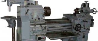
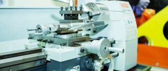
Screw-cutting lathe DIP-500 (1M65)
The DIP-500 screw-cutting lathe began to be produced instead of the 165th line lathe. With its help, it became possible to process large-sized workpieces in small-scale and individual production. Due to its high reliability and quality of manufacture, the machine was exported.
Today, these models are not produced, but you can choose their modern analogues.
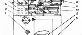
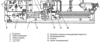
Arrangement of components of a screw-cutting lathe 165
Location of the main components of the lathe 165
Specification of components of a screw-cutting lathe 165
- Bed 1A64.01 - For RMC-2800; (165.21 For RMC-5000)
- Front headstock - 165.02
- Rear headstock - 165.03
- Caliper - 165.041
- Carriage - 165.05
- Apron - 1A64.06
- Feed box - 1A64.07
- Replaceable gears - 165.08
- Cartridge - 165.09
- Mobile rest 165.10
- Cooling - 1A64.14
- Fencing - 1A64.16
- Chuck guard - 165.19
- Fixed rest - 165.20
- Electrical equipment - 165.80
- Electrical piping: - 1A64.81 for RMC-2800 (165.81 for RMC-5000)
Model designation
In the marking of the screw-cutting lathe DIP-500: DIP means the above slogan, and 500 is the value of the height of the centers above the bed - 500 millimeters.
Download the passport of the lathe 1M65 (DIP-500)
In the marking of ENIMS (Experimental Research Institute of Metal-Cutting Machine Tools), model 1M65 stands for:
1 is the designation of the group number of lathes;
M is a designation for the modernization of the base model;
6 is the designation of the machine type;
5 is a designation of the main characteristic of the machine model - the height of the centers above the bed is 500 millimeters.
Specifications
The equipment has the following technical characteristics:
- Total weight up to 12,800 kilograms.
- Overall dimensions: 6140 by 2200 by 1770 millimeters.
- At the centers, the maximum size for processed parts is 8000 kilograms.
- 22 kW electric motor.
- The movement of the caliper with acceleration in the transverse direction is 1 meter per minute.
- In the case of moving along, the indicator is 3 meters.
- The frequency limits for the spindle are 5-500 rpm.
- There are a total of 24 spindle speed levels.
- The diameter is 128 mm at the cylinder-shaped hole inside the spindle.
- According to DIN, the headstock spindle end size is 2-15.
- The distance from one center to another is 3 thousand to 10 thousand millimeters.
- The machining diameter above the calipers is 650 mm.
- The largest processing diameter above the bed is 1000 mm.
Description
The DIP-500 machine is a turning equipment that is universal; it can be used in various fields of industry for turning operations for manufacturing products. With its help, it is possible to perform the above work with normal accuracy (H) and high productivity. Over the entire period of operation, the machine has proven itself to be highly reliable due to the quality of manufacture and ease of maintenance, and also did not require high attention or special conditions during operation.
Description and purpose
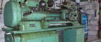
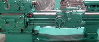
The RS3 machine tool plant, Ryazan, was initially involved in the development and production of model 165. The beginning of industrial production dates back to 1953. Later, other enterprises in the country began producing the unit. The 165 screw-cutting lathe in its basic modification offered the ability to work with medium-weight parts, with a turning diameter of up to 1000 mm.
165 universal screw-cutting lathe is designed to perform basic operations. On it you can:
- process cylindrical workpieces, conical-shaped parts, work along a complex curved, shaped profile of a rotating surface;
- carry out operations both on the external surface of the workpiece and on the internal one;
- process workpieces of both large and medium dimensions;
- make cutting of modular type threads, metric, pitch, inch;
- work with high cutting speed indicators;
- use high-speed steel tools;
- process workpieces of a wide range of metals;
- use combined cutters with inserts made of hard alloys.
Model 165 provides high precision machining. This is achieved, not least, by the design characteristics. High rigidity, parametric parameters of the spindle, drive and carriage allow turning and other processing at high cutting speeds and a wide range of tools without reducing accuracy.
Modular threads, as well as other types, can be cut either mechanically, with a cutter, varying the feed rate and pitch, or manually, using a wide range of taps, dies, and other devices. The latter are installed on a quill that has a standard type of cone for installing clamping devices.
Design of sectional horizontal pump CNS 60-165
The main structural units of the pump are the casing and the rotor.
The housing includes suction and discharge line covers, guide vanes, front and rear brackets. The housings of the guide vanes, suction and discharge covers are tightened with coupling bolts.
The guide vane, ring (with sealing rings) and impeller form the pump section. The joints of the guide vane housings are sealed with rubber rings made of oil- and petrol-resistant rubber.
Due to the fact that the pump body consists of separate sections, it is possible, without changing the flow, to change the pressure by installing the required number of impellers and guide vanes with housings. In this case, only the length of the shaft and tie rods changes.
The pump rotor consists of a shaft on which impellers, a ring, a shaft jacket, a spacer sleeve, adjusting rings and a relief disk are installed. All parts on the shaft are tightened with a rotor nut.
The rotor is supported by two radial spherical bearings installed in the front and rear brackets in a sliding fit, allowing the rotor to move in the axial direction by the amount of the rotor “run-up”.
The bearing chambers are sealed with cuffs installed in the bearing caps.
The bracket is closed from the outside with a cover in which a rotor displacement control device is mounted.
Design Features
Any machine includes some standard components. They determine what functionality a particular type of equipment has.
bed
The bed acts as a load-bearing element. The remaining parts are attached to this part. Structurally, this part looks like two walls that connect to each other. Rigidity to a certain extent is given to it by the transverse elements that organize the connection. The machine is equipped with separate parts that move along the bed.
To solve this issue, special guides are provided.
- Three of the guides have a prism-shaped cross-section.
- One part is flat.
Headstock
The headstock is needed to simultaneously perform two functions:
- The workpiece is fully supported while processing is in progress.
- So that the part rotates in a certain way.
The front part of this equipment also contains handles responsible for controlling speeds. Thanks to this, the spindle can rotate at a certain frequency.
A special diagram is usually placed next to the handle. It is enough to study it once to understand when and what part is turned on.
The headstock in front houses a high-speed box, complemented by a rotating spindle assembly. Inside this part of the structure, special bearings can be used for rolling or sliding. The chuck of the device is fixed at the end of the spindle; a connection with threads is necessarily used in the process. This unit ensures that the part rotates in a certain way while processing is in progress.
To move the carriage on the machine, bed guides with a prismatic cross-section are used. This part must maintain certain properties such as accuracy and straightness. Neglecting such conditions will not allow you to get quality work in the end.
Tailstock
The machines accommodate tailstocks, available in different versions. It is also necessary to solve several problems:
- Fix parts with significant length.
- Attach various tools such as taps, drills, reamer etc.
The headstock in front fixes an additional center in the front part. It can be rotating or stationary.
If parts need to be processed quickly, a solution with a rotating rear center is relevant. The same applies to removing chips with a significant cross-section. Such circumstances lead to the following type of tailstock design:
- Two bearings are placed in the quill hole.
- One of them is front thrust, and the second is rear radial.
- There is a bushing. Its internal part is bored to a cone.
The thrust ball bearing absorbs part of the axial loads associated with the machining process. The rear center is fixed using a tapered hole at the bushing. You can use a stopper to firmly fix the sleeve. This is relevant when it is necessary to secure other tools. Then the tool and other parts will not move, the owner forgets about the problems.
In some cases, the rear center of the headstocks remains stationary - when fastening, special plates are used, for the movement of which the guide part is responsible. A quill is installed in such a headstock, which requires a special nut when moving. Inside the quill there is a cone-shaped hole. Here is the location of two other components:
- Center of the machine.
- Shank from an axial tool.
The energy is transferred to the quill and nut when a special type of flywheel connected to the screw begins to move. Transverse movement of the quill is also permissible, which makes it possible to process parts with a flat body.
Caliper and carriage
The caliper makes it so that the tool holders move in any plane - inclined, transverse or longitudinal. Lathes allow you to communicate movement mechanically or manually. Studying the drawings of the calipers makes it clear how the tool moves along with the workpiece:
- The longitudinal type direction involves the use of the same slide. This part of the machine is also called the carriage.
- Accordingly, the transverse movement is carried out on the basis of a transverse slide. The rotating component of the structure is mounted for this purpose. Installation will not cause problems if the specified conditions are met.
The tool holder must be located above the support. Parts are developed for one place, or for several at once. The usual types of tool holders are a body with a slot, made in the shape of a cylinder. The working tool is installed in the slot. After this, fastening is carried out using a bolt.
The head with the cutter at the bottom is shaped like the letter T. Thanks to this type, the part fits into the groove without any problems. There are several options for mounting the tool holder.
Machine apron
Two couplings, fine-toothed type, are placed in the apron, due to which sets of carriages with calipers move in each of the axes. Each type of travel - along or across - is controlled by a separate handle. When turned on, the handles turn toward themselves, when turned off, away from themselves.
The apron is equipped with an additional locking device, which prevents the simultaneous activation of the feed from the roller and the lead screw. When the thread is cut from engagement with the rack, the working gear must be removed.
Gearbox
Moving the speed of the shaft with the lead screw is why a feed box is needed. The choice of specific numbers depends on the workpieces being processed and their own characteristics. The design can be described as follows:
- There is a gearbox inside.
- The gearbox itself contains several gears that switch with each other.
- The torque from the spindle is transmitted to the input shaft of the feed box through replaceable gears, which are also called a guitar.
- The usual location for the drive shaft is on the gearbox. The same goes for the screw.
- The apron transmits torque from previous parts.
Thanks to the transmission mechanism, several operating options can be allowed:
- You can manually move the cutter in relation to the workpiece.
- Regulation by feed amount.
- Reversal at the spindle and feed occur simultaneously.
- Reversing the feed while maintaining the previous position of the spindle.
- The feed is turned on and off without the user touching the spindle.
For feeds, spindle mechanisms become the main sources of movement.
Replacement gears
The headstock output shaft will not transfer motion to the transmission input shaft without replacement gears. By using different gear combinations, it is easy to make adjustments to different threads. To obtain the main result, several types of feeds are used:
Each option has its own special provisions.
The gears are secured with nuts and a washer. The number of teeth along with the module is displayed due to the end part of the replaceable parts. They can have different clearances depending on the results you want to achieve. The main thing is to regularly lubricate the gears and bushings, then they will last as long as possible. It is convenient to service any design options through the oil cap.
Ammo
During turning operations, the rotation speed of the part is very high. Therefore, cartridges must comply with special operating requirements. At the machine they are mounted on the front spindle headstock. The latter is connected to the electric motor using a gearbox and transfer case.
Studying the technical parameters of cartridges is mandatory in order to make the right choice for each specific case. In many ways, the parameters themselves are determined by the lathe and the operations that are currently being carried out.
When selecting, you should pay attention to the following indicators:
- Rotational frequency limits for chucks.
- Body hole diameter. Rods are installed in it.
- Characteristics of the product being processed. The method of fixation - with direct or reverse cams - determines the maximum and minimum size range. It is necessary to take into account what the mass of the workpiece may be.
- Diameters to do the job. This applies to the external indicator, for the connecting belt, location, size of holes for fasteners.
- Design. It determines how the workpiece will be fixed, how many clamping elements are used, how the parts are arranged, and whether several can be installed at once.
Cartridges are complex technological structures.
Lunettes
A lunette is an additional device for machine tools. This is the main or secondary support for working with workpieces. The tool adds stability and provides additional protection from damage.
Operating principle of the sectional horizontal pump CNS 60-165
The operation of the pump is based on the interaction of the rotating impeller blades and the pumped liquid.
Rotating, the impeller imparts a circular motion to the fluid located between the blades. Due to the resulting centrifugal force, the liquid from the center of the wheel moves to the external outlet, and the vacated space is again filled with liquid coming from the suction pipe under the influence of the created vacuum.
Having left the impeller of the first section, the liquid enters the channels of the guide vane and then into the second impeller with the pressure created in the first section, from where it enters the third impeller with increased pressure created in the second section, etc.
The liquid released from the last impeller flows through the guide vane into the discharge cover and from it into the discharge pipeline.
During pump operation, due to water pressure on the unequal area lateral surfaces of the impellers, an axial force arises, which tends to displace the pump rotor towards the suction side.
To balance the axial force, the pump is equipped with an unloading device, consisting of an unloading disk, an unloading ring and bushing, and a spacer bushing.
The liquid from the last stage passes through the annular gap between the unloading bushing and the spacer bushing and presses on the unloading disk with a force equal to the sum of the forces acting on the impellers, but directed towards the discharge. The pump rotor is balanced, and equal forces are established automatically.
The liquid leaving the unloading chamber cools the oil seal on the pressure side.
The suction side seal is flushed with liquid supplied under pressure from the suction line. The liquid, passing through the shaft jacket through the stuffing box, prevents air from being sucked into the pump and at the same time cools the stuffing box. Most of the liquid passes through the gap between the shaft jacket and the hydraulic seal sleeve into the suction cavity, some passes between the shaft jacket and the oil seal on the suction side, cooling it, the rest comes out through the fitting.
The tightening of the stuffing box should allow the pumped liquid to leak out between the shaft and the stuffing box packing in an amount of 5-15 l/h. A smaller number indicates that the oil seal is over-tightened, which increases friction losses and accelerates wear of the shaft jacket and rotor nut.
The pump rotor is driven by an electric motor connected to the pump through an elastic sleeve-finger coupling, consisting of two coupling halves (pump and electric motor) and fingers with rubber bushings.
The direction of rotation of the pump rotor is clockwise when viewed from the electric motor.
The pump and electric motor are installed on a common foundation plate so that there is a gap of 10 mm between the coupling halves when the pump rotor is shifted completely towards the suction side.
The unit's electric motor must be grounded before operation.
The CNS pump has self-priming capabilities. This condition is achieved by installing a valve inside the pump.
As part of the central nervous system pumping unit, as a rule, general industrial asynchronous electric motors are installed on the pump. Most often, a three-phase asynchronous motor with a squirrel-cage rotor is used for these purposes.
Pumps are manufactured with both stuffing box and mechanical seals. Leaks through mechanical seals - according to the technical documentation for mechanical seals.
The pump support brackets are made of cast iron, the material of the flow part of the pumps is TsNS SCh-20, Steel 35L, the shaft is steel 40x, the guide vane, ring and body of the guide vane, the oil seal bushing is made of press material AG-4V. The pump shaft is sealed using an stuffing box packing with a cross-section of 10 mm.
CNS pumps operate stably and for a long time with a headwater of 2-6 m. In the absence of headwater at the inlet, cavitation quickly destroys these high-speed pumps. When installing them to pump water with a temperature of more than 45°C, it is necessary to increase the pressure at the inlet to the pump.
Rice. Graphic Characteristics of pumps CNS 60-165
tested in water, density 997 kg/m3
at a rotation speed of 2950 rpm