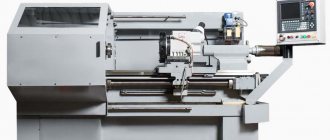
Combined machine 1M95
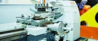
The combined machine model 1M95 is designed for work in mobile and stationary workshops. The machine consists of 2 main units: turning and milling and drilling, each with an independent drive.
Thanks to the variable height of the centers and the presence of a number of special devices: slotting, vertical and horizontal milling, sharpening, the versatility of the machine is achieved. It can be used for turning, milling, drilling, boring, slotting and cutting threads: metric, inch, modular and pitch; and also perform simple sharpening work.
Electrical equipment. Parameters of electrical circuits of a screw-cutting lathe 1M95
- Supply network: voltage - 380 V, current - three-phase, frequency - 50 Hz
- Local lighting circuit: voltage - 36 V, current - alternating
Description of the electrical circuit of the 1M95 screw-cutting lathe
Before starting work on the machine, it is necessary to connect its electrical part to the mains using the “VP-1” package switch, which turns on the machine generally.
By pressing the “START” button, the coil circuit of the magnetic starter is closed, the power contacts of which supply voltage to the starting equipment of the electric motors, and the block contact blocks the start button, which prevents further pressing of the “START” button.
The voltage from all electric motors is removed by pressing the “STOP” button.
The direction of rotation of the electric motor “1D” is selected using the drum switch “1BP”, and switching on and off is done using the “START” and “STOP” buttons.
Turning on, turning off and selecting the direction of rotation of the “2D” electric motor is carried out by the “2BP” drum switch.
The electric motor “ZD” is turned on and off by the packet switch “VP-2”. Voltage is supplied to the packet switch “VP-2” using a flexible hose through a 3-pole socket “RSh”.
The “4D” electric motor is turned on by the “VP-3” package switch.
The local lighting is switched on using a package switch “VP-4”.
General disconnection of the machine from the network is carried out by moving the handle of the batch switch “VP-1” to the “DISABLED” position.
Protection
- Protection against short circuit currents is provided by fuses
- Protection of electric motors from overloads is carried out by thermal relays
- Zero protection of the electric motor is carried out by starter coils, which, when the voltage drops to 85% of the nominal value, automatically turn off the electric motors
List of elements
The 1M95 machine is equipped with four three-phase squirrel-cage asynchronous electric motors:
- 1D electric motor for driving the turning and milling unit A02-41-4, 4.0 kW, 1450 rpm, 220/380 V
- 2D electric motor for driving the drilling unit A02-21-4, 1.1 kW, 1400 rpm, 220/380 V
- 3D electric motor of sharpening device AOL2-11-2, 0.8 kW, 2800 rpm, 220/380 V
- 4D electric motor of cooling pump PA-22, 0.125 kW, 2800 rpm, 220/380 V
- 1BP, 2BP Drum switch BP1-432 - 2 pcs. To be replaced with a new series
- KU Control buttons KU-1 - 2 pcs.
- VP-1 Input switch VP 3×25 - 1 pc. To be replaced with a new series
- VP-2 Sharpening device switch VP 3x10 - 1 pc.
- VP-3 Cooling switch VP 3×10 - 1 pc.
- VP-4 Light switch VP 3x10 - 1 pc.
- K Magnetic starter PMI-211 - 1 pc.
- K-1 Bracket for local lighting K-1 - 1 pc.
- RSh Plug socket RSh 2823 – 1 pc.
- LO Local lighting lamp 36 Volt MO-14 - 1 pc.
- TP Step-down transformer TPB-50 - 1 pc. To be replaced with TBS-2
- PR Fuse PR-60 1 pc.
- RT-1 Thermal relay TRN-10 In=8A - 1 piece
- RT-2 Thermal relay TRN-10 In=3.2A - 1 piece
- RT-3 Thermal relay TRN-10 In=2A - 1 piece
- KN-1 Terminal set KN 1010 — 1 pc.
- KN-2 Terminal set KN 1015 - 1 pc.
Technical characteristics of the machine 1M95
The technical characteristics of the machine are the main indicator of the suitability of the machine to perform certain jobs. For screw-cutting lathes, the main characteristics are:
- largest diameter D of the workpiece (part) being processed
- greatest distance between RMC centers
- maximum length of the workpiece
- spindle revolutions per minute
Below is a table with the technical characteristics of the 1M95 screw-cutting lathe. More detailed technical characteristics of the screw-cutting lathe can be found in the passport of the machine 1M95
| Quantities | ||
| Height of centers | mm | 235…355 |
| The largest diameter of the workpiece above the bed | mm | 500 |
| The largest diameter of the workpiece above the support | mm | 420 |
| Distance between centers | mm | 1000 |
| The largest diameter of the processed bar | mm | 32 |
| Spindle rotation number range | rpm | 28…125 |
| Limits of pitches of cut metric threads | mm | 1…12 |
| Limits of pitches of cut modular threads | mm | 0,25…35 |
| Limits of pitches of cut inch threads | threads/inch | 3…24 |
| Limits of pitches of cut pitch threads | pitches | 40-8 |
| Overall dimensions of the machine (LxWxH) | mm | 2750x1255x1670 |
| Machine weight (without electrical equipment) | kg | 2170 |
Attention! The technical specifications given in the above table are for reference only. Machines produced by different manufacturers and in different years may have characteristics that differ from those given in the table.
Information about the manufacturer of the screw-cutting lathe 1M95
1M95 screw-cutting lathe is the Alma-Ata Machine Tool Plant , founded in 1932 as iron foundry No. 1 of the regional department of light industry.
Since April 1942, after merging with the foundry and mechanical plant “20 Years of October”, evacuated from Lugansk, it began to be called the Alma-Ata Mechanical Plant N21 named after. 20th anniversary of the October Revolution of the People's Commissariat of Medium Engineering of the USSR.
In 1945, the Alma-Ata Machine Tool Plant named after. 20th anniversary of October.
The plant produced screw-cutting lathes: 16D20, 16D20P, 16D20PF1, TV16, 16D25, 1D95, 1E95, 1M95.
Machine tools of the plant Alma-Ata Machine Tool Plant named after. 20th anniversary of October
- 1D95
– combined screw-cutting lathe Ø 400 - 1E95
– combined screw-cutting lathe Ø 400 - 1M95
– combined screw-cutting lathe Ø 500 - 16D20
– screw-cutting lathe Ø 400 - 16D25
– screw-cutting lathe Ø 500 - 16E20
– screw-cutting lathe Ø 400 - TV-16
table lathe Ø 160
Machine passport 1M95
This operating manual “ Passport of the 1M95 machine ” contains information necessary both for the maintenance personnel of this machine and for the employee directly involved in working on this machine. This manual is an electronic version in PDF format of the original paper version. This documentation contains the Passport and Manual (instructions) for operating the 1M95 screw-cutting lathe.
CONTENT
Purpose and brief technical characteristics
Transporting the machine
Foundation and installation of the machine
Preparing the machine for initial start-up
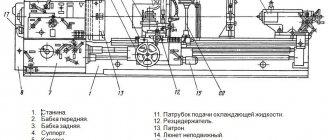
Machine passport
- Turning and milling unit
- Spindle
- Headstock
- Tailstock stand
- Support table
- Drilling unit
- Vertical milling head
- Slotting device
- Accessories and accessories
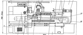
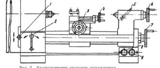
- General view of the machine with specification of controls
- Kinematic diagram
- Specification of gears, worms, screws and nuts
- Machine mechanics
- Mechanism of the main movement of the turning and milling unit
- Mechanism of the main movement of the drilling unit and vertical milling head
- Mechanism of movement of the slotting device
- Feed mechanism
- Setting up a thread cutting machine
- Bearing Specification
- Bearing layout
Description of the machine
Machine lubrication
- Lubrication scheme
- Lubrication map
Machine adjustment
Electric passport
Drawings of wearing parts
You can download the passport of the combined machine 1M95 in good quality from the link below.
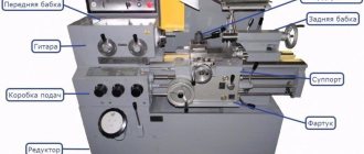
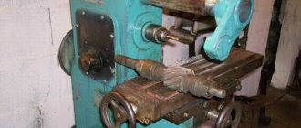
Device
The combined machine 1m95 has a classic layout with the usual arrangement of adjustment and mode settings. Certain types of additional equipment have individual installation rules. For example, according to the documentation, the sharpening device is recommended to be located separately from the main unit of equipment.
The 1m95 model bed provides high rigidity. It is made according to the classical design and has a box shape. The walls of the frame are reinforced with transverse ribs. The guides are of a prismatic type, one of them is designed to move the caliper carriage, the other moves the tailstock block. The frame is located on two base pedestals; the main drive, the electric motor itself and part of the electrical equipment for its control are mounted on the left.
The gearbox unit is capable of moving in a vertical direction. It is mounted on guides in the left area of the bed table. The rotational torque is transmitted to the gearbox via V-belts; the electric motor is located in the left base block.
The design of the gearbox ensures reliability, stable operation, fast switching, and provides familiar control mechanics using handles. It provides 6 switching stages for forward and reverse rotation, 12 speeds in total. The kinematics of torque transmission are familiar and standard, from the clutch platen and gear block to the feed chain and spindle.
The reliability and durability of the gearbox is achieved by using reliable materials. Gears are made of carbon steel that undergoes thermal hardening. In order for the structural elements to serve for a long time, you should not change the spindle speed during the working stroke.
The feed box when cutting threads can be easily adjusted using the appropriate handles. The choice of the desired type of thread can be made based on the table installed on the machine body (on the box panel).
The caliper block also has a familiar layout and design. It moves longitudinally along the bed table guides and transversely along the corresponding elements of the carriage structure. This can be done either mechanically or driven by a wheel, manually. The toolholder block has a permissible rotation angle of 45 degrees in each direction.
The mechanism is lubricated according to the instructions given in the equipment passport. The documentation indicates the types of oil, the frequency of maintenance and a description of the procedure, as well as the norms for filling technical fluid. Lubrication of individual components during operation of the machine is carried out either by natural splashing with intake from the bath (headstock), or by supply from a plunger pump (apron, guide carriages, etc.). A separate list of structural elements is lubricated only manually using an oil can.
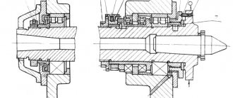
Permissible spindle play
The permissible spindle play is determined by the characteristics of the installation location and the bearings operating in the structure. The recommended fit gap according to the accuracy class is 0.005 mm. The preload of the bearings is adjusted with a nut. The change in the fit gap is regulated by a detachable adjusting ring. It is ground until the desired value is achieved, then the bearing is installed and finally tightened with a second adjusting nut. You need to start work on adjusting the gaps with the inner ring, which must be ground according to the standard caliber KP-75.
Spindle and chuck runout tolerance
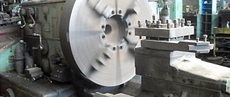
When installed on the spindle taper, the chuck can create backlash in three ways:
- lateral due to inaccurate positioning;
- lateral due to uneven pressure of the cams;
- end due to defects in flanges and spindle fit.
The tolerance of the chuck runout in combination with the structural runout of the spindle should be as small as possible. For accuracy class H, the limit is 50 microns. To achieve the required accuracy, it is necessary to bore the jaws, machine the landing cone, center and carefully adjust both the spindle and the chuck block separately.