- Home / Knowledge base / Tools, equipment, devices / Cutting tools and equipment / Counterbodies: types of counterbores and GOST 26258-87
Warehouse arrivals, promotions, sales!
Complex supplies of tools in small and large wholesale from 5,000 rubles for individuals and legal entities from St. Petersburg across Russia, to Belarus, Kazakhstan in the shortest possible time. Call or submit a request right now!
Countering is used in holes that connect to each other. The tool allows you to achieve a high level of quality and accuracy in support bases for fasteners.
Valve seat counterbore
GOST 26258–87 - the main document for cutting tools
Countering (the procedure for processing holes) is performed using four types of standard devices (essentially, drills). Countering in accordance with GOST 26258 can be classified as one of the following types:
- mounted - with a guide replaceable pin;
- with a cylindrical shank and a guide pin;
- with a pin-type locking shank and a guide (replaceable) pin;
- with tapered shank and replaceable trunnion.
Hole processing using the counterboring method
A counterbore of any of the above types, with the exception of a drill that has a cylindrical shank, is manufactured in two types depending on how its working part is implemented. There are devices with plates made of hard alloys and high-speed steel. With the help of the former, cast iron and structural steel are machined, and with the help of the latter, products from structural alloys are processed.
The diameter of the working part of a drill with a cylindrical shank varies from 2.2 to 20 mm. In this case, the cross-section of its trunnion varies from 1.1 to 14 mm. The counterbore for machining holes with a conical shank, as well as the attachment cutting tool, has a diameter from 13.5 to 61 mm and a length from 137 to 277 mm. Devices with a locking shank are characterized by a diameter from 34 to 61 mm and a length from 246 to 297 mm.
Counterbore with tapered shank
Note that the drawing of any drill with which counterbore is performed also contains its other geometric dimensions, in particular, the length and cross-section of individual elements of the tool.
GOST 26258 contains references to a number of other State Standards that describe the requirements for:
- keyway parameters (standard 9472);
- Morse cones (2848 and 25557);
- metric threads (24705);
- sizes of locking shanks (3009).
This is interesting: Metal cutters for a household drill: types and application features
Purpose of the tool
The principle of operation of the counterbore is similar to the operation of another processing tool - a countersink.
A countersink is designed to expand finished round holes by cutting with tool blades. In this case, the thickness of the removed metal layer is small.
Countering is very rarely used manually due to the low accuracy of this processing method. Depending on the nature of the work, it is installed on the following machines:
- drilling;
- milling;
- boring;
- turning
The tool is most widely used as a processing tool on drilling-type machines.
The sharp elements of the counterbore are located in the end part. They are evenly distributed around the perimeter of the main shaft, which rotates around its axis. This design caused the spread of the tool for use on drilling rigs.
Countering metal can pursue the following purposes:
- obtaining a perfectly flat reference plane located at an angle of 90° relative to the hole;
- elimination of defects in the inner surface of holes;
- chamfering an edge;
- grinding of sagging and burrs of metal;
- creating multi-stage holes.
The tool has no requirements for the material of the workpiece. It copes equally well with all types of ferrous and non-ferrous metals, as well as alloys based on them.
The accuracy of work meets modern standards used in the production of precision engineering parts up to accuracy class 2.
GOST 26258 requirements for the described tool
The drawing for the production of the cutting devices in question must be approved by the manufacturer. Tools made of high-speed steels are produced from alloys that meet the provisions of Gosstandart 19265 (working part), and steels 40X and 45 (shank) in accordance with Gosstandarts 4543 and 1050. The hardness of the shank should be in the range of 37–56 units on the Rockwell scale, working parts – 62–66 units.
Drills with carbide inserts are made from the following grades of materials:
- steel 40Х, 45Х or 45 (shank);
- alloys according to State Standard 3882 - T15K6, VK6M, VK6 and T5K10 (directly working part).
Drill with carbide inserts
A counterbore of the mounted type and with a cylindrical shank is always made in one piece if its cutting part has a cross-section of no more than 8 mm. For larger cross-sectional values, fixtures are produced welded. The solder used for welding is usually MNMts 68-4 material or L68 and L63 brass. Note that the tool drawing contains information about the thickness of the solder layer (as a rule, it is less than 0.2 mm).
Attachment type tool
On the working part of the described drilling tool, the presence of burns and chips, corrosion manifestations, cracks and cavities is excluded. In addition, the presence of rough marks on drills that have undergone a grinding operation is not allowed. The durability period of the cutting devices we are interested in varies from 3 (drills with a cross-section up to 3.8 mm) to 27 (drills from 52 to 61 mm) minutes. And the average period varies from 8 to 69 minutes. In this case, the allowed tool wear is 0.3–1.5 mm.
Area of application of the tool
Counters are a multi-edge tool and are a type of countersink. They are used when performing technological operations to create a cylindrical or conical surface. Face countersinking is used to level the support areas near the finished hole. The resulting recesses allow you to place the heads of the fasteners so that they do not protrude above the surface.
The following types of machining are carried out using the counterbore process:
- Alignment of ends in internal structural elements;
- Supporting surfaces for fasteners are made;
- Burrs and sagging are removed;
- Stepped holes are created;
- Chamfering edges.
The cutting tool allows you to work on the machine with steel, cast iron workpieces and parts made of non-ferrous metal and various alloys.
Countering holes is aimed at solving important technological problems:
- Increased quality of processing of internal elements.
- Preparation for subsequent processing and assembly operations.
- Implementation of standards for geometric accuracy and location, for example, normal location to the axis of the machined hole.
Due to the similarity of design and technology of use, the counterbore was called an end countersink.
The tool is used on drilling, turning, milling, boring and specialized metal-cutting machines.
A variety of counterbores for processing hard-to-reach areas include reverse tools. The counterbore is mounted on a mandrel and trims the end by moving the quill from bottom to top, and not vice versa, as in traditional machining on a machine.
Areas of application for counterbores
Counterbodies are used for working on cast iron, steel, and non-ferrous metals. The tool improves the quality of the processed surface and guarantees strict perpendicularity of the hole to the axis of the finished product.
Image #6: Countered end plate
The counterbore is used to create reference planes in holes for screws, washers, bolts, and rings. The tool is also necessary for cleaning the ends of embedded parts of structures.
For reverse counterbore (reaming), tools with a large number of blades (up to 14) are used. This operation allows you to make a cylindrical recess as accurate as possible.
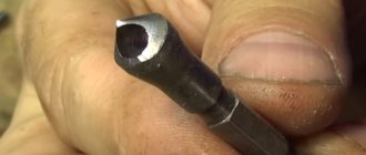
Image No. 7: Piston counterbore
Motorists use counterbores for turning pistons. Carrying out the operation yourself allows you to turn the valves using a counterbore, without resorting to turners. It is advisable to study the drawings and practice on old pistons before repairing.
What is a counterbore and why is it needed?
From a technical point of view, it is a cylindrical axial type tool, in which the cutting elements are located at the back of the end of the tool. There are usually deep grooves on the sides of the counterbore - with their help, chips are quickly removed. For reliability, the counterbore is fixed using a pin - it ensures precise perpendicular direction of the working tool, which has a beneficial effect on the processing accuracy.
The counterbore can be installed on industrial and hand drills, on lathes, and on various metal-cutting equipment. Please note that there is an element in the form of a tail located at the back - it ensures reliable fixation of the tool on the metal-cutting tool, which has a beneficial effect on cutting accuracy.
With a counterbore, all the cutting elements are located behind the axial part - therefore it is impossible to drill with such a tool. In what areas of activity then can this tool be used and what technological problems can it solve?
Application
- Processing of various standard type holes located on reference planes. These holes are for fastening elements using bolts, screws, washers, and special fixing rings.
- Final processing of the ends of various metal elements (metal forging in this case is needed to clean surfaces, eliminate minor irregularities and defects associated either with the heterogeneous structure of the metal itself, or with poor quality initial processing).
All manipulations that can be performed using counterbore are called the general term counterbore. The best way to counterbore is to level the uneven metal surface next to the hole. This treatment has a beneficial effect not only on the appearance, but also on the physical and operational properties of the part.
In most cases, metal counterbore is used for processing steel and alloys. If necessary, it can be adapted for processing any non-ferrous and precious metals - copper, aluminum, lead, silver, gold + various alloys.
Varieties
The following varieties are produced in Russia:
- With a cylindrical cast or welded tail, which is fastened together with a pin-retainer. This type of part is the most common in production, where the same tools are used for a long time, so the master does not need to fine-tune the tools.
- With a conical tail, which has a movable joint with a pin-lock. If necessary, the journal can be removed and replaced with another one, which allows increasing the processing accuracy. Such counterbores are usually used if very high machining accuracy is required. For example, when working with non-ferrous metals and ductile alloys.
- There are also attachment-type counterbores, with replaceable tails and/or trunnions. They are quite rare, since the first two types of parts almost completely cover all major applications. However, non-standard counterbores can still be found - when processing expensive metals and alloys, where minimal chip yield is required, when working with heavy-duty metals, when working with non-standard tools.
Countering a hole: basic rules
Countering a hole is an operation that is carried out on machines with a minimum stroke. The countersinking mode configured on drilling, turning, boring or other metalworking equipment is optimal for operation. In some situations, combined type tools are used, which perform several operations in one approach: drilling, countersinking, countersinking, countersinking, etc. All these processes are part of the drilling operation.
Despite the fact that cutting tools are mainly used on industrial equipment, counterbores are also purchased for home use. When working with such a tool, craftsmen should adhere to several rules.
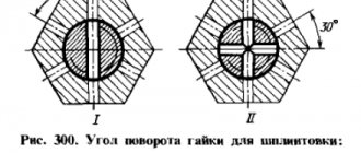
- When machining open surfaces, secure the stop to the shank using a stop nut and lock nut.
- When counterboring holes for screw and bolt heads, use a tool with a 90-degree point angle. The need to reduce the angle is justified to maintain the cut on the surface of the holes being machined.
- Make indentations in 2 stages. First, drill the hole to the desired diameter, then give it the required shape and size.
- Make sure that the entire surface of the tool guide does not come into contact with the bushing. If this rule is not followed, the metal counterbore will become stuck in the bushing due to the intense heating of the material caused by the rotation of the spindle.
This is interesting: Carbide drills for metal: types, features, selection criteria
Cylindrical counterbores for processing supporting surfaces for fasteners. Specifications
| Designation: | GOST 26258-87 |
| Status: | active |
| Type: | GOST |
| Russian name: | Cylindrical counterbores for processing supporting surfaces for fasteners. Specifications |
| English name: | Counterbores desighed for working bearing surfaces under fastenings. Specifications |
| Date of text update: | 06.04.2015 |
| Description update date: | 01.06.2019 |
| Publication date: | 05.02.1988 |
| Effective date: | 01.01.1989 |
| Last modified date: | 12.09.2018 |
| Area and conditions of application: | This standard applies to cylindrical counterbores intended for processing supporting surfaces for fasteners, except for counterbores for enlarged washers for processing supporting surfaces with a diameter of over 61 mm and protruding bearing surfaces with a diameter of up to 15 mm |
| Instead: | GOST 26258-84 |
| Is located in: | All-Russian Classifier of Standards → Mechanical Engineering → Cutting Tools → Other Cutting Tools Classifier of state standards → Machinery, equipment and tools → Industrial tools and accessories → Tools for cutting All-Russian Classification of Products → Tools, technological equipment, abrasive materials → Cutting tools → Countersinks → Cylindrical countersinks for machining support areas for fasteners / |
Description of the design and modification of the tool
The counterbore is considered an axial cutting tool. On one side of the cylindrical body there is a working area with several blades, and on the opposite side there is a shank for mounting in the machine chuck. A special feature of the tool is the location of the working processing edges in the end part. Helical grooves run along the side surface to remove chips from the processing zone.
Perpedicularity and positioning accuracy during the processing of end surfaces is ensured by a special journal in the cutting zone of the tool.
During the cutting process, the guide pin enters the hole and is tightly fixed in it, ensuring the correct, coaxial position of the tool.
Installation and fixation of the counterbore on the machine is carried out, as with all axial tools, by means of a shank.
Types of counterbores
Countersinks for metal-cutting machines are divided into two large groups: cylindrical and conical.
For conical countersinks, the working head profile angle is 60°, 75°, 90° and 120°. The number of cutting edges depends on the diameter. Counters can be with a cylindrical or conical shank. The conical tool is intended for finishing fasteners and for chamfering. The production of conical countersinks is regulated by GOST 14953-80.
Cylindrical countersinks come with a cylindrical and conical shank. An option is available with a wear-resistant coating of rubbing areas. The intended purpose of such a tool is to process support areas.
- With solid guide pin and cylindrical shank shape.
- With replaceable trunnion and conical shank.
- Mounted design, when the blade head is mounted on a mandrel. The guide pin is replaceable and is also fixed to the mandrel.
- With change of shank and axle. Installation on the machine is carried out using a pin lock.
Materials and working attachments
The working area of all mounted bores can be made solid from high-speed steel or with brazed plates made of carbide. Cutting tools with a cylindrical attachment point are made only from quick cutters.
Counterbodies with built-in carbide plates
Counterbodies, with built-in hard alloy plates, allow processing of cast iron of various grades and structural steels. Quick cutter tools only work with steels.
The number of blades on the counterbores depends on the design. A solid tool with a cylindrical end has 2-4 cutting edges. Tools in other categories only have 4 blades.
The method of securing the tool in the machine is influenced by the design of the shank. The counterbore with a cylindrical edge is installed directly into the machine chuck. The tool with a cone is mounted in a mounting hole with a special Morse taper. Installing a counterbore with a pin-type locking mechanism requires a pin lock on the machine.
Types of counterbores
We will describe what the tool looks like, what elements it consists of, and what modifications there are.
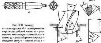
Design features (information and drawings)
Countering
- a cylindrical tool of axial type with cutting teeth located in the end part. There are grooves on the side surfaces of the product that are designed to remove metal shavings from the work area.
Image #2:
Types of counterbores
The designation of the counterbore in the drawing is given in GOST 26258-87. The same regulatory document defines the technological features of the production of cutting tools and divides them into categories. According to the classification, the following are produced:
- counterbores with cylindrical shanks and guide pins, which are integral with the tool;
tools with conical shanks and removable trunnions;
attachment-type products in the form of cutting heads (put on frames with conical shanks, the axle is replaceable);
tools with replaceable trunnions and shanks, which are mounted in pin locks of machines.
Image #3:
The working parts of the instruments are manufactured:
- entirely made of high-speed steel;
with carbide tipped.
Counterbodies for metal have a different number of working blades. Products with cylindrical shanks are equipped with two to four blades. All other varieties - four.
The type of shank affects how exactly the tool is fixed in the machine.
- Counters with cylindrical shanks are installed in chucks.
Tools with conical shanks are mounted in mounting holes, Morse tapers.
Products with shanks for fastening in pin locks are used together with machines equipped with these fittings.
Requirements for the production of counterbores according to GOST
Requirements for the manufacture of counterbores are regulated by GOST 26258-87. This document indicates that attachment-type tools, the diameters of the working parts of which are less than 8 mm with cylindrical shanks, are produced in one piece. And counterbores with cutting parts larger than 8 mm have a welded structure.
Image #4:
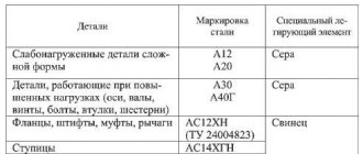
The central rods of the products, as well as the shanks, are made of steel grades 45 and 45X. There are two types of material used for cutting parts.
- High-speed steel - the requirements for it are set out in GOST 19265.
Carbide inserts VK6, VK6M, T5K10, T5K6 - the requirements for material characteristics are described in GOST 3882, for geometry and dimensions - in GOST 25400.
Image No. 5: Materials that go into the production of counterbores with carbide inserts
Carbide plates are attached to the working parts of the tools with solders of the MNMts 68-4-2 grade and L63 or L68 brass. The minimum solder thickness is 2/10 mm.
Countering in different versions and types
In accordance with GOST, countersinks are divided into several types:
- With permanent journals and cylindrical shanks.
- With variable journals and conical shank.
- Mounted, with replaceable pins.
- With replaceable trunnions and pin-lock shank.
Based on the material of manufacture, the following types are distinguished:
- a tool with a working surface made of high-speed tool steels;
- with a working surface made of carbide steel.
The main structural element of trunnion-type counterbores is the working part with blades and the shank.
The number of blades may vary, but the most common is the three-blade countersink drill.
The tool is secured in the machine chuck cam using a shank. Depending on the type of tool, the shank can be cylindrical or Morse taper.
Counters with a pin allow for better alignment of the hole being machined and the recess for fasteners. The trunnion in such instruments plays the role of a guide. The main purpose of tools with a trunnion is to counterbore the end surfaces of bosses for nuts, washers, and rings.
To remove large metal allowances, two-pronged end countersinks are used. This variety is distinguished by the presence of a small (0.3 mm) displacement relative to the tail and working parts of the tool. Each tooth is sharpened along the back at a certain angle. In this way, a front cutting part is formed with an offset along the axis and a transverse blade with a point. This design made it possible to increase processing accuracy.
GOST 26258-87 defines the important technical requirements for counterbores:
- the working part of the tool is made of tool high-speed steel, the shank is made of steel 45 (GOST 1050-74) or 40X (GOST 4543-71);
- tools with a diameter of less than 8 mm with a cylindrical shank are made in one piece, varieties with a conical shank or models with a diameter of more than 8 mm are welded;
- the cutting part should not have chips, burns, burrs or other defects;
- the reverse taper must be uniform along the entire length of the working part. For counterbores made of tool steels, this figure is 0.08-0.16 mm, for carbide steels - 0.05-0.10 mm per 100 mm of length.
What is this tool and what is its use?
A counterbore is a metal-cutting tool for working with drilled holes. Countering for holes is used to obtain supporting surfaces for washers, bolts, screws and rivets, as well as to improve the accuracy of the hole. Processing a hole using a counterbore is called counterbore.
Materials for cutting part: high speed steel (HHS) and carbide steel. All counterbore parameters, as well as the designation, must comply with GOST 26258-87.
The product itself consists of several components:
- shank (main part);
- blades (working part);
- guide pin;
Counterbodies are used for working on wood and metal.
Counterbore, GOST 26258-87:
- The counterbores with trunnions are solid.
- Mounted bores with replaceable pins.
- Mounted onto the base. The base can be an ordinary drill, but in this design it acts as a pin.
- The cutting part has a diameter of 0.022 cm to 2 cm. With a cylindrical shank.
- Cutting part with a diameter of 3.4 cm to 6.1 cm. With a base for a pin lock;
- The cutting part has a diameter from 1.35 cm to 6.1 cm. With a conical base.
Tools made from HSS steel are used to work with many grades of cast iron and various grades of structural steels. Tools with a carbide working part can be used for machining parts made of structural steel only.
Installation in the cartridge is carried out as follows:
- The cylindrical shank is inserted directly into the chuck;
- The conical shank is secured using a Morse taper;
- To secure the shank with a pin lock, it is attached to a corresponding lock.
Requirements for the product, according to GOST 26258-87:
- Cylindrical counterbore, the cutting part of which is less than 8 mm in diameter, must be made in one piece.
- Counters with a cutting part larger than 8 mm are made of several parts; welding is used to connect the parts of the tool.
- The shank is made of tool steel grades 40X, 45X or 45.
- The reverse taper must comply with the specified standards.
Requirements for the weld seam in the production of counterboring tools:
- The thickness of the solder (material MNMts 68-4 is often used) should not exceed the standards specified by GOST 26258-87.
- Such a seam should not contain any flaws (cracks, burns).
- Also, the cutting part of the tool should not contain any damage.
The designation and markings are applied to the product during manufacture. The appearance of the product is analyzed through visual inspection. Analysis of drills for compliance with specified dimensions and requirements for durability and performance is carried out using special instruments and devices in drilling machines.
Tool design
Taking apart the general design of the counterbore, it can be imagined as a rod consisting of a tail, working and connecting parts. Through the first, they are clamped in a metalworking machine. The second contains the cutting edges and the axle, and it is the one that is in direct contact with the workpiece. The third simply transmits torque from the production unit to the counterbore working area.
According to GOST 26258-87, the following types of counterbores are manufactured:
- with a cylindrical tail and a permanent guide pin;
- with a conical tail and a replaceable guide pin;
- with a tail for a pin lock and a replaceable guide pin;
- mounted counterbores with a replaceable guide pin.
The shape of the tool shank determines how it is mounted in the machine. Cylindrical ends are inserted directly into the equipment chuck, conical ends use an adapter, a Morse taper, and for tails for a pin lock, the machine must have one.
The configuration of the working part determines the processed diameter of the supporting plane, and what material such a tool can work with. Counterbodies for metal are made of high-speed steel and with carbide inserts. For the manufacture of solid face countersinks with a cylindrical tail, only high-speed steel is used. In other cases, for example in mounted ones, carbide plates can be added. They expand the capabilities of the tool, allowing you to process workpieces not only from ordinary structural steel, but also from cast iron. The inserts are fastened using a thin layer of brass solder or MNMts 68-4-2 alloy. The number of blades varies from two to four. Along the length of the rod in the working area, grooves are cut through which steel shavings are discharged. Also, along the entire length of the working part of the counterbore or the length of the carbide plates, if any, it has a reverse taper with a constant angle of inclination.
When inspecting a tool, identifying signs of corrosion, burrs and cracks anywhere, as well as chips and burns in the working area is considered a reason for rejection.
Question answer
How to determine the optimal cutting speed?
The cutting speed is selected taking into account the tool diameter and rotation speed. It is necessary to introduce correction factors. The obtained data can be used to calculate the spindle speed.
How to determine the depth of cut with a counterbore?
This indicator is calculated as half the diameter of the cutting tool minus the diameter of the rough hole.
Is it possible to make custom-made counterbores?
Yes, we will produce tools according to your drawings in a period of 5 to 45 days.
Tool material
Structural steel grades 45, 40X and 45X are used for the base counterbore rod. The cutting zone can be manufactured from the following materials:
- The monolithic cutting area is made of high-speed alloy that meets the recommendations of GOST 19265.
- The material for carbide cutting inserts is selected from alloy VK8, VK6, VK6M, T15K6, T5K10.
- The properties of the material and the requirements for it are set out in GOST 3882. Compliance with geometry and dimensional parameters is controlled by GOST 25400.
Carbide plates are attached to the holder using solder MNMts 68-4-2, brass type L63 and L68. The solder thickness must be no less than 0.2 mm.
Wood, plastic and soft metals are processed with countersinks made of tool steel. Carbide countersinks have high durability and can withstand significant cutting forces that arise when machining strong steel parts on a machine.
The hardness of the cutting surface of countersinks made of tool steel is not lower than 62..66 HRC, the hardness of the shank is 36...45 HRC. The hardness on the body along the entire length of the countersink with carbide inserts is 35…46 HRC.
Features of countersinking holes
- When processing hard alloys and cast iron, it is necessary to use cooling emulsion compositions to remove heat.
- It is very important to choose the right tool for the job. It is necessary to take into account the material of the workpiece and the nature of the work.
- When countersinking, pay special attention to the specified processing parameters - diameter, required accuracy, size of the recess.
- Pay attention to the method of fixation on the machine; if necessary, purchase the necessary additional equipment.
A countersink will make the hole precise
Countering is performed on machines with a minimum working stroke. Countering is carried out in modes similar to countersinking on drilling, turning, boring and other machines. In some cases, it is permissible to use combined tools that allow you to simultaneously perform several operations - drilling, countersinking, countersinking, countersinking, etc. All these operations are parts of the drilling process performed on special equipment.
To increase productivity, machines are used that have the ability to change types of cutting tools.
After drilling, minor defects form in the hole, which can be eliminated using a countersink, as well as by countersinking or boring. Countering is the final process in hole making. Using this operation, the hole is given the required geometric shape, and deformations and roughness that remain after drilling are eliminated from its surface.
For counterboring, end countersinks with teeth on the end are used. During counterbore, recesses are created for the heads of hardware, which subsequently ensure their reliable fixation. Depending on the type of tool used, conical and cylindrical recesses are created.
Cutting mode parameters for counterboring:
- Cutting speed. The parameter is determined based on the diameter of the metal-cutting tool and its rotation speed. When determining the required cutting speed, correction factors must be taken into account. Based on the calculated data, the spindle rotation speed is calculated.
- Innings. This value is equal to the distance in millimeters by which the cutting part of the tool will move in relation to the axis of the workpiece in one full revolution. It is calculated from tabular data, based on the material being processed, passport data and technical parameters of the machine.
- Depth of cut. The parameter is calculated as half the diameter of the cutting tool minus the diameter of the preliminary hole. For comparison, when drilling, the depth of cut is determined equal to half the diameter of the drill.
- Cutting power (effective and required). When determining the required and effective cutting power, the rationality coefficient of the selected cutting modes is calculated. The calculation of the coefficient is carried out according to the formula - required power divided by the power of the machine engine. The most rational indicators are K = 0.85–0.9. If the calculated indicators differ from rational ones, the determination of cutting conditions must be repeated.
This calculation of parameters is used to determine operating modes with counterbores in accordance with GOST 26258-87.
Despite the fact that counterbores are a type of cutting tool used on industrial equipment (drilling, turning, boring and other machines), they can also be used by home craftsmen. When using face countersinks by a home craftsman, it is necessary to adhere to the same rules, and also be sure to calculate the same parameters as in a production environment.
The difference between counterbore and other metalworking operations
Countering is a finishing operation that follows after countersinking and usually before reaming. The process eliminates minor defects from previous processing. The master removes roughness from the surface of the hole and gives it the correct geometry. When counterbore, conical and cylindrical recesses are cut out for the heads of fasteners and a smooth surface is obtained for high-quality contact of the part with them.
All operations in the cycle of creating holes in a workpiece: drilling, countersinking, boring and counterboring (countersinking) are performed on the same equipment. Drilling, milling, turning and boring machines are used for this.
The lateral surfaces of the cylindrical recesses for bolts must comply with the dimensions and quality requirements established in the drawings. The process of their processing is called reverse counterbore. It uses countersinks with a large number of cutting edges, sometimes their number reaches fourteen.
This is interesting: Heat-resistant steel - grades, types and composition of heat-resistant steels and alloys
The parameters set on the machine during processing are calculated and determined according to current industry standards and product drawings. These include: feed, depth and cutting speed, effective and required power, as well as the efficiency factor calculated for the selected operating mode.
Counterbore and counterbore: differences
The counterbore differs less from the counterbore than it seems to the uninitiated person. Namely: countersinks are called countersinks. So, if you need to align the end parts of an already formed recess, counterbore is required. For chamfering, deburring, and changing hole configurations, purchase a metal countersink.
Production requirements
The technology for producing counterbores is brought into compliance with the provisions of GOST 26258-87. According to the requirements, tools with a working area diameter not exceeding 8 mm, and a cylindrical tail part, as well as an attachment structure, are manufactured solid. Counters with an outer size of 8 mm, regardless of the type of shank, are welded. The working head and the clamping part in this case are made of different grades of steel.
Increased demands are placed on the quality of the connecting seam during welding. The presence of voids, cracks, oxides, porosity and burns is unacceptable.
Defects in the form of oxides, cracks and nicks are excluded on the edges. The sanded areas should not contain damage or tears, chips or burns.
Geometry control involves checking for reverse taper in the tool when the diameter decreases towards the tail. The counterbore must have a uniform diameter along the entire length of the cutting part of a high-speed tool. The permissible deviation is less than 0.08-0.16 mm per 100 mm of length. There should also be the same size in height of the plates on the counterbore with brazed plates, the tolerance for which is 0.05-0.1 mm per plate size.
Basic technical requirements for the manufacture of counterbores
According to GOST 26258, attachment tools, as well as tools with a working part with a diameter of up to 8 mm and a cylindrical shank, are manufactured in one piece. Counters with a working part, the diameter of which is over 8 mm, and a cylindrical shank, as well as with a locking and conical shank, are made welded. Cracks and arson should not be allowed at the welding site, and oxidation, fistulas and pores should not be allowed in the welding seam.
The body along the chipping part of the screw grooves and the shank of all counterbores are made of steel 45Х, 40Х (GOST 4543) or 45 (GOST 1050). Depending on the design of the tool, the material of its working part will be as follows:
- The 1st version of the counterbore has a cutting part and ridges of helical grooves made of high-speed steel, manufactured in accordance with GOST 19265.
- For the 2nd version - the material of the cutting part is one of the following grades of hard alloy according to GOST 3882: T15K6, T5K10, VK6M, VK6. Dimensions and shape of carbide plates according to GOST 25400.
To attach carbide plates to the working part, MNMts 68-4-2 alloy or L68 or L63 brass (GOST 15527) should be used as solder. When soldering, a layer of solder up to 0.2 mm thick should be formed.
All surfaces of the tool should be free of traces of corrosion, burrs, cracks and shells, polished surfaces should be free of rough surfaces, and the cutting part should be free of burns and chips. After heat treatment of the counterbore, its center holes should not have developed areas or nicks.
This is interesting: Copper ore - copper mining, refining, deposits
The reverse taper of the edges of the working part of the tool should be uniform: for counterbores of the 2nd design along the length of the carbide inserts, and for the 1st design - along the working part. The value of the reverse taper of a tool with a working part made of high-speed steel should not exceed the values of 0.08–0.16 mm per 100 mm of length, and those equipped with carbide inserts – 0.05–0.10 mm per plate size.
Requirements of state standards for the manufacture of counterbores
Requirements for the production of countersinks are determined by GOST 26258-87. Thus, according to this document, a tool of the attachment type, as well as one whose working part has a diameter of no more than 8 mm and whose shank has a cylindrical shape, is produced in one piece. Tools with a cutting diameter greater than 8 mm, with all types of shanks, must have a welded construction. High demands are placed on the quality of the welds used to make such a tool. In these seams, the presence of cracks and burns is excluded; they should not contain traces of oxidation, tubular cavities and pores.
The main rod of the counterbores, including the shank, is made of steel grades 45, 40 X or 45 X. The following materials can be used for the cutting part.
- Tools that are entirely made of high-speed steel are made of material, the requirements for which are specified by the provisions of GOST 19265.
- Materials for the cutting part of counterbores with carbide inserts can be VK6, VK6M, T5K10, T15K6. Requirements for the material characteristics of such plates are specified in GOST 3882, and for their geometric shape and dimensions - in GOST 25400.
Carbide plates on the working part of the tool are fixed using solder grades MNMts 68-4-2, brass grades L63 or L68. The thickness of the solder should be at least two tenths of a millimeter.
Material of counterbores with carbide inserts
Like the surface of drills, cutters and other metal-cutting tools, the surface of counterbores must be free of defects - traces of corrosion, cracks, voids and burrs. Cracks and tears are not allowed on the polished part, and chips and burns are not allowed on the working part. The center holes of the counterbores after quenching and tempering should not have recesses or developed areas.
Such a geometric parameter of counterbore as reverse taper (reducing the diameter towards the shank) must be uniform along the entire length of the working surface (for tools made of high-speed steel), along the entire height of the cutting inserts (for tools with carbide tips). Tolerances for this parameter, according to the drawing and the requirements of the regulatory document, should be no more than 0.08–0.16 mm per 100 mm of the length of the working part for counterbores made of high-speed steel, and 0.05–0 for counterbores with tipped carbide. 1 mm for the entire plate size.
GOST requirements
In Russia, the procedure for manufacturing counterbores is regulated by the state standard GOST 26258-87, as well as some auxiliary regulatory documents (GOST 1050-74, GOST 19265-73 and some others). In accordance with these documents, the following requirements must be taken into account:
- Counters with a small diameter (up to 8 mm) have reduced strength, so they require additional operating rules. For such parts, the tail and the trunnion must be made as a single element (that is, the presence of moving parts is not allowed, and even more so, such parts cannot be made collapsible). Please note that in the case of such parts, welding is also not allowed, since even the highest quality and precise welded connection does not allow obtaining a high-strength part, so a small welded bore will quickly break, which can lead to a decrease in the quality of processing. This will not benefit the holes, which can create an emergency situation.
- Counters with a diameter of more than 8 millimeters have increased strength. Therefore, their tail and trunnion must be connected by welding. Special ultra-precision welding is used to connect individual elements to each other.
- The manufacture of counterbores with movable joints without welding is permitted, but it is associated with limitations. Therefore, in practice they are quite rare.
All parts, according to GOST, must have a uniform, smooth surface without cracks or irregularities. If defects are detected, the part is considered defective and withdrawn from circulation.
Types and design features
A counterbore is a cylindrical tool of an axial type, the cutting teeth of which are located on its end part. There are grooves on the side surface that serve to remove chips from the cutting area. A special trunnion, which is also located on the end part, is responsible for ensuring the perpendicularity of the plane being processed and the axis of the hole. Such a guide pin is fixed in the hole of the workpiece during processing. Like any other axial type tool (drills, etc.), this device is fixed in the machine using a special shank.
The working part of the counterbore with a permanent guide pin
- with a cylindrical shank and a guide pin, which forms a single whole with the counterbore;
- with a conical shank and a trunnion, which can be removed and replaced with another;
- attachment type in the form of a cylindrical cutting head, which is put on a special mandrel with a conical shank (the guide pin is also replaceable and fixed in the same mandrel);
- with a replaceable pin and shank, which is fixed in the pin lock of the equipment.
Types of counterbores (click to enlarge)
The working part of attachment-type counterbores, devices with conical-type shanks and secured in a pin lock, can be produced in two designs:
- entirely made of high-speed steel;
- with hard alloy tips.
GOST 26258-87 establishes that tools with a cylindrical shank are made only from high-speed steel. If we talk about the purpose of tools with a cutting part made of different materials, then those equipped with carbide inserts can be used to work with both cast iron and structural steels, and counterbores with a working surface made of high-speed steel are used exclusively for processing parts made of structural steels.
Reverse counterbore
The number of working blades for different types of counterbores is also different. Thus, the working part of tools with a cylindrical shank can be equipped with two or four blades, for all other categories - only four.
The type of shank the tool is equipped with determines how it is installed on the equipment.
- A counterbore with a cylindrical type shank is installed in the equipment chuck itself.
- To install a tool whose shank has a conical shape, a mounting hole made under a Morse taper is used.
- To install a counterbore fixed in a pin-type lock on the equipment, the machine must have such a lock.
Some of the varieties of bores
Design features
The counterbore is an axial-type metalworking device. It includes three components:
- Working part. At the end of the tool there is a contact area with cutting blades for processing the metal surface. It also includes a guide pin.
- Tail part. It is located on the opposite side and is fixed in the machine chuck.
- Connecting part. Located between the above elements. Its purpose is to transmit torque from the machine to the cutting edges.
The counterbore can be a monolithic device or a prefabricated structure, depending on the type of execution.
A special feature of the tool is the end arrangement of the blades.
During the work process, the mechanism for removing removed metal shavings is very important. In counterbores, this function is performed by screw channels located in the side of the device.
The guide pin is responsible for the quality of processing and the angle of inclination of the counterbore during the work process. This is achieved by securely fixing the trunnion after the tool is immersed in the hole. Thus, work is carried out in a given plane, without axial displacement.
The process of installing a counterbore is no different from the operation of other axial-type devices: the shank is clamped by the machine chuck.