Rule 6. At this stage, the charger maintains voltage 4 on the battery.
There is a pre-charge function, see. The USB charging option can be assembled, for example, on such a printed circuit board.
Obviously, a battery with 2 times smaller capacity at a current of 2 amperes will take the same amount of energy as batteries with a larger capacity, but the voltage on it will increase approximately three times faster. For LEDs, you should use only red LEDs, since they have the lowest forward voltage during operation. TP4056 — Li-ion battery charging module with charge controller
However, coverage of the issue of charging lithium batteries would be incomplete if one more stage of charging was not mentioned - i.e.
It works very simply.
Guyver made a video about this, so don’t waste your time, watch it, it’s about this in as much detail as possible.
Before using any of the analogues, check the datasheets.
Default title
You shouldn’t set a high current right away; first see how hot the microcircuit gets. All stages of charging a lithium-ion battery, including the pre-charging stage, are schematically depicted in this graph: Exceeding the rated charging voltage by 0.15V can reduce the battery life by half. Rule 1. If you log in to the site as a user, you will receive notifications about new materials on the site. So what should a poor radio amateur do?
Resistor R1 sets the maximum value of the charging current. Here, for example, is a diagram of the BP-6M battery protection board that was supplied with old Nokia phones: If we talk about, they can be produced with or without a protection board.
Plus there is an indicator of the charging process, as well as an indication of the end of charging.
The power of resistor R1 is at least 1 Watt.
The charge current is - mA, this value is limited by the internal circuits of the LP chip and depends on the manufacturer. But it is permissible to connect batteries of different capacities in parallel. Serial connection of batteries
Element Types
Screwdrivers operate on two main types of elements - lithium-ion (Li-Ion) and nickel-cadmium (Ni-Cd). Both of these types have both their advantages and disadvantages:
Lithium-ion. The best option. Main advantages:
1) There is almost no “memory effect” of the charge, that is, you can charge at any stage of charging without waiting for complete discharge;
2) Charge-discharge cycles - 1500 or more, which is 2-3 times more than nickel-cadmium;
Nickel-cadmium batteries last about 500 charge-discharge cycles and require discharging before charging. In addition, they weigh more, which matters when working with a screwdriver.
In my opinion, nickel-cadmium elements still have a plus - they behave better when working in the cold.
There are two options for connecting batteries, series and parallel.
Let's look at how to do this. At this stage, the charge is provided with a constant current of reduced magnitude until the battery voltage reaches value 2.
Basically, batteries are assembled in series-parallel, and the assemblies themselves are used for intermediate or backup storage of electricity. 3 options for connecting individual batteries into a battery are known and widely used: series, parallel and mixed or combined. Series connection: When connecting elements in series, the values of their internal resistances are also added up. Then it will look like this, you see, it couldn’t be simpler: a pair of resistors and one conductor: One of the printed circuit board options is available at this link.
The balancer includes a TLA zener diode and a single-sided forward conduction transistor BDI 40. Excellent balancers are included in the circuit of chargers for lithium batteries, which are widely used. It will detect the voltage on each cell and turn off the entire assembly if one discharges first. The MCP chip allows you to create the right chargers, and it’s also cheaper than the popular MAX
If we disassemble the battery from a mobile phone, we will find this simple device inside: This is the battery protection board. This circuit fully implements the two-stage process of charging lithium batteries - first charging with direct current, then moving to the voltage stabilization phase and smoothly reducing the current to almost zero.
Hardly. How does current flow through such a circuit when overdischarge protection is triggered?
Now let's say that we discharge the same series circuit. And you can connect the battery. It is difficult to manually set and maintain the above modes on a regular power supply, so it is better to use special microcircuits designed to automate the process of charging the circuit (see this section).
Parallel connection of batteries with formulas Parallel connection is carried out by switching single-pole terminals of current sources: the positive and negative terminals of the previous battery are connected to the same terminals of the next one. If the capacities of the batteries being combined are equal, to find the battery capacity it is enough to multiply the number of batteries composing the battery by the capacity of one battery in the assembly. At this stage, the charge is provided with a constant current of reduced value until the voltage on the battery reaches a value of 2. At the same time, all the prerequisites for overheating and depressurization are created. Let us immediately warn you that charging this type of battery is quite dangerous if done incorrectly.
A similar diagram is shown in the following version. This is how this board is installed in a lithium-ion battery. Then it will look like this, you see, it couldn’t be simpler: a pair of resistors and one conductor: One of the printed circuit board options is available at this link. The battery has discharged below 2.5V. The only thing it can’t do automatically is make a decision to fully charge the battery and turn off. LI-ION protection board - HOW DOES IT WORK?
Improved battery recovery method
The author of the method disassembled several battery cans during the process and noticed a break in the positive contact with the negative case. He assumed that this was caused by electrolyte degradation and he was right. As mentioned above, during operation there is an oxidation process with water consumption. As a result of the decrease in water in the composition of the alkaline electrolyte, its operational characteristics also changed.
What was suggested:
- before carrying out any manipulations with the supply of pulsed current and charging, the author of the method selected elements from the assembly whose voltage was zero;
- a hole was made in their body with a microdrill and a thin drill;
- a cubic centimeter of distilled water was pumped into the hole of each element;
- After this, the batteries stood for some time and their voltage was measured. Elements with zero voltage were “invigorated” with a pulsed current;
- then the cells were charged;
- After this, it is recommended to leave them for a few days and then check the voltage again;
- if the elements are alive, then the holes are sealed with sealant or sealed. The battery is assembled, charged and the screwdriver is ready for use;
- if the voltage is again zero, then another “cube” of distilled water is added, and the process is repeated until successful completion.
You might be interested in an article on how to check your phone's battery capacity.
Contents
This is the method Sony uses in all of its chargers.
When connecting five batteries in parallel, we get a capacity equal to mAh.
Firstly, there is an assortment of specialized microcircuits.
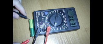
Charging with a laboratory power supply If you have a power supply with current limiting protection, then you are saved! That is, the indicator will light up simultaneously with the battery turning off at the moment of discharge.
As the battery capacity increases, the currents also increase. To get 11.1 V you need to connect three batteries in series. If your battery has a built-in protection board, which was discussed just above, then everything becomes simpler.
Here's how: To set up the circuit, we connect an adjustable power supply instead of batteries and select resistor R2 R4 to ensure that the LED lights up at the moment we need. To avoid unacceptable discharge, connect indicator circuits after the power switch or use protection circuits that prevent deep discharge. Here the current is set by a resistor connected to the 5th pin of the microcircuit. If you charge 3s, take three phone chargers and connect each to one module.
The diagrams presented in the article only indicate low voltage on the battery. Well, the TIP41 transistor can be replaced with any other one with a suitable collector current.
In such cases, a parallel connection of batteries is used to complete the battery. The disadvantage of the circuit is the complexity of selecting zener diodes to obtain the required response threshold, as well as the constant current consumption of about 1 mA. The cheapest way to charge batteries with balancing
Rule 6. At this stage, the charger maintains voltage 4 on the battery.
There is a pre-charge function, see. The USB charging option can be assembled, for example, on such a printed circuit board. Obviously, a battery with 2 times smaller capacity at a current of 2 amperes will take the same amount of energy as batteries with a larger capacity, but the voltage on it will increase approximately three times faster. For LEDs, you should use only red LEDs, since they have the lowest forward voltage during operation. TP4056 - Li-ion battery charging module with charge controller However, coverage of the issue of charging lithium batteries would be incomplete if one more charging stage was not mentioned - i.e. It works very simply. Guyver made a video about this, so don’t waste your time, watch it, it’s about this in as much detail as possible. Before using any of the analogues, check the datasheets.
Welding lithium batteries at home
It is unlikely that a home craftsman will buy a spot welding machine. On AliExpress. The most affordable device costs more than 6 thousand rubles. Therefore, we are looking for a budget-friendly way to install a simple device using improvised means.
At home, 2 types of spot welding are used for lithium batteries, impact and transformer. If a capacitor is used and direct connection of contacts is used, this is impact welding. An example of an impact welding installation is the use of a battery that has served its intended purpose. But the pulse must be milliseconds. In order not to overheat the surfaces being welded, it is necessary to automate the touch time. Get acquainted with the condensate welding scheme.
How to use a transformer to make a converter of ordinary mains current into a welding one, with a voltage of 2-3 V and a power of up to 1000 A. You will need to create a new device using an existing transformer, for example, from a microwave oven, with a power of 1 kW. To do this, you need to remove the secondary winding and magnetic shunts. Wind a new circuit using a well-insulated wire with a cross-section of 35 mm2 and a diameter of 12 mm. It is necessary to perform 2-3 turns to achieve an idle circuit of 2 V and the required current strength. To act with a short pulse, use a controller that controls the triac. Set the current pulse to approximately 35-40 milliseconds. The human reaction does not allow it to fall within this range of influence. Nickel tape is used for connection. The appearance of the device and the operating procedure can be seen in the video.
It is important to use the correct tips when spot welding. They must be made of copper wire with a cross-section of 2-5 mm. But it’s better to take designs from soldering irons. Contacts with the current-carrying sleeve must be tight and not create unnecessary resistance. The diameter of the supply wire is chosen equal to or thicker than the tip. The electrodes are set at the required distance, pressed against the plate, and a current pulse is applied.
Default title
You shouldn’t set a high current right away; first see how hot the microcircuit gets. All stages of charging a lithium-ion battery, including the pre-charging stage, are schematically depicted in this graph: Exceeding the rated charging voltage by 0.15V can reduce the battery life by half. Rule 1. If you log in to the site as a user, you will receive notifications about new materials on the site. So what should a poor radio amateur do? Resistor R1 sets the maximum value of the charging current. Here, for example, is a diagram of the BP-6M battery protection board that was supplied with old Nokia phones: If we talk about, they can be produced with or without a protection board.
Plus there is an indicator of the charging process, as well as an indication of the end of charging. The power of resistor R1 is at least 1 Watt. The charge current is - mA, this value is limited by the internal circuits of the LP chip and depends on the manufacturer. But it is permissible to connect batteries of different capacities in parallel. Serial connection of batteries
There are two options for connecting batteries, series and parallel.
Let's look at how to do this. At this stage, the charge is provided by a direct current of reduced magnitude until the voltage on the battery reaches a value of 2. Basically, batteries are assembled in series-parallel, and the assemblies themselves serve for intermediate or backup storage of electricity. 3 options for connecting individual batteries in battery: series, parallel and mixed or combined. Series connection: When connecting elements in series, the values of their internal resistances are also added up. Then it will look like this, you see, it couldn’t be simpler: a pair of resistors and one conductor: One of the printed circuit board options is available at this link. The balancer includes a TLA zener diode and a single-sided forward conduction transistor BDI 40. Excellent balancers are included in the circuit of chargers for lithium batteries, which are widely used. It will detect the voltage on each cell and turn off the entire assembly if one discharges first. MCP Microcircuit allows you to create the right chargers, moreover, it is cheaper than the promoted MAX If we disassemble the battery from a mobile phone, we will find this simple device inside: This is the battery protection board. This circuit fully implements the two-stage process of charging lithium batteries - first charging with direct current, then moving to the voltage stabilization phase and smoothly reducing the current to almost zero. Hardly. How does current flow through such a circuit when overdischarge protection is triggered?
Now let's say that we discharge the same series circuit. And you can connect the battery. It is difficult to manually set and maintain the above modes on a regular power supply, so it is better to use special microcircuits designed to automate the process of charging the circuit (see this section).
Parallel connection of batteries with formulas Parallel connection is carried out by switching single-pole terminals of current sources: the positive and negative terminals of the previous battery are connected to the same terminals of the next one. If the capacities of the batteries being combined are equal, to find the battery capacity it is enough to multiply the number of batteries composing the battery by the capacity of one battery in the assembly. At this stage, the charge is provided with a constant current of reduced value until the voltage on the battery reaches a value of 2. At the same time, all the prerequisites for overheating and depressurization are created. Let us immediately warn you that charging this type of battery is quite dangerous if done incorrectly.
A similar diagram is shown in the following version. This is how this board is installed in a lithium-ion battery. Then it will look like this, you see, it couldn’t be simpler: a pair of resistors and one conductor: One of the printed circuit board options is available at this link. The battery has discharged below 2.5V. The only thing it can’t do automatically is make a decision to fully charge the battery and turn off. LI-ION protection board - HOW DOES IT WORK?
