In the context of the widespread use of metal, products from which are relevant and in demand in all areas of production, construction, and communications, a wide range of possibilities is used for processing and cutting sheets, pipes, fittings, and profiles. One of them is oxygen-arc cutting, which is used in the dismantling and installation of metal structures, construction and repair of structures, components and mechanisms. The technological operation is accessible and simple, and has a low cost.
Physical principles of cutting
The oxygen-arc cutting method is a physical process of complete or partial separation of metal, which is based on the action of an oxygen jet and an electric arc. The technology is used to work with products up to 120 mm thick, made of carbon steel grades. Unlike arc cutting, the operation uses an oxygen jet, which is supplied to the work area under high pressure and oxidizes the steel alloy, removing combustion products. This technique allows you to expand cutting capabilities by increasing the amount of thermal energy, which speeds up the process and increases cutting efficiency. In hardware, steel tubes with a length of 340 mm to 400 mm and a diameter of 8 mm act as electrodes.
The technological process of metal separation is based on the simultaneous influence of two factors. The metal is heated by an electric arc, and then burned by a stream of oxygen supplied parallel to the electrode. In practice, both consumable tubular and graphite carbon electrodes are used. As the cutting moves, the cutting oxygen jet follows the movement of the electrode, forming a cut.
Plasma cutting
Plasma cutting involves the penetration of the metal being cut due to the heat generated by a compressed plasma arc, and the intensive removal of the melt by a plasma jet.
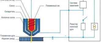
Plasma cutting technology
Plasma is a high-temperature ionized gas capable of conducting electrical current. A plasma arc is obtained from a conventional arc in a special device - a plasma torch - as a result of its compression and injection of a plasma-forming gas into it. There are two plasma cutting schemes:
- plasma arc cutting
- plasma jet cutting
Rice. 6. Plasma cutting diagram
In plasma arc cutting, an arc burns between a non-consumable electrode and the metal being cut (direct arc). The arc column is combined with a high-speed plasma jet, which is formed from the incoming gas due to its heating and ionization under the action of the arc. For cutting, the energy of one of the near-electrode spots of the arc, the plasma of the column and the torch flowing from it are used.
When cutting with a plasma jet, the arc burns between the electrode and the forming tip of the plasma torch, and the object being processed is not included in the electrical circuit (indirect arc). Part of the plasma of the arc column is removed from the plasmatron in the form of a high-speed plasma jet, the energy of which is used for cutting.
Plasma arc cutting is more efficient than plasma jet cutting and is widely used for metal processing. Plasma jet cutting is used less frequently and is primarily used for processing non-metallic materials, since they do not necessarily need to be electrically conductive.
Rice. 7. Plasma cutting
The technological capabilities of the process of plasma cutting of metal (speed, quality, etc.), as well as the characteristics of the main components of plasma torches are determined, first of all, by the plasma-forming medium.
Metal plasma cutting technology
Plasma cutting is economically feasible for processing:
- aluminum and alloys based on it up to 120 mm thick;
- copper up to 80 mm thick;
- alloy and carbon steels up to 50 mm thick;
- cast iron up to 90 mm thick.
The cutter is positioned as close as possible to the edge of the metal being cut. After pressing the torch switch button, the pilot arc is ignited first, and then the cutting arc, and the cutting process begins. The distance between the surface of the metal being cut and the end of the cutter tip must remain constant. The arc should be directed downwards and usually at right angles to the surface of the sheet being cut. The cutter is slowly moved along the planned cutting line. The speed of movement must be adjusted so that sparks are visible from the back of the metal being cut. If they are not visible from the reverse side, then the metal has not been cut through, which may be due to insufficient current, excessive speed, or the direction of the plasma jet not at a right angle to the surface of the sheet being cut.
Plasma-forming gases
Plasma cutting of aluminum and its alloys with a thickness of 5–20 mm is usually carried out in nitrogen, with a thickness of 20–100 mm – in nitrogen-hydrogen mixtures (65–68% nitrogen and 32–35% hydrogen), with a thickness of over 100 mm – in argon- hydrogen mixtures (35–50% hydrogen).
Plasma cutting of copper can be carried out in nitrogen (for a thickness of 5–15 mm), compressed air (for small and medium thicknesses), or an argon-hydrogen mixture.
Plasma cutting of high-alloy steels is effective only for thicknesses up to 100 mm (for larger thicknesses, oxygen-flux cutting is used). For thicknesses up to 50–60 mm, air plasma cutting and manual cutting in nitrogen can be used; for thicknesses over 50–60 mm, nitrogen-oxygen mixtures can be used.
Cutting stainless steel up to 20 mm thick can be done in nitrogen, 20–50 mm thick – in a nitrogen-hydrogen mixture (50% nitrogen and 50% hydrogen). It is also possible to use compressed air.
For cutting carbon steels, compressed air (usually for thicknesses up to 40–50 mm), oxygen and nitrogen-oxygen mixtures are used.
Table 3. Approximate modes of air plasma cutting of metal
We can highlight the following advantages of plasma cutting in comparison with gas methods:
- Higher speed of cutting metal of small and medium thickness
- Versatility - plasma cutting is used for processing steel, aluminum and its alloys, copper and alloys, cast iron and other materials
- Precise and high-quality cuts, while in most cases subsequent machining is eliminated or significantly reduced
Cost-effectiveness of air plasma cutting - there is no need for expensive gases (acetylene, oxygen, propane-butane)
- Ability to cut parts of complex shapes;
- Short pierce time (oxyfuel cutting requires a long preheat)
- Safe cutting as there are no explosive gas cylinders
The disadvantages of plasma cutting compared to gas cutting methods are:
- The maximum cutting thickness is usually 80–100 mm (oxygen cutting can process cast iron and some steels up to 500 mm thick)
- Equipment costs are much higher
- Increased requirements for equipment maintenance
- High noise level due to gas flow from the plasmatron at transonic speeds
- Nitrogen-containing emissions are harmful to the body (when using nitrogen), to reduce which the cut product is immersed in water.
Equipment:
Plasma cutting uses equipment such as a plasma torch, power source, compressor, and gas cylinders.
Equipment and technology
As equipment for implementing the technological operation, special cutters are used, the design of which allows oxygen to be supplied to the cutting site and a special electrode to be secured. The operation is feasible with both direct and alternating current, the magnitude of which depends on the cross-section of the electrode. In this case, the most stable arc is when powered from a direct current source, for the formation of which a fusible wire is used. Oxygen supply is realized through the central channel of the electrode. Its outer part is covered with a special coating, which is necessary for stable arc burning.
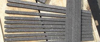
During the technological process, the electrode is placed resting on the surface of the material to be separated at an angle of 75 - 85º with a slope in the direction of cutting. A conventional steel electrode has a length of 350–400 mm, an outer diameter of 5–6 mm with an internal channel cross-section of up to 2 mm. The disadvantages of the technology include the high consumption of such electrodes, the combustion time of which is about 40 - 50 seconds. Tubular-type electrodes made on the basis of boron carbide or silicon have increased durability and resistance. Ceramic electrodes covered with a metal shell with a coating applied on top have a length of 300 mm, a diameter of 12 mm and are characterized by increased cost. With a current of 300 to 500A, their operating time is 30-40 minutes.
In some cases, when working with steel products whose thickness does not exceed 50 mm, the sequential jet method of oxygen-arc cutting technology is used. To do this, cutting equipment is connected to a standard electric holder designed for arc welding, allowing oxygen to be supplied to the surface of the metal molten by the arc. DC or AC units can be used to form an arc. Electrodes of any type can be used as consumables, as well as carbon wire with a cross-section of 5 mm, regardless of brand, with coating. The latter consists of 4 shares of coal slag and 1 share of chalk. The welding current is usually 200 - 250A. The effectiveness of sequential jet technology is comparable to the results of manual oxygen-acetylene cutting.
Depending on the thickness of the metal, the pressure of oxygen supplied to the metal separation zone ranges from 0.3 to 1 MPa. In many ways, the efficiency of both cutting and productivity depends on the purity and quality of the oxygen used for cutting the alloy.
Tweet
Methods of cutting with a consumable electrode.
Arc cutting
is one of the types of separation cutting.
It is based on the melting of metal from the cutting zone by the heat of an electric arc excited between the electrode and the metal being cut. This method is widely used in construction and installation work for rough cutting of metal. Cutting is carried out using steel electrodes with a high-quality coating, but more refractory than for welding. This coating ensures the formation of a small visor during cutting, covering the arc area. The visor protects the electrode from a short circuit to the metal being cut, and also promotes more concentrated heating of the metal and allows for more productive cutting. % manganese % liquid is used as a coating The thickness of the coating is 1... 1.5 mm . Coated electrodes TsM-7 and TsM-7s . Electrodes with a diameter of 4..6 mm are the most recommended. The cutting current is selected within the range of 50...60 A per 1 mm of electrode diameter. The arc power source can be welding generators or welding transformers. Arc cutting is used for cutting metals with a thickness of no more than 30 mm ; productivity is low - when the thickness of the metal being cut is 15 mm, the cutting speed does not exceed 120...150 mm/min . Electrode consumption is 1.0…1.5 kg per 1 m of metal being cut.
Oxygen arc cutting
differs from arc in that a stream of pure oxygen is supplied to a section of the metal surface heated to the point of melting. Oxygen burns through the metal of the cutting area and blows the resulting oxides and molten metal out of the cut cavity. When metal burns, additional heat is released, which speeds up the process of melting and cutting the metal. This method is used to make short cuts in various building structures.
VNIIavtogenmash has developed a method for manual oxygen-arc cutting with an RGD . With this method, the carver holds the electrode holder in his right hand and the cutter in his left. Having excited the arc and heated the metal until it melts, the cutter presses the handle of the oxygen valve and directs a stream of oxygen onto the heated metal, then moves the arc and the cutter along the cutting line. The electrodes are steel rods with a diameter of 4...5 mm coated with TsM-7 , OMM-5 , OZS-Z , etc. The current, depending on the diameter of the electrode, is 160...250 A. This method can cut metal up to 50 mm . Metal with a thickness of 10...20 mm is cut with an electrode with a diameter of 4 mm at a speed of 450...550 mm/min . Oxygen consumption is 100…160 l/min . Carbon and low-alloy steels with a thickness of 50 mm are cut with an electrode with a diameter of 5 mm at a speed of 200 mm/min with oxygen consumption up to 400 l/min .
An important advantage of oxygen-arc cutting is the ability to combine cutting with welding work when installing various building structures.
Methods of cutting with a non-consumable electrode.
The following types of arc cutting with a non-consumable electrode are used: separation cutting with a non-consumable electrode, air-arc cutting and plasma-arc cutting.
Separation cutting
produced by a non-consumable
carbon, graphite or tungsten.
Carbon and graphite electrodes with a diameter of 12...25 mm allow cutting metal up to 100 mm . Cutting is carried out using direct current of straight polarity. The current, depending on the diameter of the electrode, is 40
... 1000 A. During the cutting process, carbon electrodes carburize the cut edges and thereby complicate subsequent machining. Graphite electrodes produce a cleaner cut, last longer, and allow higher current densities. Air arc cutting
Used for both separation and surface cutting. With this method, an arc is excited between a non-consumable electrode and the metal being cut. The heat of the arc melts the metal of the cutting area, and a stream of compressed air continuously removes it from the cutting cavity.
Rice. 1
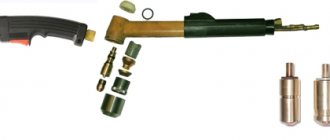
For air-arc cutting of low-carbon and stainless steel up to 20 mm , use the universal cutter RVD-4A-66 (Fig. 1: 1 - electrode, 2 - head, 3 - pressure lever, 4 - body, 5 - cable-hose). It has replaceable carbon electrodes with a diameter of 6... 12 mm . The current reaches 400 A , and in short-term forced mode - 500 A. The air pressure is 0.4…0.6 MPa . Air consumption at a pressure of 0.5 MPa does not exceed 20 m3/h . The weight of the cutter is 1 kg . The cutting process proceeds steadily when the cutter is powered with direct current of reverse polarity. With direct current of straight polarity and with alternating current, the process is unstable, productivity is low and the quality of the cut surface is poor. Cutting performance depends on current. At a current of 200 A, up to 7 kg can be removed in 1 hour , at a current of 300 A - up to 10 kg , and at 500 A - about 20 kg . In addition, with increasing current, the specific energy consumption decreases from 3 kWh/kg at a current of 300 A to 2 kWh/kg at 500 A.
Rice. 2
Plasma arc cutting
is a progressive, high-performance method of cutting metals.
It is carried out by deep penetration of the metal by a compressed arc in the cutting zone and removal of particles of molten metal by a gas flow. In Fig. 2 shows a diagram of the process. The arc is excited and burns between the tungsten electrode 1 and the metal being cut 5 . Constant current of straight polarity. The electrode is located inside a cooled copper mouthpiece 2
. A plasma-forming gas is supplied under pressure into the mouthpiece channel, the jet of which compresses the arc column
3
. Under the action of an arc, the gas heats up to a high temperature, more than
10,000°C , forming plasma. The plasma jet 6
, having a high temperature and high flow rate, melts the metal along the cut line
4 and blows the molten metal out of the cut cavity.
Plasma arc cutting can be used for cutting alloy and carbon steels, cast iron, non-ferrous metals and their alloys. Its most rational and economical use is when cutting high-alloy steels, non-ferrous metals and their alloys. The electrodes are made from lanthanum tungsten VL-15 or thoriated tungsten VT-15 .
Plasma-forming gases are pure argon of the highest grade, technical nitrogen of the 1st grade, a mixture of argon with technical hydrogen, and air.
The arc power sources are single-station welding converters PSYU-500 and rectifiers VKS-500 . , 2…3 are connected in series per arc. Special plasma arc power supplies IPG-500-1 and rectifiers VDG-502 .
The thickness of the metal being cut depends largely on the voltage. For example, with an operating voltage of 75 V, the maximum cutting thickness of aluminum reaches 25 mm , and with a voltage of 250 V - 300 mm . The current is 150...800 A.
Installations in which air serves as the plasma-forming gas are widely used. These include the UPR-201 , designed for manual plasma cutting of metals up to 40 mm at ambient temperatures from +40 to -40 ° C. The installation consists of a power source, cutting process control equipment and a plasma torch. Maximum operating current - 250 A. Air pressure - 0.5.-.0.8 MPa . Air flow - 70... 100 m3/h .
Avov in construction and installation conditions use a mobile installation station KPM-1 , mounted on a single-axle trailer GAPZ-755A . The equipment consists of a welding rectifier VKS-500-1 , a compressor, two ballast rheostats RB-300-1 , a torch GDS-150 , a cutter RDP-2 , cylinders with argon and nitrogen. Ventilation in cutting mode is forced. All post equipment is protected from atmospheric precipitation by a metal casing. The post performs welding of metal up to 2.5 mm and cutting of copper ( up to 20 mm ), steel ( up to 40 mm ) and aluminum ( up to 50 mm ). The mass of the mobile post is 1500 kg .
Share the article with your friends! Let others know about us too!
RќСЂР°РІРёС‚СЃСЏ
Scope of application
Oxygen-arc cutting is most in demand during a complex of assembly and construction works, during which it is necessary to use the cutter in a repeated short-term mode, as well as on objects where the use of oxygen cutting is undesirable or completely unacceptable. In particular, this method is relevant for cutting metal under water. The technology is used for manual cutting of steel; it can be used for separating non-ferrous metals and alloyed alloys with small thickness, cast iron, and for batch cutting of similar products.
Manual oxygen-arc welding allows you to create a cut that is characterized by relatively low quality. Surfaces and edges have irregularities, deposits and roughness. Possessing high productivity and efficiency due to additional sources of thermal energy, the technology is often used during dismantling work, as well as work on grinding scrap metal for its subsequent processing.
Metalworking ordered from our company is carried out in the shortest possible time!
Why do you order oxy-fuel cutting from us:
- Creation of products from 1 hour
- Deferred payment to regular customers
- Payment upon delivery is possible
- Product quality complies with GOSTs, TUs and is confirmed by certificates
Electric arc welding and metal cutting technology
Manual arc welding technology, electrodes
Manual electric arc welding using metal electrodes with protective coating is the most common welding method in the manufacture of pipelines with a nominal diameter of more than 80 mm
with a wall thickness of 3
mm
or more. This welding method is 1.5-2 times cheaper and more productive than gas welding. Manual welding is used mainly at the installation site in conditions where the use of mechanized welding is difficult.
The essence of the method is as follows. The heat required to heat the edges of the metal is obtained by burning an electric arc formed between the metal being welded and the metal electrode. An electric arc melts the base metal and melts the metal rod of the electrode (the arc temperature reaches 3500°C and higher). Molten metal fills the gap between the edges of the parts being welded and, when solidified, joins them into one whole. To form a weld, the electrode is given a complex movement - towards the part, along the seam and across the seam.
Depending on the thickness of the pipe wall, welding of joints is performed in one or several layers (passes). The number of seam layers in manual arc welding depends on the pipe wall thickness:
| Pipe wall thickness, mm | DoZ | 4—5 | 6—9 | 10—12 | 13—15 |
| Number of seam layers | 1 | 2 | 3 | 4 | 5 |
At the welder's workplace (welding station) there must be all the necessary accessories and tools (electrode holder, electrode storage box, portable metal box for cinders, shields and helmets, hammer, chisel, metal brush, as well as a set of templates and probes). The welder must also have a flexible, well-insulated wire of the required length and required cross-section (welding cable).
Shields and helmets serve to protect the eyes and facial skin from the harmful effects of welding arc radiation. They are made from fiber or specially treated plywood; they weigh no more than 0.6 kg.
To observe the arc, there is a rectangular cutout measuring 120x60
mm
for installing protective glasses. Protective glasses (light filters) do not allow ultraviolet and infrared rays to pass through. On the outside, the filter is protected from splashes of molten metal by ordinary transparent glass.
Security measures
Oxygen-arc cutting of metal belongs to the category of work with an increased fire hazard, which is performed by a cutter from among the electrical or electrical technological personnel. To ensure safety, the equipment is inspected at least once a year, and the work site is provided with primary fire extinguishing equipment. The performer must use a protective mask and special clothing during the technological operation.
see also
- Oxygen flux cutting
Air Arc Cutting Safety
All welding work is associated with certain factors that can be harmful to human health.
The main ones include:
- large DC sources;
- molten metal formed during cutting;
- ultraviolet radiation of an electric arc;
- toxic gases and dust generated during the air-arc cutting process.
To protect yourself from the listed factors, you should strictly follow the operating instructions for the equipment and work only in special clothing. The room in which air-arc cutting is performed must be well ventilated. The exception is open construction sites where natural air exchange occurs.
Due to the high power of welding electrical equipment, be sure to check the grounding before turning it on.
|