Home » Reviews » Review of cutting saw machine type 8725
The hacksaw machine type 8725 is produced by the Russian company PromPressMash. The equipment works flawlessly and fully copes with its functions. The machine is used both in individual production, for example in repair shops, and in mass production at large industrial enterprises.
Model 8725 Cutter Manufacturer Information
The manufacturer of the model 8725 hacksaw and cutting machine is PromStroyMash, Orenburg , founded in 2002.
On the Russian construction equipment market there are several domestic developers and manufacturers of hacksaw cutting machines and many foreign companies from China, Turkey, Bulgaria, etc.
Hacksaw cutting machines produced by machine tool enterprises of the USSR, Russia, Belarus:
- 8725 – PromStroyMash, Orenburg
- VSh-042, VSR-042 - Wistan, Vitebsk
- SN1 - Gomel plant of machine components
- MP6-1697 – Machine Tool Plant named after. Kirov, Minsk
- 8725 – Spectrum, Polevskaya, Sverdlovsk region
- 8725 – Krasnodar Experimental Plant named after. Kalinina (SIAL)
- 8715, SM-1 – Klin Machine Tool Plant – Klin Automatic Line Plant (KZAL)
- 8725A, 8725AM – StankoService, Aksai
- 872 – Troitsk Machine Tool Plant, Troitsk
- 8725-22 — Barnaul Machine Tool Plant
- 8B72K, N-1 - Kaunas Machine Tool Plant
Machine tools produced by the Krasnodar Experimental Plant named after. Kalinina
- 8B72
- hacksaw-cutting machine Ø 250 - 872A
- hacksaw-cutting machine Ø 250 - 872M
- hacksaw-cutting machine Ø 250 - 8725
— hacksaw-cutting machine Ø 250
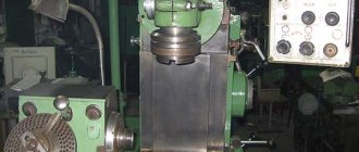
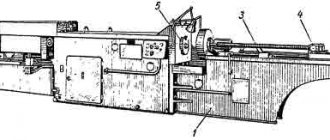
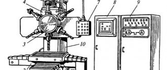
General view of the cutting saw machine 8725
Photo of cutting saw machine 8725
Photo of cutting saw machine 8725
Photo of cutting saw machine 8725
Photo of cutting saw machine 8725
Photo of cutting saw machine 8725
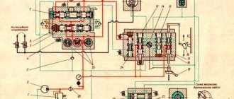
Kinematic diagram of the cutting hacksaw machine 8725
Kinematic diagram of the cutting hacksaw machine 8725
Bearing layout for cutting saw 8725
The machine is driven by an individual electric motor 5, N=3.0 kW, n=960 rpm. The movement of the motor is transmitted through a V-belt drive by pulley 8 to pulley 9, which rotates freely on axis I. The main shaft II can receive 2 revolutions thanks to two stages on the V-belt pulleys.
- n1=55 rpm when transmitting motion from a smaller stage of the electric motor pulley to a larger stage of the pulley on axis I.
- n2=114 rpm when transmitting motion from a larger stage of the electric motor pulley to a smaller stage of the pulley on axis I.
On shaft II, a crank disk 15 is mounted on a key from the pins of the crank 12. From it, by means of a connecting rod 4, the saw frame 2 receives a reciprocating motion with a number of double strokes corresponding to the number of revolutions of shaft II. Bearings 13 and 14 are installed on shaft II, transmitting movement to the pistons 17 and 18 of the hydraulic pump through rods with a hinge.
The pump pistons pump oil through the distribution valve 19 into the working cylinder 20, which is connected to sleeve 3 by means of a rod 23 and two hinges and can rotate it around the axis of sleeve III.
Thus, the raising and lowering of the saw frame 2, the feed during cutting, as well as the lifting of the blade during the reverse stroke is carried out by the hydraulic drive of the machine. Handle 25 serves to control the hydraulic drive. After finishing the cutting, in the lower position of the saw frame, the bar 28 hits the rail 16 and moves it.
Thus, through the gear 27, on the distribution valve 13, the distribution valve is installed in a position corresponding to the lifting of the saw frame, and the hacksaw blade is automatically raised to a height according to the pre-installed switch 22, which presses the limit switch 26.
The electric cooling pump operates when the toggle switch located on the electrical cabinet panel is turned on.
Lubrication chart for 8725 machine.
1-7, 10 — Industrial oil I-20A
8, 9, 11, 12 — Tsitaim-203
The machine is lubricated by the following systems:
— Wick system for lubrication of hose guides, consisting of an oil reservoir 2 located in the upper part of the hose and wicks.
— Periodic grease lubrication system, carried out using grease nipples for lubrication of pulley bearings 8, main shaft 9.12 and pump bearings 11.
— Periodic lubrication system by pouring onto the screw of a vice, connecting rod pins, rods, pump piston pins, rack and drive gear, carried out using a manual oiler.
Brief description of the machine design
Machine drive
Motor 5 (see Fig. 2) is mounted on a frame 6, fixed to the frame 1 with a bracket 7. A V-belt drive pulley 8 is mounted on the motor shaft. A freely rotating second pulley 9 is mounted on axis 1, on the hub of which there is a helical gear 10 z=26, M=2.5, gear 11, z=145, M=2.5, which is mounted on a key on the main gear, engages with this gear. shaft II. The drive gears and pulleys are covered with a casing. The motor is started and stopped using the “Start” and “Stop” buttons.
When the hose is raised to its upper position, switch 22 presses the limit switch and automatically turns off the motor. Screw 33 serves to tension the V-belt drive belts.
bed
The bed (see Fig. 2) 1 has a box-shaped shape with a reinforcing rib inside. The lower part of the frame is a reservoir for coolant. The reservoir for the hydraulic drive oil is made integral with the frame. All components of the machine are mounted on the bed.
Rack
A cast iron stand 24 is mounted on the back side on top of the frame. The stand has sliding bearings for the main shaft II and for the axis III of the pumping arm.
The electrical cabinet is located on the rear side of the rack. On the inside of the stand, a sleeve support 31 is attached to a finger.
Sleeve
Sleeve 3, swinging on axis III, has dovetail-shaped guides on its lower surface along which the saw frame moves.
By means of a rod 23 and two hinges, the sleeve is connected to the piston rod of the working cylinder of the hydraulic drive, which controls the movement of the sleeve.
Saw frame
The saw frame 2 has guides in accordance with the sleeve guides and moves along them in a reciprocating motion from the crank disk 15, to which it is connected by a connecting rod 4.
Hacksaw blade 32 with one of its holes is put on the pin of a fixedly reinforced bar, and with the other hole on the pin of the movable bar and the special one is pressed. slats.
The tension of the hacksaw blade is carried out by a nut.
Clamping vice
To secure the material being cut, the machine is equipped with special clamps with flat grooved jaws.
Clamping is done using a screw and a stop.
Material stop
When cutting small workpieces of equal length, a stop 34 is used, which can be set in the desired position.
Electrical equipment of machine 8725
Electrical equipment consists of:
1) asynchronous AC motors and a limit switch located on the machine;
2) control and protection equipment located in an electrical cabinet installed on the rear wall of the rack;
3) controls located on the electrical cabinet.
Relay devices are installed on panels in the cabinet.
All wiring is done in bundles along the control panel and in metal hoses.
* Installed upon request of the work order.
The main drive electric motor M1 and the cooling pump electric motor are started by pressing the “Start” button, which closes the coil circuit of the magnetic starter, transferring its self-power.
The main drive electric motor and the cooling pump electric motor are stopped by a limit switch.
Protection against short-circuit currents of the main drive motor, cooling pump motor, control circuits and local lighting is carried out by a single-pole circuit breaker.
Protection of electric motors from long-term overloads is carried out by a thermal relay.
At the request of the work order, a local lighting lamp is installed. It is turned on by a switch.
Protection of local lighting circuits from short circuit currents is carried out by a single-pole circuit breaker.
Hydraulic drive of cutting saw machine 8725
Hydraulic drive of cutting saw machine 8725
Hydraulic drive of cutting saw machine 8725
Using a hydraulic drive (Fig. 3), the hacksaw blade is raised and lowered.
The canvas can be installed at a constant height.
When cutting, at the beginning of the working stroke, the pressure of the blade on the material being cut is minimal, then it gradually increases and drops shortly before the end of the working stroke. During the reverse stroke of the saw frame, the hacksaw blade rises and does not come into contact with the material being cut.
Depending on the type of material, the feed amount is smoothly adjusted by throttling the oil.
The maximum oil pressure is determined by the strength of the hacksaw blades and is set by a safety valve.
All control of the hydraulic drive is carried out by a crane 19 with a handle 25. The handle 25 with a pointer 60 moves on a scale 61, equipped with the inscriptions: “Lifting”, “Lowering”, “Inaction”, “Slow action”, “Faster”, which sets the operating mode of the hacksaw canvases ranging from minimum to maximum.
The hydraulic drive housing 62 is mounted on the glass 1 and enters the oil reservoir 34. Oil and the reservoir are filled through hole 63, for which it is necessary to unscrew the plug 75. The oil indicator 85 has a line on the glass corresponding to the normal oil level. The oil is released through a hole in the glass, closed with plug 59.
In the hydraulic pump body, 2 inclined cylinders 66 and 67 are bored out with bimetallic bushings pressed into them. Pistons 17 and 18 of cylinders 66 and 67 receive movement through rods 72 and 73 from bearings 13 and 14 sitting on shaft II. Pistons 17 and 18 suck oil from reservoir 34 through filter 68 and pump it through the channels of valve sleeve 74 and valve plug 19 into working cylinder 20.
The piston rod 78 is pivotally connected to the rod 23 with the sleeve 3 and controls its movement. The tap plug 19 is turned by handle 25. When cutting is completed, the tap plug is automatically set to the “Lifting” position and the hacksaw blade rises. The seal in the tap is achieved by tightening the nut 75.
To set the safety valve 58 to the desired pressure, the degree of compression of the spring 79 is adjusted by screw 80.
Channel 81 serves to supply oil to the control pressure gauge and must be closed with plug 82 when the machine is operating. Safety valve 58 must be adjusted to a pressure of at least 25 atmospheres.
When adjusting the valve, a control pressure gauge is screwed in instead of plug 82.
Description of the hydraulic drive circuit
In Fig. 4, 5, 6, 7, 8 show diagrams of the hydraulic drive of the machine for the main positions of the crane.
1st position “Inaction” (drawing No. 3). In this position, the sleeve connected to the piston 78 of the working cylinder 20 is motionless.
Oil from the upper cavity of cylinder 20 exits through channels 103, 91, 92, 109, and 93 into the reservoir and through channels 103, 90, 89 and 88 and cylinder 67, since at this moment the piston 17 moves up and sucks in oil.
2nd part of the reverse idle movement of the saw frame.
In the 2nd part of the return stroke, piston 18 and then piston 17 change direction of movement and piston 78 is lowered.
1st part of the working stroke of the saw frame.
Immediately after the start of the working stroke, the hacksaw blade comes into contact with the material being cut and with further movement of the frame, the blade receives a feed in the following way: piston 17, continuing to move downward, pumps oil into the upper cavity of the cylinder 20. Pressure from piston 78 in the upper cavity is created by throttling the excess volume of oil discharged into the reservoir through channels 91, 92, throttling channel 109 and hole 93.
Oil from the lower cavity of the cylinder 20 has an outlet into the reservoir through channels 83, 84, 97, 96 and 95, 108, 110 and 111, since the piston 18 in this part of the stroke is located above the hole 108 and cylinder 66.
2nd part of the working stroke of the saw frame.
In the second part of the power stroke, piston 18 changes direction of movement and begins to pump oil, since piston 18 is located above channel 108, the pumped oil is discharged through channels 108, 110 and 111 into the reservoir.
Shortly before the end of the working stroke, piston 17 also changes its direction and begins to suck. Immediately after this, piston 18 closes channel 103 and begins to pump oil through channels 95, 96, 97, 84 and 83 into the lower cavity of cylinder 20. Piston 78 moves upward. The hacksaw blade is raised above the material being cut.
5th position – “Fast action”
The pressure from above on the piston 78 in the 4th position is insignificant, since the pressure difference in the throttling channel 109 is insignificant. When the handle of the valve plug is rotated clockwise from the 4th position, the cross-section of the throttling channel 109 gradually narrows and the pressure from above on the piston gradually increases. In the 5th position, obtained by turning the handle 135° clockwise from the 4th position, the cross-section of the throttling channel is reduced to zero. The excess oil volume now flows through the safety valve 58 into the reservoir. The maximum pressure to which safety valve 58 is adjusted should not exceed 25 atm. and is installed according to control pressure gauge 112.
Diagram of the hydraulic drive of the hacksaw machine 8725. 1st position “Inaction”
Diagram of the hydraulic drive of the hacksaw machine 8725. 2nd position “Lowering”
Diagram of the hydraulic drive of the hacksaw machine 8725. 3rd position “Lifting”
Diagram of the hydraulic drive of the hacksaw machine 8725. 4th position “Lowering slowly”
Diagram of the hydraulic drive of the hacksaw machine 8725. 5th position “Action quickly”
Location of controls
- Input switch.
- Control button “Start” of the machine drive
- Handle for fixing the saw frame in the upper position
- Handwheel for manual movement of the vice
- Hydraulic drive control handle
- The automatic shutdown of the machine is in the upper position of the saw frame.
- Control button “Stop” of the machine drive.
The movement from the electric motor 1 is transmitted through a V-belt transmission and two stepped pulleys to the drive shaft 11. Pulley 4, freely rotating on shaft 11, is interlocked with gear 3. Through a gear pair 3 and 5, the movement is transmitted to shaft 111 at the other end of which a crank disk 10 is attached finger 9. The saw frame receives reciprocating motion from the crank disk through connecting rod 13. Its movement frequency per minute is 120 (1st stage) and 48 (11th stage). To obtain the frequency of movement of the saw frame 62 (111 stage) and 94 (1V stage), it is necessary to reinstall the drive pulley 2 by turning it 180. On the shaft 111 between the two supports there are eccentric journals, from which the movement is transmitted by connecting rods to the pistons A and B of the hydraulic pump. The pistons pump oil into the distribution valve D, from where it flows to the working cylinder C. The piston of this cylinder is connected to the sleeve using articulated rods. Thus, the lifting and launching of the dusty frame, as well as the working feed during cutting, is carried out from a hydraulic drive.
Hydraulic circuit diagram of machine 8725
The hydraulic drive of the hacksaw machine 8725 is controlled by handle E, which can be locked in the following positions: 1-“Inaction”, 11-“Lowering”, 111-“Lifting”, 1V-“slow cutting” and “Fast”. Upon completion of cutting the workpiece in the lowest position of the saw frame, the bar K, attached to the saw frame, strikes the rail 6 and moves it. The rack, through the intermediate gear 7, transmits movement to gear 8, which is rigidly connected to the shaft of the distribution valve. In this case, the crane is installed in the saw frame lifting position. The saw frame rises until it presses the limit switch. This opens the electrical circuit, turning off the main drive motor.
All hydraulic equipment of the machine is mounted in the pump housing. Piston pumps 1 and 2 suck oil from the oil reservoir through filters 6 and 7, check valves 9 and 10, located in the control valve body, and supply oil to the distribution valve through channels 15 and 16.
Regulation I - "Inaction"
When the valve is installed in this position, the piston pumps run idle, the oil flows through the grooves of the valve into the reservoir through channel 20. The machine sleeve remains motionless in any position. A saw frame with a hacksaw blade can only have a reciprocating motion along the sleeve.
Position II - “Lowering”
In this position, the piston pumps also operate at idle, but the oil from the rodless cavity of cylinder 3 through channel 17 and the grooves of the valve is drained into the reservoir through channel 20. The sleeve and saw frame smoothly lower down.
When the machine is operating, there are two positions in the working cycle: “Lifting” and “Cutting”.
Position III - “rise”
When installing the faucet handle in this position, the oil pumped by piston pumps through channels 15 and 16, the grooves of the faucet and to channel 17 is supplied to the lower cavity of cylinder 3. The hose and the saw frame with the hacksaw blade rise to the upper position. In the extreme position of the saw frame, the lower edge of the piston of cylinder 3 slightly opens a groove in the cylinder, through which excess oil is read through channel 18, tap grooves and channel 20.
Position IV - “Cutting”
In this situation, two stages of work should be considered:
- feeding of the cutting tool during the working stroke of the saw frame with the hacksaw blade;
- undercutting, that is, lifting the cutting tool above the workpiece being cut during the idle motion of the saw frame with the hacksaw blade.
Coordination of the reciprocating motion of the saw frame of the hacksaw machine 8725 and the initial movement of the sleeve is ensured by the fact that the crank disk, which drives the saw frame, is mounted on a shaft with eccentric journals located at an angle of 125° to each other and transmitting movement to pistons 1 and 2. Value supply is regulated by turning the handle of a variable-section valve connecting the cavities of the piston 1 and the rod cavity of the cylinder 3 with drainage through channel 20. Depending on the position of the handle, the amount of oil entering the rod cavity of the cylinder 3 is regulated. Slow cutting is carried out with the throttle open, which corresponds to the upper position handles. Most of the oil is drained through the throttle slot, and the rest enters through channel 18 into the rod cavity of cylinder 3. Fast cutting is carried out with the valve handle turned and the throttle closed. In this case, the throttle is completely closed and all the oil is pumped into the rod cavity of cylinder 3, creating maximum feed to the hacksaw blade. Excess oil is drained through safety valve 4. The cutting tool is lifted above the workpiece at idle when piston 2 moves downwards. Before the side hole in the piston 2 cylinder is closed, the oil is drained through it through channels 19 and 20 into the reservoir. After the piston closes this hole, the oil flows through channels 16 and 17 into the rodless cavity of cylinder 3 and the saw frame with the hacksaw blade is raised. Adjustment of the amount of undercut is carried out by changing the length of the rod between the crankshaft and the piston due to the threaded connection of the hinge bolt screwed into the bearing housing
Bed.
The bed has a box-shaped shape; the main components of the machine are mounted on it (Fig. 2). The lower part of the frame contains a reservoir for cooling liquid. An electric cooling pump is also installed here. The oil reservoir for the hydraulic drive is cast together with the frame.
Drive unit.
The drive of the hacksaw machine 8725 consists of the following main parts: rack; sleeves and saw frame. The stand, mounted on the upper plane of the frame, on the right side, serves as a support for the sleeve and the drive shaft. The lower part of the sleeve has dovetail-type guides along which the saw frame moves. By means of a rod and two hinges, the sleeve is connected to the piston rod of the working cylinder of the hydraulic drive, which controls its movement. When the sleeve is raised to the upper position, the stop presses the limit switch and the electric motor automatically turns off. The saw frame carries out a reciprocating movement from the crank disk, with which it is connected to the connecting rod. The hacksaw blade is installed with one hole on the pin of a fixedly fixed bar, and the other - on the pin of the movable bar and is pressed with special bars. Before clamping the hacksaw blade, a bolt and nut are inserted into the grooves of the movable bars to tension the hacksaw blade. The speed range of 17, 22.34 and 43 m/min provides for cutting workpieces depending on the structure of the material being cut.
Fencing.
All rotating elements of the machine drive are protected by a casing mounted on the frame.
Vise.
To cut material of various profiles (square, rectangular, round), two strips, pos. 6 (see Fig. 5), which allow cutting workpieces of 25...250 mm. The right jaw 1 is fixedly fixed on the machine bed. The workpieces are clamped by moving the left jaw 2, rotating the steering wheel 5 through the nut 4 and screw 3.
Cooling.
To cool the hacksaw blade, the machine has a cooling system consisting of a coolant reservoir, an electric pump, a hose and a special nozzle through which coolant is supplied to the cutting zone.
Maintenance and care of the machine
The machine is sent to the factory adjusted and tested on the fly.
Before putting the machine into operation, it is necessary to set the saw frame to the required number of double strokes. When cutting hard metals, the hacksaw is given 55 strokes/min. When cutting soft – 114 stroke/min. About 10 liters of Industrial I30 oil are poured into the machine hydraulic drive oil reservoir. The oil level is monitored using the oil indicator.
It is necessary to check the lubrication of the machine, replenish the oilers with oil and add oil to the drive gears. The coolant is poured into the lower part of the frame, which serves as a reservoir. The amount of coolant is about 20 liters. A good coolant is 6-10%; solution of "Emulsol" in water. The vice is installed on the machine in such a way that the axis of the workpiece being cut comes in the middle of the saw frame stroke. When installing the material and securing it with a vice, you must ensure that the workpiece lies horizontally and at an angle to the hacksaw blade. Particular attention should be paid to the condition of the hacksaw blade. The canvas must be stretched, its teeth must be sharp.
A loose blade will make an incorrect cut, and a blade with dull or broken teeth will work unproductively and give a poor cut with an uneven surface, and may break if the metal is tough.
Before starting to work on the machine, it is necessary to run the machine idle for a short time in order to remove the air in the cylinders and channels of the hydraulic drive. Air from the plug 82 is released when it is not completely unscrewed when starting the machine, since the machine sleeve is in the lower position, the handle 25 of the hydraulic drive valve is placed in the “Lift” position and then the motor is turned on by pressing the “Start” button. After the air has been removed and the hydraulic drive shows normal operation in all positions, the crane handles can be used to operate the machine.
When starting the machine, place the crane handle in the “Lowering” position and turn on the motor. After the blade is lowered to the material being cut, the crane handle is moved to the “Slow Action” position for preliminary cutting. Then use the same handle to set the desired feed.
Further operation of the machine occurs automatically. At the end of the cutting, the saw frame bar, hitting the rail 16, moves the handle 25 to the “Lifting” position. The saw frame rises and the machine stops. The position of rack 16 relative to the gear sitting on the valve plug is set by the factory and cannot be adjusted. The position of switch 25 relative to the sleeve is set with two screws. For normal operation of the machine, it is necessary to use clean mineral oil, free of acids and other impurities, for the hydraulic drive and lubrication. The coolant should not be contaminated or clogged with small metal particles and should be filtered or replaced periodically. The electrical part should be free of dust, dirt and especially oil.
The ball bearings of the motor must be lubricated with an acid- and alkali-free grease, which is changed periodically. Bearings must be thoroughly washed with gasoline before filling them with lubricant. All wire connections must be strong and reliable. Loose contacts must be tightened, and their surface must be thoroughly cleaned of the layer of oxides.
The temperature conditions of the workshop in which the machine is to operate must be from +15° C and above (according to UHL4).
Adjustment of wear parts
- 1. Wear of the saw frame guides is compensated by moving the movable wedge of the saw frame by tightening the screw.
- 2. Wear of the valve plug 19 and the valve bushing is compensated by tightening the nut 75 until the desired seal is obtained.
Malfunctions in the operation of the machine and methods for eliminating them
When cutting, the machine shows low productivity:
- check the seal in the tap and eliminate the leak;
- check the seal in the plugs that seal the channels in the hydraulic pump housing;
- adjust the safety valve.
Safety precautions when working on a type 8725 machine
To operate the machine safely, the manufacturer strongly recommends following safety precautions. Thus, it is prohibited:
- remove any barriers;
- stand close and grasp the hydraulic drive control handle to avoid being hit when the hydraulics automatically switch to lift;
- measure the cutting thickness on workpieces.
From a safety point of view, when the arm is raised to its upper position, the switch presses the limit switch and automatically turns off the motor.
Cutting saw tools 8725
Dimensions of hacksaw blades
Cutting the material on hacksaw machines is done with hacksaw blades, which are made of steel P9, P18 or ШХ 15.
Hacksaw blades are selected according to the length and pitch of the teeth, depending on the size of the workpiece being cut and the material. The main dimensions of hacksaw blades are given in table. 69.
The pitch of the teeth of hacksaw blades is selected depending on the thickness of the workpiece being cut and its material. Hacksaws with fine teeth are used for cutting thin workpieces and hard materials, hacksaws with large teeth are used for workpieces with large cross-sections and soft materials.
Thus, when cutting steel σвр = 40-60 kg/mm2 with machine hacksaws, hacksaws with a tooth pitch of 3..4 mm are recommended, steel σвр = 60 kg/mm2 - with a pitch of 2.5 mm.
Tooth shape of hacksaw blades
Typically, the tooth shape of hacksaw blades is triangular (Fig. 27).
For machine-made hacksaw blades, the rake angle is γ = 0–5°, the rear angle is α = 35–40°, the sharpening angle is β = 50–55°, and the radius of the depressions is 0.5–1.5 mm. The All-Union Scientific Research Instrumental Institute recommends a symmetrical tooth with a rake angle γ = - 30° and a sharpening angle β = 60°
These hacksaw blades have less tooth wear, increased productivity and, when dull, can be additionally used by installing the other end.
To reduce lateral friction, the teeth of the hacksaw blades have a set of 0.6-0.8 mm. The difference in the height of the tops of adjacent blade teeth should not exceed 0.1 mm for blades with a tooth pitch of 1 mm and 0.15 mm for blades with a tooth pitch of more than 1 mm.
The performance of hacksaw machines depends on the pressure on the blade, which is recommended to be selected depending on the thickness of the blade. Thus, with a hacksaw blade thickness of 0.8, 1 and 2 mm, the pressure is 5, 10 and 30 kg, respectively.
During operation, the blade must be tightly stretched on the frame; after several strokes of the saw, it is necessary to tighten the blade a second time.
Diagram of the components of the 8725 machine
| 1. Bed | 18. Hydraulic pump piston |
| 2. Saw frame | 19. Distribution tap |
| 3. Sleeve | 20. Working cylinder |
| 4. Connecting rod | 21. Switch |
| 5. Electric motor | 23. Traction |
| 6. Frame | 24. Cast iron stand |
| 7. Bracket | 25. Handle |
| 8. V-belt pulley | 27. Gear |
| 9. Pulley | 28. Plank |
| 10. Helical gear | 29. Electric pump |
| 11. Gear | 31. Sleeve support |
| 12. Crank pin | 32. Hacksaw blade |
| 13. Bearing | 33. Preload screw |
| 14. Bearing | 34. Emphasis |
| 15. Crank disk | |
| 16. Rake | |
| 17. Hydraulic pump piston |
Technical characteristics of mechanical hacksaw 8725
| Parameter name | 872a | 872m | 8725 | 8B72 |
| Basic machine parameters | ||||
| Largest cross-sectional dimensions of a round workpiece (cut angle 90°), mm | 250 | 250 | 250 | 250 |
| The largest cross-sectional dimensions of a round workpiece (cut angle 45°), mm | 120 | 100 | 140 | 140 |
| Largest cross-sectional dimensions of a square workpiece (cut angle 90°), mm | 250 x 250 | 250 x 250 | 250 x 250 | 250 x 250 |
| Largest cross-sectional dimensions of a rectangular workpiece (cut angle 45°), mm | 120 x 120 | 100 x 100 | 140 x 250 | |
| The greatest distance from the canvas to the upper part of the frame, mm | 223 | 223 | ||
| Maximum length of the workpiece to be cut along the stop, mm | 350 | 350 | 350 | 350 |
| Distance from the base of the machine to the supporting surface of the workpiece, mm | 550 | 450 | ||
| Dimensions of the hacksaw blade used (LxWxThickness), mm | 500 | 450 | 450x40x2; Ø 8 | 500x40x2; Ø 8 |
| Maximum cutting width, mm | 2,5 | 3,8 | 3,5 | 3,8 |
| The number of double strokes of the saw frame per minute | 85; 110 | 85; 110 | 45, 56, 71, 112, 140, 128 | 75, 120 |
| Saw frame stroke length, mm | 150 | 140, 180 | 180 | 140, 180 |
| Angle of rotation of the vice, degrees | 45° | 45° | 45° | 45° |
| Productivity when cutting steel 45 GOST 1050-74 Ø 100mm, not less than cm2/min | 30 | |||
| Workpiece clamping mechanism | manually | manually | manually | |
| Electrical equipment of the machine | ||||
| Main drive electric motor, kW (rpm) | 1,7 | 1,5 (1420) | 2,2 | 1,5 (1400) |
| Cooling pump electric motor, kW (rpm) | 0,12 | 0,125 (2800) | ||
| Dimensions and weight of press shears | ||||
| Dimensions of press shears (length x width x height), mm | 1470 x 875 x 925 | 1470 x 690 x 885 | 1690 x 700 x 900 | 1610 x 700 x 900 |
| Weight of press shears, kg | 605 | 650 | 700 | 645 |
- Hacksaw machine 8725. Operating manual 8725.00.001 RE, Plant named after. M.I. Kalinina, Krasnodar, 1975
- Veselovsky S.I. Cutting materials, 1973
- Drozdov F., Lebedevich V., Rubezhin V. Reference manual on cutting machines, 1967
Bibliography:
Related Links. Additional Information
- Manufacturers of forging and pressing equipment in Russia
- Classification and designation of hydraulic and crank presses
- Mechanical presses
- Hydraulic presses
- Automatic forging and pressing machines
- Bending and straightening machines
- Guillotine shears, press shears
- Hammers
- Repair of hydraulic systems of metal-cutting machines
- Designations of hydraulic circuits of metal-cutting machines
- Repair of gear hydraulic pumps
Home About the company News Articles Price list Contacts Reference information Interesting video KPO woodworking machines Manufacturers
Features of the hacksaw machine 8725:
- Climatic modification according to GOST 15150-69-UHL4.
- The vice is equipped with a special bracket for securing workpieces.
- The saw frame is driven by a separate electric motor through a crank mechanism. The wire pulleys are made of two stages so that the number of double strokes can be varied.
- Raising and lowering the saw frame, feeding the hacksaw blade during cutting, and lifting the saw frame during the reverse stroke are carried out using a hydraulic drive. The saw frame returns to the top position at the end of cutting automatically.
- Coolant is supplied to the hacksaw blade during the cutting process.
- Machine accuracy class – N according to GOST 8-82E