Information about the manufacturer of horizontal boring machine 2A622
Manufacturer of horizontal boring machines 2A622 Leningrad Machine Tool Plant named after. Sverdlov , founded in 1868.
Since 1949, it has been a heavy machine tool manufacturing enterprise. Began producing metal-cutting machines of his own design (horizontal boring, jig boring, copy milling, machining center type, etc.
In 1962, the Leningrad Machine Tool Production Association was created on the basis of the plant.
The association has a closed technological cycle, has foundry, procurement, galvanic production, all types of mechanical processing, bench assembly of machines, painting and packaging areas.
In 2003, bankruptcy proceedings were initiated against the company
In 2004, the plant went bankrupt. The trademark was sold to Kirov-Stankomash, LLC
Machine tools produced by the Leningrad Machine Tool Plant named after. Sverdlova
- 2A470
- two-column jig boring machine of especially high precision 1400 x 2240 - 2A614
- universal horizontal boring machine Ø 80 - 2A620
- universal horizontal boring machine Ø 90 - 2A620F1
- universal horizontal boring machine Ø 90 - 2A622
- universal horizontal boring machine Ø 110 - 2A622F1
- universal horizontal boring machine Ø 110 - 2A622F4
- CNC horizontal boring machine Ø 110 - 2A656F11, 2A656RF11
- heavy universal horizontal boring machine with a movable stand Ø 160 - 2B460
- two-column jig boring machine 1000 x 1600 - 2V622F4
- CNC horizontal boring machine Ø 125 - 2E460
- two-column jig boring machine 1000 x 1600 - 2E470
- two-column jig boring machine 1400 x 2240 - 2E656, 2E656R
- heavy universal horizontal boring machine with a movable stand Ø 160 - 262G
– universal horizontal boring machine Ø 85 - 2620, 2620A
- universal horizontal boring machine Ø 90 - 2657
— universal horizontal boring machine Ø 150 - 6441B
- horizontal copy-milling machine with electronic control 630 x 1200
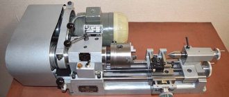
2A622 Horizontal boring machines with a fixed front stand. Purpose, scope
Horizontal boring machines 2A622 replaced outdated machines of the 2622 models.
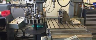
2A622 machines are designed for cantilever processing of various large body parts weighing up to 4000 kg, having precise holes, the axes of which are interconnected by precise dimensions.
2A622 machine is equipped with a fixed front stand and a built-in rotary table that has longitudinal and transverse movement relative to the spindle axis.
2A622 machines you can drill, countersink, boring and reaming precise holes according to exact coordinates, milling and threading.
The design of the machines allows milling along an octagonal contour with two feeds: transverse - table and vertical - spindle head, as well as milling with a circular table feed.
Design and operational features of the machines:
- boring spindle with hard nitrided surface in long-length hardened steel bushings;
- increased rigidity and vibration resistance of the spindle;
- mechanized tool clamping;
- ball screws;
- lateral rolling guides hardened by high-frequency currents for moving units;
- special precision rolling support of the rotary table;
- automatic table rotation through 90°;
- automatic clamping and pressing of the moving parts of the machine on the guides;
- pendant hard electric control panel;
- telescopic protection of guides;
- electric steering wheel for precise installation of moving parts with sensitivity up to 0.005 mm;
- centralized, automated lubrication of guides;
- thyristor feed drive.
2A622 machines can be equipped with various numerical control systems, both domestic and foreign.
Modifications of horizontal boring machine 2A622
Machines models 2A622, 2A622F1, 2A622F2 with a retractable spindle with a diameter of 110 mm and a fixed plate on the end wall of the spindle head are characterized by increased rigidity and vibration resistance of the spindle system and are recommended for high-performance cantilever processing.
Using a removable faceplate, you can grind end surfaces and bore large holes. 2A622, 2A622F1-1 - horizontal boring machines produced by the machine tool industry
2A622-2, 2A622F1-2 - horizontal boring machines produced by Charentsavan Machine Tool Plant
- The machine model 2A622-1 is equipped with an optical coordinate reference.
- The machine model 2A622F1-1 is equipped with a digital coordinate display.
- The machine model 2A622F2-1 is equipped with a numerical control system.
Machine accuracy class N.
In 1975, machine tools of models 2A622-1, 2A622F1-1 were awarded the “Quality Mark”.
- home
- Catalog
- Horizontal boring machines
- Horizontal boring machine 2A622
Horizontal boring machine 2A622
Horizontal boring machine 2A622 – Vega-Prom
Buy in cart
RUB 11,300,000
Article: 110541
Horizontal boring machine 2a622 produced by the Leningrad Machine Tool Plant named after. Sverdlov USSR. The plant operated successfully, producing not only GDS, but also launched the production of jig boring and copy milling machines. It was cool in those years (Soviet machining center). The enterprise had its own closed cycle, supplying not only the entire Union, but also exporting. Everything was great, but new policies, new people and the plant were gone. In 2003, bankruptcy proceedings began. 2004 The Kirov-Stankomash plant acquired the trademark and that was all.
These machines are still in high demand today, since foreign analogues are too expensive. When modernizing machines of this class, transferring them to modern CNC controls from both Russian and foreign manufacturers, it allows us to achieve efficiency and manufacturability that meet modern requirements. After modernizing the old fleet, you can buy a boring machine at 50% cheaper than imported ones.
— Milling along an 8-angle contour with two feeds (horizontal - with a table, vertical - with a spindle head); — Milling with circular table feed; -Spindle with hard nitrided surface;
-High rigidity, vibration resistance;
-Mechanical tool clamp;
- Availability of ball screw;
-Table rotation through 90 degrees;
-Clamping and pressing of the moving parts of the machine on the guides - automatic;
-Control panel - pendant or remote on a separate stand;
-Telescopic protection of guides;
-Electric steering wheel (setter) for precise positioning of moving parts with sensitivity up to 0.001 mm;
- Lubrication of guides is automated;
| Parameter | Meaning |
| Diameter of retractable spindle, mm | 110 |
| Main drive power, kW | 8.5 |
| Spindle rotation speed, min-1 | 10 — 1 250 |
| Faceplate rotation speed, min-1 | 6,3 — 160 |
| Maximum moment on the retractable spindle, Nm | 3 000 |
| Faceplate diameter, mm | 630 |
| Dimensions of the rotary table, mm | 1 250 x 1 120 |
| Number of spindle speeds | 23 |
| Number of faceplate rotation speeds | 15 |
| Maximum moment on the faceplate, Nm | 2 500 |
| Spindle taper design | Morse 6 |
| Table transverse movement (X), mm | 1 000 |
| Headstock vertical movement (Y), mm | 1 000 |
| Table longitudinal movement (Z), mm | 1 200 |
| Spindle longitudinal movement (W), mm | 710 |
| Feed force of spindle head, N | 20 000 |
| Spindle feed force, N | 15 000 |
| Table feed force, N | 20 000 |
| Rotary table - rotation (V), deg | 360 |
| Feed limits of spindle headstock and table, mm/min | 1,25 — 1 250 |
| Radial caliper feed limits, mm/min | 0,8 — 800 |
| Load capacity of the table, kg | 3 000 |
| Working feeds along linear axes, mm/min | 2 — 2 000 |
| Discreteness of movement assignment, mm | 0,001 |
| Accuracy class according to GOST2110 | Normal |
| Overall dimensions in standard version (L x B x H), mm | 6,790 x 4,880 x 3,100 |
| Total weight of the machine 2A622, kg | 16 000 |
Similar products
- Horizontal boring machine 2A614
Article: 110551RUB 8,880,000
Add to cart In cart
- Horizontal boring machine 2A620
Article: 110540
RUB 8,150,000
Add to cart In cart
Photo of horizontal boring machine 2A622
Photo of horizontal boring machine 2a622
Photo of horizontal boring machine 2a622
Photo of horizontal boring machine 2a622
Photo of horizontal boring machine 2a622
Location of controls for horizontal boring machine 2A622
Location of controls for horizontal boring 2a622
List of controls for horizontal boring machine 2A622
- feed rate selection handle;
- selection of spindle speed;
- spindle movement count dial;
- steering wheel;
- helm console;
- caliper movement count dial;
- tool spin;
- tool clamp.
Main console of horizontal boring machine 2A622F4
Main console of horizontal boring machine 2a622f4
- S12 - Emergency button ALL STOP
- — Remote control panel for CNC correction
- H25 - Select Node B
- H24 - W node selection
- H23 - Z Node Selection
- H22 - Y node selection
- H21 - Select node X
- S135 - Select node B
- S134 - W node selection
- S133 - Z node selection
- S132 - Y node selection
- S131 - Select node X
- S15 — Feed variator
- S19 - Operator for controlling feed units
- S136 - Turning on the working feed in the “+” direction
- S137 - Turning on the working feed in the "-" direction
- S156 - Recording frame with positioning
- S157 - Recording frame with feed
- S36 - STOP feed
- S143 - STOP spindle rotation
- — Remote CNC control panel
- H26 - Automatic operation
- H34 - The CNC is not ready for operation
- H35 - No power supply to thyristor converters
- H36 - Hydraulic unit faulty
- H33 - Chiller malfunctions
- H27 - Filter clogged
- H87 - Hitting emergency limit switches
- S16 - Main drive speed variator
- S151 - Turn on the coolant pump
- S13 - Turning on the machine lighting
- S144 - Enabled non-clockwise spindle rotation
- S119 - Turn on lubrication
- S146 - Enable jog rotation of the spindle clockwise
- S145 - Enable counterclockwise spindle rotation
- S147 - Enable counterclockwise jog rotation of the spindle
- S152 - Turn on the hydraulic power station
- S148 - STOP spindle rotation
- S153 - STOP hydraulic station
- S52 - Travel speed control
- S54 - Spindle speed range selection
- S51 - Selecting the direction of movement of units, feed and rotation of the spindle
- S185 — Switch for selecting operation from the main or portable remote control
Alarm lamps
Buttons
Alarm lamps
Buttons
Switches in setup mode
- S159 - Working with a faceplate
- S158 - working with a milling head
Control of horizontal boring machines 2A622
All the main starting controls are concentrated on the main console. In addition to the main console, the machine has several other places for operational control of the machine:
- on the spindle head there is a speed switching mechanism, a mechanism for selecting the feed rate, a button for turning on the steering wheel, a handle for turning on the faceplate and a handle, the activation of which makes it possible to move the faceplate support from the steering wheel when cutting threads with a table;
- on the lower sled tables there is a finishing operator on a flexible hose for fine installation of moving units;
- Optical reading devices have buttons for turning on the optics lighting.
Descriptions of the digital display control panel and the numerical program control device panel are given in the second part of the operating manual.
Controls on the main console
Work body voter
The selector is designed to select the working element and is a push-button switch.
When you select an organ by pressing a button, the organ corresponding to the previously pressed button is pressed.
When you press the button, the electrical circuit of the drive of the selected organ is prepared to turn on and the selected organ is pressed.
Installation Motion Operator
The operator is designed to control the installation movements of the moving parts of the machine.
The operator performs the following functions:
- selection of direction and activation of movement - by pressing the corresponding button on the operator handle;
- changing the speed of the slow installation movement in the feed speed range - by rotating the handle;
- turning on the fast installation movement at the highest speed by simultaneously pressing two buttons.
Continuous milling switch
The switch has eight positions and is designed to change the direction of continuous feed when milling planes with face mills. Milling planes with face mills with continuous spindle rotation and continuous feed helps improve the quality of the machined surface.
The switch allows you to mill the plane:
- horizontal lines;
- vertical lines;
- bypass along the contour with the ability to change the feed direction through 45°;
- lines directed at an angle of 45°.
Gear shift mechanism
The mechanism is located on the spindle head and is designed to select and switch the spindle speed using one handle 180 (Fig. 9 and 10).
Feed variator
The feed variator is designed to select the feed rate in millimeters per spindle revolution and change the feed rate during the cutting process (Fig. 11).
Steering wheel
The handwheel is designed to move the spindle, radial support, spindle headstock and table longitudinally by hand (Fig. 12).
On the console under the helm are located:
- toggle switch for selecting fine movement of the selected movable body or rapid movement of only the spindle;
- steering wheel activation button.
Finishing operator
On the lower sled of the machine there is a finishing operator - an electric steering wheel for fine movement of moving units.
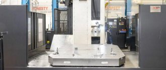
2А622Ф4 Horizontal boring machine with CNC. Purpose, scope
2A622F4 CNC horizontal boring machine is designed to perform a variety of boring, milling and drilling work, including contour milling and tapping.
Roughness of the machined surface of the hole during fine boring with a VK8 cutter installed in a retractable spindle, in SCh15 cast iron, GOST 1412-79; Ra=1.6 µm.
2A622F4 horizontal boring machine is designed in a configuration with a fixed stand carrying a vertically movable spindle head with a retractable spindle and a built-in rotary table with longitudinal and transverse (relative to the spindle axis) movement. Separate feed drives allow simultaneous processing along three coordinates and select the most optimal cutting mode, as well as change the feed rate of units during the cutting process.
The moving units are moved using ball screws with preload.
Lubrication of the moving guides and the main drive is automated.
2A622F4 machine into an automatic line. Degree of automation - F4 (control in loop mode).
2A622F4 machine is controlled by a numerical control device (CNC). Programmable movements along four axes - X, Y, Z, W. Axis B operates in positioning mode.
There is no loading device and device for transporting chips.
The coolant system consists of a pumping station with a capacity of 200 liters, a device for watering tools and parts, and a coolant collection system.
2A622F4 machine has a convenient auxiliary manual control system from a remote control.
The processing area is illuminated by a fluorescent lamp built into the spindle head.
There are no harmful secretions.
Compared to previous versions of the machine model 2A622F4, version 04 has the following advantages:
- the latest domestic CNC system of the CNC 2C42-65 class was used with a remote control, increased display sizes, and an increased memory capacity of up to 96K, including the volume of non-volatile memory (ROM) of 48K;
- all relay automation of the machine is recorded in the CNC ROM, which made it possible to eliminate a large number of relay contact equipment on the machine and thereby increase the reliability and durability of electrical equipment;
- the mode of recording a control program while processing a part in manual mode (machine self-learning) eliminated the stage of preliminary preparation of the program and its testing on the machine;
- in the program control mode there are additional automatic cycles for milling holes and processing mounting holes for the flange, which simplifies and shortens the process of the control program;
- a fault finding diagnostic system with display of the causes of faults on the display increases the maintainability of the machine and sharply reduces the troubleshooting time;
- The CNC device allows you to store programs both on punched paper tape and on the magnetic tape of a cassette recorder, which makes it easy to record, re-record and store programs;
- The presence of a movable control panel with a display, on which the data necessary for operation is displayed, ensures convenient control of the machine.
Design and operational features of the 2A622F4 machine:
- The rotating work table automatically stops at 0, 90, 180, 270 degrees and has high-precision feedback sensors in all coordinates
- Telescopic protection and automated lubrication of guides
- High-speed automatic hydraulic clamps
- Preloaded ball screws
- Powered tool clamping
- The spindle assembly is mounted on precision rolling bearings
- The spindle head with a retractable spindle is movable in the vertical direction
The machine meets the high requirements of the modern technical level of machine tool industry.
Noise characteristics in accordance with OST2 N89-40—75.
Vibration level in accordance with GOST 12.2.009-80.
Transportation of the machine must be carried out: for intra-Union deliveries in containers in accordance with GOST 10198-78.
Packaging category - KU-2 according to GOST 23170-78E and OST2 M92-1-81.
Temporary anti-corrosion protection (preservation) is carried out in accordance with GOST 9.014-78 and OST2 N89-30-79.
The choice of transport packaging and transportation conditions is carried out in accordance with GOST 7599-82 and OST N92-1-81.
Developer: Leningrad OKBS.
Machine accuracy class N according to GOST 8-82E.
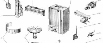
Description of the main components of horizontal boring machines 2A622
bed
The frame with four guides has a closed box-shaped section with walls reinforced by a system of longitudinal and transverse stiffeners. Three rows of shoes allow you to quickly and easily align the bed guides with the required accuracy.
When making machines with an increased transverse table travel, two additional side guides mounted on shoes are located on both sides of the main bed (Fig. 13).
The bed has wide flat ground guides with telescopic protection, ensuring long-term preservation of the original accuracy.
At the end of the frame there is a gearbox with an electric motor that drives the movement of the spindle headstock, spindle, radial support and table longitudinally.
The distribution of movements is carried out by means of electromagnetic couplings.
Front pillar
The front post, which carries the spindle head, is rigidly fixed to the plane of the frame and has high rigidity and vibration resistance.
Front guide posts - flat, polished; The side guides are hardened overhead steel strips along which the spindle head moves on rolling rollers.
Headstock
The spindle headstock is a unit consisting of interconnected mechanisms mounted inside and outside the headstock body: the drive of the main movement mechanism, the spindle device, the mechanisms for moving the spindle headstock, the boring spindle, the radial support of the faceplate (for machines 2A620-1, 2A620F1-1 and 2А620Ф2-1), tail section, control mechanisms and counting of movements of the boring spindle and radial support of the faceplate.
The drive of the main movement mechanism of the spindle head is carried out from a flanged single-speed three-phase electric motor using a spring coupling of variable stiffness through an intermediate gearbox with two electromagnetic couplings located on the side wall of the spindle head body.
The spindle device consists of a boring and hollow milling spindle.
boring spindle moves inside heat-treated bushings pressed into the milling spindle.
The milling spindle is mounted in precision cylindrical and tapered roller bearings.
The front end of the milling spindle is equipped with a flange having a cylindrical seating surface, an end keyway and threaded holes for securing tools and fixtures.
The faceplate with radial support is mounted on its own spindle.
The moving mechanisms of the spindle head, spindle and radial support are kinematically connected to a DC electric motor through a gearbox located at the right end of the frame and a vertical shaft.
All moving parts are supplied by DC electric motors with a wide range of drives.
The feed rate variator for the moving parts is located on the spindle head next to the speed switching mechanism and is a two-row multi-stage switch with a feed rate scale in millimeters per revolution. The amount of feed of the movable element can be changed during the cutting process. When changing the spindle speed, the feed rate in millimeters per revolution is automatically maintained constant when the feed rate in millimeters per minute actually changes.
Table
The rotary table of the machine has longitudinal and transverse movement and is centered in a support with a precision cylinder-roller bearing.
When making machines with an increased transverse table travel of 1600 mm, detachable side supports are installed on the lower table slides, moving along two additional side guides,
The side guides of the lower table slide are hardened steel bars along which the upper table slide moves on rollers.
The longitudinal movement of the table is carried out by a DC electric motor through a gearbox located at the right end of the frame. Transverse movement and rotation of the table—from a DC electric motor through a gearbox located at the rear end of the lower slide. The distribution of movement is carried out by electromagnetic couplings.
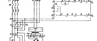
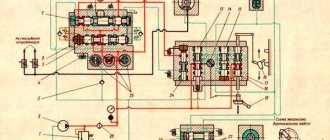
Kinematic diagram of horizontal boring machine 2A622
Kinematic diagram of horizontal boring machine 2a622
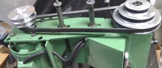
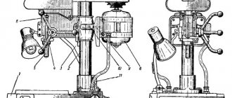
Drive of the main movement of horizontal boring machines 2A622
The spindle and faceplate rotation is driven by a two-stage speed unit with electromagnetic clutches mounted on the spindle head. Kinematic diagrams of the machines are shown in Fig. 14, 15 and in table. 2.
To protect against dynamic impact, the main drive mechanism has an elastic coupling (Fig. 16).
The transmission of motion to the spindle is carried out by two pairs of gears 63, 64 (100) and 65, 66 (69) (Fig. 17, 18, 19). The larger wheel 64 (100) rotates the spindle in the lower speed range with high torques, and the other, smaller wheel 66 (99) rotates the spindle in the upper speed range with lower torques. The movement is transmitted to the faceplate by a pair of wheels 36, 35. To turn on the rotation of the faceplate, there is a special handle.
Drive for spindle feed, radial support, faceplate, spindle headstock and longitudinal movement of the table
The axial movement of the spindle, the radial movement of the faceplate support (Fig. 20), the vertical movement of the spindle head and the longitudinal movement of the table are carried out from a common DC electric motor through a gearbox, which is located on the machine bed (Fig. 21).
The distribution of movement in the movement chain of the spindle, spindle head, radial support and table is carried out longitudinally by means of electromagnetic couplings.
The kinematic chain of the radial caliper drive has a planetary mechanism with satellites 26 and 71, which allows the caliper to move during rotation of the faceplate (Fig. 22).
Axial movement of the boring spindle is carried out by ball screws 86 and 84, located in the tail part of the spindle head (Fig. 23).
Vertical movement of the spindle head is carried out by means of a rotating nut located in the gearbox on the spindle head and a stationary ball screw mounted on the stand (Fig. 24).
The machines are equipped with a mechanism to prevent the spindle head from falling when the counterweight cable breaks (Fig. 25).
When the spindle head counterweight is suspended, part 243, connected to the counterweight cable, is in the upper position, compressing the package of disc springs 244. In this case, ball 245, resting against the shoulder of part 243, through a system of levers fixes part 248 mounted in the spindle head gearbox in the upper position.
If the counterweight cable breaks, part 243, under the influence of a package of disc springs 244, will move down, releasing ball 245 and part 248 through the lever system. Part 248, under the influence of spring 249, will move to the lower position and engage with part 247, which secures shaft 246 from rotation. At the same time, the spindle head is securely fixed from falling.
Drive for lateral movement and rotation of the table
Transverse movement of the table and rotation of the table are carried out from a common DC electric motor through a gearbox, which is located at the rear end of the lower sled.
The distribution of movement to the chain of transverse movement and rotation of the table is carried out by means of electromagnetic couplings in the gearbox (Fig. 26).
Kinematics of thread cutting
The machine allows you to cut metric and inch threads (see “Table of replacement gears for thread cutting”).
Thread cutting is carried out by a retractable spindle during its axial movement or by a radial support of the faceplate during longitudinal movement of the table.
For thread cutting, the spindle feed chain is connected to the spindle rotation drive via a guitar with a set of replaceable gears located at the front end of the spindle head.
To cut left-hand threads on the guitar, an idler gear is installed.
To move the faceplate support away from the steering wheel when cutting threads using the table feed, turn on the handle located on the spindle head cover.
Kinematics of the helm
The spindle head has a steering device for manual movement of the spindle, radial support, spindle head and longitudinal movement of the table.
The turret allows for fine movement of the moving body and rapid movement of the retractable spindle.
The steering wheel is turned on using a button from the remote control on the spindle head.
Machine 2A622F1 – how to buy, payment, delivery, warranty
The price for the horizontal boring machine 2A622F1 is indicated on our website including VAT for the standard delivery set.
It’s easy to buy a 2A622F1 machine - just call the numbers below in your city.
The sale of a horizontal boring machine for metal 2A622F1 is made with 100% prepayment if the equipment is in stock and 50% prepayment when the machine is put into production and payment of the remaining 50% after notification of its readiness for shipment. A different percentage ratio and a different payment procedure may be agreed upon with a specialist from the sales department of our company and specified in the Supply Agreement. Delivery of equipment is carried out by road and rail transport of carrier companies LLC "Business Lines", LLC "PEK", "Baikal-Service", LLC "Zheldorekspeditsiya" and other third-party carriers through transport and logistics companies, as well as by the transport of the Buyer or our company. The costs of transporting the goods are paid by the Buyer, unless otherwise agreed and specified in the Delivery Agreement. The warranty for the new horizontal boring machine 2A622F1 is 12 months. The manufacturer reserves the right to change the standard configuration and place of production of the equipment without notice!
Read also: Which miter saw blade is better
Please note that the prices indicated on our website are not a public offer, and please check the cost of the equipment with our sales managers!
If you need to buy a Horizontal boring machine with digital display 2A622F1, call:
in Moscow in St. Petersburg in Minsk +375 (17) 246-40-09 in Ekaterinburg in Novosibirsk in Chelyabinsk in Tyumen +7 (3452) 514-886
in Nizhny Novgorod in Samara in Perm in Rostov-on-Don in Voronezh in Krasnoyarsk
in Nur-Sultan;
in Abakan, Almetyevsk, Arkhangelsk, Astrakhan, Barnaul, Belgorod, Blagoveshchensk, Bryansk, Vladivostok, Vladimir, Volgograd, Vologda, Ivanovo, Izhevsk, Irkutsk, Yoshkar-Ola, Kazan, Kaluga, Kemerovo, Kirov, Krasnodar, Krasnoyarsk, Kurgan, Kursk , Kyzyl, Lipetsk, Magadan, Magnitogorsk, Maikop, Murmansk, Naberezhnye Chelny, Nizhnekamsk, Veliky Novgorod, Novokuznetsk, Novorossiysk, Novy Urengoy, Norilsk, Omsk, Orel, Orenburg, Penza, Perm, Petrozavodsk, Pskov, Ryazan, Saransk, Saratov, Sevastopol, Simferopol, Smolensk, Syktyvkar, Tambov, Tver, Tomsk, Tula, Ulan-Ude, Ulyanovsk, Ufa, Khabarovsk, Cheboksary, Chita, Elista, Yakutsk, Yaroslavl and other cities
Toll-free number throughout Russia.
In the CIS countries - Belarus, Kazakhstan, Turkmenistan, Uzbekistan, Ukraine, Tajikistan, Moldova, Azerbaijan, Kyrgyzstan, Armenia in the cities of Nur-Sultan, Bishkek, Baku, Yerevan, Minsk, Ashgabat, Chisinau, Dushanbe, Tashkent, Kiev and others for purchase equipment such as Horizontal boring machine with digital display 2A622F1, call any convenient number listed on our website, or leave your contacts under the ORDER A CALL button at the top of the site - we will call you back.
Technical characteristics of horizontal boring machines 2A622
| Parameter name | 2A620 | 2A622 |
| Basic machine parameters | ||
| Diameter of retractable boring spindle, mm | 90 | 110 |
| Largest diameter of spindle boring, mm | 240 | 320 |
| The largest diameter of bore by the faceplate support, mm | — | |
| Maximum length of boring and turning of the faceplate with a caliper, mm | — | |
| Coordinate setting accuracy, mm | 0,025 | 0,025 |
| Accuracy of rotary table installation, sec | 3 | 3 |
| The largest diameter of the drill (along the cone), mm | ||
| Table | ||
| Working surface of the table, mm | 1120 x 1250 | 1120 x 1250 |
| Maximum mass of the processed product, kg | 4000 | 4000 |
| Maximum table movement, mm | 1000 x 1250 | 1000 x 1250 |
| Limits of table working feeds (lengthwise and crosswise), mm/min | 1,25…1250 | 1,25…1250 |
| Maximum table feed gain (lengthwise and crosswise), kgf | 2000 | 2000 |
| Dial scale division, mm | 0,025 | |
| Table rotation dial scale division, degrees | 0,5 | 1 |
| Switching stops | There is | There is |
| Speed of fast longitudinal movements, m/min | 6,0 | 6,0 |
| Speed of fast transverse movements, m/min | 5,0 | 5,0 |
| Speed of fast installation circular movements, rpm | 2,8 | |
| Spindle | ||
| Maximum horizontal (axial) movement of the spindle, mm | 710 | 710 |
| Spindle speed, rpm | 10…1600 | 10…1250 |
| Number of spindle speeds | 23 | 22 |
| Limits of spindle working feeds, mm/min | 2…2000 | 2…2000 |
| Limits of working feeds of the radial caliper, mm/min | 0,8…800 | — |
| Limits of spindle head working feeds, mm/min | 1,4…1110 | 1,4…1110 |
| Maximum vertical movement of the spindle head (installation), mm | 1000 | 1000 |
| Speed of rapid movements of the spindle head, m/min | 6,0 | 6,0 |
| Speed of rapid spindle movements, m/min | 4,0 | 4,0 |
| Faceplate rotation speed, rpm | 6,3…160 | — |
| Number of faceplate speeds | 13 | 13 |
| Ability to disable faceplate rotation | There is | There is |
| Possibility of simultaneous feed of support and spindle | There is | There is |
| Maximum movement of the radial support of the faceplate, mm | 160 | — |
| Speed of rapid movements of the radial support, m/min | 1,39 | — |
| Maximum torque on the spindle, kgf*m | 140 | 180 |
| Maximum torque on the faceplate, kgf*m | 250 | — |
| Maximum spindle feed gain, kgf | ||
| Maximum caliper feed gain, kgf | ||
| Maximum headstock feed gain, kgf | ||
| Cutable metric thread, mm | 1…10 | 1…10 |
| Cutable inch thread, number of threads per 1″ | 4…20 | 4…20 |
| Drive unit | ||
| Digital display device (DRO) | F5147 | F5147 |
| Program control device (CNC) | 2P62-3I | 2P62-3I |
| Number of electric motors on the machine | ||
| Main motion drive electric motor Power, kW | 11 | 11 |
| Electric motor for driving the longitudinal feed of the table and spindle, kW | 3,8 | 3,8 |
| Electric motor for driving cross feed and table rotation, kW | 3,8 | 3,8 |
| Total power of electric motors, kW | 25 | 25 |
| Dimensions and weight of the machine | ||
| Dimensions of the machine, including travel of the table and slide, mm | 6070 x 3970 x 3220 | 6070 x 3970 x 3220 |
| Machine weight, kg | 18300 | 17800 |
- Horizontal boring machines 2A622-1, 2A620-1, 2A622F2-1, 2A620F2-1, 2A622F1-1, 2A620F1-1, 2A622PF1-1. Operating manual 2A622-1.000.000 RE, 1976
- Bernstein-Kogan V.S. Electrical equipment of jig boring and thread grinding machines, 1969
- Glukhov N.M. Working on jig boring machines, 1953
- Grigoriev S.P., Grigoriev V.S. Practice of coordinate boring and milling work, 1980
- Ipatov S.S. Jig boring machines in precision instrumentation, 1954
- Kashepava M.Ya. Modern jig boring machines, 1961
- Kudryashov A.A. Tool production machines, 1968
- Smirnov V.K. Turner-borer. Textbook for technical schools, 1982
- Tepinkichiev V.K. Metal cutting machines, 1973
- Zazersky E.I., Gutner N.G. Turner-borer, 1960
- Ponomarev V.F. Handbook of a lathe-borer, 1969
- Smirnov V.K. Turner-borer. Textbook for technical schools, 1982
- Bogdanov A.V. Boring business, 1960
Bibliography:
Related Links. Additional Information
- Repair of hydraulic systems of metal-cutting machines
- Designations of hydraulic circuits of metal-cutting machines
- Repair of gear hydraulic pumps
- Adjustment of milling machines
- Milling machine repair technology
- Adjustment of screw-cutting lathe 1K62
- Designations of kinematic diagrams of metal-cutting machines
- Methodology for checking and testing screw-cutting lathes for accuracy
- Methodology for checking and testing vertical drilling machines for accuracy and rigidity
Home About the company News Articles Price list Contacts Reference information Interesting video KPO woodworking machines Manufacturers
2А622Ф4 – Horizontal boring and milling machine
Buy machine bearing with delivery
Specifications:
Machines model 2a622f4 are designed for milling planes, grooves, ledges; drilling, reaming, centering and countersinking holes; boring and reaming holes; thread cutting with taps; surface turning, circumferential grooving and end trimming
Accuracy class – according to GOST 8-82 Main dimensions – GOST 7058
Dimensions of the working surface of the rotary table according to GOST 6569-75, mm:
Width – 1250-1 Length – 1250-1
Distance between grooves – 160 +-0.5 Number of grooves – 7 Width of table groove according to GOST 1574-75, mm – 22+0052 End of retractable spindle according to GOST – 24644-81 With degree of cone accuracy according to GOST 19860-74 – 50ATS Diameter D retractable spindle - 110 (for 2V622F4 - 125) Maximum mass of the workpiece, kg - 4000 Maximum longitudinal movement of the retractable spindle, mm - 710 Maximum longitudinal movement of the rotary table, mm - 1000 Maximum vertical movement of the spindle head, mm - 1000 Maximum transverse movement of the rotary table , mm – 1250 Spindle rotation speed, min-1 – 6…2500 (4-1250 when machine version is 03) Discreteness of setting rotation speeds according to the program, min-1 – 1 Maximum permissible torque on the retractable spindle – 1765 (180)
Maximum axial force, N(kgf)
When feeding with a retractable spindle – 10780 (1100) When feeding by a table – 19600 (2000)
The greatest tangential cutting force when boring with a single-ended cutter fixed in a retractable spindle, with a distance from the end of the milling spindle to the top of the cutter no more than 200 mm, N (kgf) – 7840 (800) Largest drill diameter, mm – 50 Largest cutter diameter, mm – 250 Feed of the retractable spindle, table headstock in the transverse and longitudinal directions, mm/min – 1-5000 Speed of fast installation movements of the moving units, mm/min – 10000
Machine dimensions, mm
Width – 4130 Length – 6335 Height – 3980
Weight of the machine without hydraulic and electrical equipment installed outside the machine – 17500 Weight of the machine, kg – 20500 Number of simultaneously controlled coordinates – 4/5 Technical characteristics of electrical equipment. Type of current supplying the network - alternating, three-phase Current frequency, Hz - 50+-0.1 Voltage, V - 380+-5% Type of current of auxiliary electric drives - alternating, three-phase Voltage of the working area lighting circuit, V - 110 Voltage of the electromagnets of the distribution spools – 24, constant Power of the main movement electric motor, kW, not less than – 25 Rated torque of the feed electric motor, not less than N*m (kgf*m) – 47(4.8) Rated total power consumption at full load of simultaneously operating electric motors, kW – 69.4 Technical characteristics of hydraulic equipment. Pressure in the hydraulic system, MPa (kgf/cm2) no more than – 4.9+-02(50+-2) Pressure in the lubrication system, MPa (kgf/cm2) no more than – 0.98(10) Pump capacity, l /min – 5/18 Oil brand – IGP-18 TU38,101798-7 purity class 12 – according to GOST 17216-71 Cooling capacity of the refrigeration machine, not less, kcal/h – 400
Read also: How to add oil to a rolling jack video