Information about the manufacturer of the broaching machine 7B56
The developer and manufacturer of the 7B56 horizontal broaching machine is the Minsk Machine Tool Plant named after S.M. Kirov , founded in 1881.
Machine tools produced by the Minsk Machine Tool Plant named after S.M. Kirov
- 7A510
- horizontal broaching machine 100 kN - 7A534
- horizontal broaching machine 250 kN - 7B55
- horizontal broaching machine 100 kN - 7B56
- horizontal broaching machine 200 kN - 8В66
- automatic circular saw cutting machine Ø 280 - 8B66A
- automatic circular saw cutting machine Ø 280 - 8G662
- automatic circular saw cutting machine Ø 280 - 8G663
- automatic circular saw cutting machine Ø 285 - 7523
— horizontal broaching machine 100 kN - 7534
— horizontal broaching machine 250 kN - MP8-876
– combined household woodworking machine - MP8-1540
– combined household woodworking machine
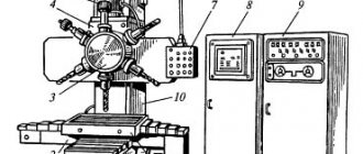
Horizontal broaching machines for internal broaching. Machine 7B510
The domestic machine tool industry produces horizontal broaching machines with the highest traction force of 25-980 kN, with the maximum carriage stroke of 1-2 m. In Fig. 52 shows the 7B510 machine. It is designed for pulling through holes. Using special devices, the machine can also process external surfaces.
Nominal traction force 100 kn; the lowest and highest speeds of the working stroke are 1.5-9 m/min, the reverse stroke is 25 m/min, the supply and removal of the broach is 15 m/min; power of the electric motor of the piston pump is 17 kW. When the machine is equipped with an automatic loading and unloading system, it can operate with an automatic cycle.
Rice. 52. Horizontal broaching machine 7B510
Design
In the hollow part of the welded box-shaped frame 1, the main units of the hydraulic drive, which is the main one for this type of machine, are mounted. On the left is power cylinder 2. The piston rod is connected to the working slide, which, moving in guides along the axis of the machine, serves as additional support. At the end of the rod there is a sleeve with a chuck for securing the left end of the broach 3, and its right end is clamped in the auxiliary chuck 4. The device for installing the part and the part itself rests against the stationary body of the frame 5.
The right part of the frame is attached and is used for mounting units for automatic supply and removal of the broach. The necessary movements are carried out by an auxiliary power cylinder mounted on the right side of the machine. This happens as follows. During the working stroke to the left, the auxiliary chuck 4 slides accompany the broach until they touch the hard stop. In this case, the connection between the broach and the chuck is broken using a spring-loaded cam. After this, a working stroke occurs, carried out by power cylinder 2. During the reverse stroke, the rear shank of the broach again enters the auxiliary chuck and pushes it to the right to its original position.
The machine operates with a full and simple cycle. With a full forward stroke cycle, the broach is supplied, the working stroke is slow, the adjusted working stroke is a slow working stroke when the calibrating teeth and stops are working. During reverse stroke: slow motion and retraction of the broach. A simple cycle differs from a complete cycle by the absence of feed in and out of the broach.
Hydraulic diagram
The basic hydraulic diagram of the machine is shown in Fig. 53. A high-pressure piston pump 30 type NP4M is shown conventionally in the figure. Pipeline 28 is connected to the suction cavity, and pipeline 29 is connected to the discharge cavity. The pump ensures the operation of the machine, carrying out the working and return strokes of the working slide using a hydraulic cylinder 19. The auxiliary hydraulic drive consists of a gear pump 1 built into the piston pump housing, and an auxiliary hydraulic cylinder 12 for supplying and removing the broach.
Rice. 53. Hydraulic diagram of the machine 7B510
Oil from pump 1 is supplied to the support cylinder 31, to the central spool 33 and to the control mechanism, in which there are four pilot spools controlled by solenoids 24, 25, 26 and 27. The central spool 33, together with a disk 35 attached to its end, under by the action of the spring 34 is pressed to the left. The disk 35 has five holes for the passage of screws 37, which regulate the performance of the pump 30 (stator displacement). When pressure is applied under the piston 36, it will rest against the adjusting screw 37 with its rod and limit the advancement of the disk 35 with the central spool 33, which is connected to the piston 32 of the cylinder.
Let's consider the operation of the hydraulic circuit for a full cycle. In the initial position, the working slide is in the extreme right position, the broach is in the retracted position. By pressing the “Start” button on the control panel, the pumps are turned on. In this case, all four electromagnets (24, 25, 26 and 27) are turned off, and the piston pump 30 does not pump oil, since the rotor and stator are concentric.
Broach supply
The broach is supplied by pressing the control button on the remote control. In this case, electromagnet 9 is turned on. Auxiliary spool 7 moves to the left and connects pipelines 3 and 8. Oil from gear pump 1 through pipeline 2, through a bore in the spool body, pipeline 3-8 enters under the right end of the main spool 4 and moves it to the far left position, connecting pipelines 2 and 6. Oil enters the rodless cavity of the auxiliary cylinder and moves the broach. At the end of the broach supply, the limit switch 13 is triggered, which turns off the electromagnet 9 and turns on the electromagnet 27. As a result, the oil goes under the piston 36 and shifts the pump stator to the left to the position adjusted by screw 37 (as shown in the diagram). At the same time, the left end of the broach with its shank enters the automatic cartridge mounted on the right end of the piston rod of working cylinder 19.
Slow working speed
As a result of the above movement, cavity I becomes discharge, cavity II becomes suction. Oil through pipeline 29 enters under the right end of the differential spool 23 and moves it to the left until it stops. Pipeline 29 communicates with pipeline 21, and oil enters the rod cavity of working cylinder 19 and moves it to the left until it stops. The oil displaced from the rodless cavity enters the suction cavity of the piston pump 30 through pipelines 20-28. Excess oil, caused by the difference in the areas of the rod and rodless cavities, is drained through spool 22, which maintains a constant pressure in the cavity of the working cylinder.
Fast working stroke
A fast working stroke is carried out when the cam is pressed on the limit switch 17. This turns on the electromagnet 25. The stator of the pump 32 further shifts to the left, increasing the productivity of the pump and the speed of movement of the working slide. At the end of the working stroke, when the first calibrating teeth of the broach enter the workpiece, the cam presses the limit switch 16, which turns off the electromagnet 25. A slow working stroke begins as a result of a decrease in pump performance, as the eccentricity of the pump block decreases. At the end of the working stroke, the limit switch 15 is activated and turns off the electromagnet 27 - a stop occurs.
Reverse
The reverse stroke occurs when electromagnet 26 is turned on. The piston pump block moves to the left, line 28 becomes discharge, and line 29 becomes suction. Oil through pipeline 28 enters under the left end of the differential spool 23 and moves it to the extreme right position. Pipeline 28 is connected to pipelines 20-21 and both cavities of the working cylinder 19 communicate in this way with the pump discharge line. Due to the unequal areas under pressure, the piston moves to the right. With further movement of the working slide, the cam presses the limit switch 17, which turns on the electromagnet 24. At the same time, slow motion begins due to a decrease in pump performance. At the end of the return stroke, the travel switch 18 is triggered, turning off the electromagnets 26 and 24. The slide stops, the left end of the broach is automatically released and the right end is clamped in the chuck 4 (see Fig. 52), located near the housing 5.
7B56 Horizontal broaching machine for internal broaching. Purpose and scope
The horizontal broaching machine 7B56 has been produced since 1981. The machine has been discontinued. Currently, the plant produces more advanced horizontal broaching machines and semi-automatic machines: 7A523, 7A534, 7A545, 7555.
7B56 horizontal broaching machine is designed for processing, by broaching, pre-processed or rough through holes of various geometric shapes and sizes of parts made of ferrous and non-ferrous metals and alloys. Using special devices, you can process external surfaces.
7B56 broaching machine is distinguished by high productivity and high processing accuracy.
The most effective use of the 7B56 is in mass and large-scale production. The ease of readjustment of the machine allows it to be used in small-scale and individual production.
By agreement with the customer, the machine is supplied both in a universal version and with special fixtures and tools for processing one or more specific parts.
Design features of the horizontal broaching machine 7B56:
- Hydraulic drive
- Stepless speed control of working and reverse strokes
- Mechanized feed in and out of the broach over the entire cutting length
- Increased rigidity and vibration resistance, allowing operation over the entire range of operating speeds and traction forces, while maintaining good surface finish and high durability of the cutting tool
- Centralized forced lubrication of rubbing surfaces
- Hydraulic oil filtration
- Signaling using an electric contact pressure gauge about the dullness of the cutting tool
- Placing the starting and safety electrical equipment on a rotating panel in a separate electrical cabinet facilitates its maintenance and increases its service life
- High reliability of electrical equipment due to the use of contactless track switches, low-current electrical control equipment and DC electromagnets
- Possibility of integrating the machine into an automatic line
The machine is certified according to the first quality category.
The roughness of the treated surfaces is Rz20—Ra 0.63 microns.
Machine accuracy class N according to GOST 8-77.
The corrected sound power level LpA does not exceed 108 dBA.
Design organization - Minsk Special Design Moscow Bureau of Broaching Machines.
Main technical characteristics of the horizontal broaching machine 7B56
- Nominal traction force - 200 kN (20 tf)
- The longest working stroke of the slide is 1600 mm
- The diameter of the hole in the faceplate is 130 mm
- Working speed - 1.5 ÷ 11.5 m/min
- Power of the electric motor of the main movement drive is 30 kW
- Machine weight - 5.2 t
Review of the metalworking machine model 7B56
Since 1981, a broaching machine model 7B56 began to be produced for the industrial area. They are processed on a broaching machine of this model using the method of correct horizontal broaching through the through holes of the part. The processing itself is rough, and the composition of the processed parts is ferrous and non-ferrous metals, as well as various alloys.
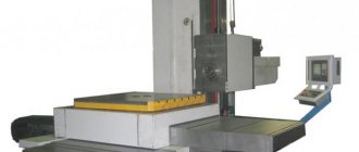
Appearance of the machine 7B56
Broaching machine 7B56
If additional tools were used, it became possible to carry out external processing of parts. This device had high processing accuracy and sufficiently high productivity to be used on an industrial scale. Below is a description of the design features and characteristics of the broaching horizontal machine 7B56.
Its features include:
- smooth adjustment of the speed of both working and return movement;
- hydraulic drive of the existing broaching mechanism;
- good quality of the machined surface, associated with increased resistance of the machine to vibrations. This condition was achieved due to an increased level of rigidity and allows for uniform operation over the entire range of traction forces at any speed;
- automatic supply of lubricant to all rubbing surfaces, as well as high-quality filtration of oil in the hydraulic system;
- triggering of the existing alarm when the cutting tool becomes dull;
- the presence of contactless track switches, as well as DC electromagnets, makes it possible to achieve a high degree of reliability and safety of all electrical equipment;
- the possibility of upgrading this machine for subsequent installation on an automatic line;
- the processing accuracy of the horizontal broaching machine 7B56 belongs to the normal class (H);
- the total length of the working stroke of the existing horizontal slide is 160 cm;
- the speed of movement of the broaching mechanism varies in the range of 1.5 – 11.5 meters per minute;
- hydraulic traction force is 200 kN;
- the presence of a powerful 30 kilowatt electric motor that drives the main drive.
Hydraulic diagram of broaching machine 7B56
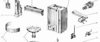
7B56 Location of components of a broaching machine
Photo of horizontal broaching machine 7B56
7B56 main components of a broaching machine
- electrical equipment
- slave cylinder
- work skids
- Remote Control
- cooling device
- support roller
- auxiliary cartridge
- auxiliary skid
- side stand
- locking and unlocking mechanism
- auxiliary cylinder
- working chuck
- work skids
- mechanism for regulating the movement of the machine
- coolant tank
- pumping unit
The main frame is used to accommodate the main parts of the machine: the working cylinder and the working slide, the alignment of which is ensured by bed strips welded inside the frame along its entire length. In the front part of the frame, the frame is closed by a massive base plate, in which a precise hole is made, strictly coaxial with the working cylinder of the machine. This hole is used to install the machine support plate. A slide is provided near the base plate, through which chips with coolant fall into a receiving box located next to the coolant tank. At the front of the main frame, there is a support roller mechanism at the bottom. Its purpose is to support the broach as its rear shank exits the auxiliary chuck. Support is provided until the end of the return stroke of the working slide, when the rear broach shank again enters the auxiliary chuck. The mechanism provides regulation using a spring device for working with broaches of different diameters.
The working slide connects the working cylinder rod with the working chuck. To install the working chuck, they are provided with an adapter sleeve with a conical mounting hole. The design of the working slide allows the load to be transferred directly from the hydraulic cylinder rod to the working chuck using a special coupling and coupler (Fig. 68). The working slides of manufactured horizontal broaching machines move along one flat and one V-shaped bed guide, which increases the geometric accuracy of the machine. The slides are equipped with screwed guide bars that allow compensation for wear in the guides. There is a follower at the bottom of the slide to lower the support roller in the main bed when the work slide approaches the base plate.
The mechanism for regulating the movement of the machine is mounted in the upper part of the main frame. It is made in the form of two rollers, the angular rotation of which turns on and off the limit switches that control the operation of the machine’s hydraulic system. These switches are located outside the main frame in a special housing. By adjusting the position of the cams attached to the rollers, the required values of the working and slow strokes are ensured, as well as the value of the slow stroke and the extreme position of the working slide at the end of the return stroke. The rotation of the cams occurs under the influence of a copier mounted on the working slide.
The attached frame is designed for mounting mechanisms that provide supply and removal of broach. The inlet and outlet movements are communicated simultaneously to the support roller 6 (see Fig. 67) and the auxiliary slide 8 from the auxiliary cylinder 11. At the end of the broach supply, when the support roller is lowered into the opening of the attached frame, the locking and unlocking mechanism 10 ensures the release of the auxiliary slide from the mechanism inlet and outlet. This allows the auxiliary slide to accompany the broach until the end of the cut, which becomes possible due to the fact that the support roller 6 is recessed. At the end of the return stroke, the auxiliary slides are again rigidly connected to the inlet and outlet mechanism using a locking and unlocking mechanism. After this, the withdrawal of the broach begins, at the beginning of which the supporting roller rises and becomes the support of the broach. Its rear shank is fixed in an auxiliary chuck.
When broaching with assisted broaching, the machine mod. 7B56 operates in full half-cycle mode. The interaction of the considered machine mechanisms is reflected in Table. 21. When working in a simple half-cycle mode, the mechanisms located in the attached frame are excluded from operation. The sequence of actions is completely preserved. The simple half-cycle mode is usually used when working with small broaches, for example, keyway ones.
The adjustment dimensions that determine the capabilities of the machine in terms of the broaching length and the length at which tool tracking is provided are shown in Fig. 68.
7B55 Arrangement of components of a horizontal broaching machine
Location of components of the broaching machine 7B55
7B55 main components of a broaching machine
- main (working) hydraulic cylinder
- electrical cabinet
- main hydraulic drive electric motor
- hydraulic tank
- auxiliary hydraulic drive motor
- main bed
- Remote Control
- base plate
- faceplate
- support roller
- auxiliary cartridge
- auxiliary skid
- auxiliary (attached) bed
- auxiliary hydraulic cylinder
- working chuck
- work skids
- slider-rod
- slider stroke control mechanism
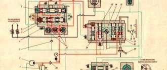
7B56 Hydraulic diagram of a horizontal broaching machine
Hydraulic diagram of the broaching horizontal machine 7B56 (Fig. 153)
The hydraulic drive (Fig. 153) carries out the working and auxiliary movements of the machine’s executive bodies in the working cycle.
The broach is supplied and discharged by an auxiliary hydraulic cylinder 31, which is powered by a vane pump 22 through a coarse and fine filter 24 and 25. In the initial position, the control valve 28 is in the middle position. Oil from the gear control pump 6 is supplied to both ends of the hydraulic distributor 26, which also keeps it in the middle position. In this case, the right part of the hydraulic cylinder 31 is isolated, and the left part is connected to the drain.
Pressing the “Start cycle” button turns on electromagnet E6. Distributor 28 switches to the left, connecting lines 12 and 29 to each other, and pipeline 27 with a drain; oil is supplied under the right end of hydraulic distributor 26, moving it to the left. Pipelines 30 and 32 are connected to each other and pump 22. The pressure in both cavities of cylinder 31 is the same, the area of the right, rodless cavity is larger than the left one - the piston moves to the left and the broach is drawn to the left cartridge. Oil from the left cavity of the cylinder flows into the right cavity, increasing the flow of pump 22.
Working cylinder 35 receives oil from radial piston reversible pump 1. During the working stroke, the pressure line is 13-33-34, and the drain line is 36-37-14. Some of the drained oil feeds the pump; the excess is discharged through valve box 7 and pressure spool 8. During the reverse stroke, oil from the pump flows through pipelines 14 and 36. Oil flowing from the cylinder cannot pass through check valve 33 and flows from the right to the left side of the cylinder through check valve 37. Oil is taken from the tank through check valve 5 and valve box 7.
In the initial position, both cavities of pump 1 are connected by pipeline 4 through overflow valve 2 in position B. This prevents spontaneous movement of the slide when the zero position of the pump is inaccurately adjusted. Before the slide moves, valve 2 is moved to position A and the pump cavities are disconnected. Depending on the direction (right - left) of the stator displacement relative to the rotor, the suction and discharge cavities of the pump change their purpose, and consequently, the speed of movement of the slide changes.
Various stator displacements are set during adjustment by adjusting screws 19, which serve as stops for the piston rods 21. The position of the disk 20 and the associated stator is determined by one piston 21. When the electromagnet 31 is turned on, switching the distributor 15, a working stroke occurs, which is accelerated when 32 is additionally turned on , causes a reverse motion, which slows down when the electromagnet 34 is turned on. The order and moment of switching the electromagnets depend on the arrangement of the limit switches. Safety valves 3 and 9, pressure spools 10, 11, 23 and 38 release part of the oil to drain when the pressure in certain lines rises to a value greater than the pressure at setting.
Hydraulic diagram of a broaching horizontal machine 7B56
Hydraulic diagram of the machine (Fig. 69). Two slanted arrows on the symbol of the working 1 and auxiliary 8 cylinders mean that they have adjustable braking (deceleration) at the end of the stroke when moving in both directions. All hydraulic units of the machine are mounted on tank 12 with a capacity of 1250 l. Thick lines in Fig. 69 shows the connection lines of suction, pressure and discharge. Control communication lines are shown as thin lines. Control communication lines 4-7 allow you to control the pressure at the key points of the hydraulic circuit. The pressure is controlled using pressure gauge 3, to which any of the listed control communication lines is connected in series through hydraulic remote control I. Line 4 allows you to control the pressure in the rod cavity of the working cylinder during the working stroke; line 5 - in the rodless cavity of the working cylinder during reverse stroke; line 6 - in the control lines for the operation of hydraulic units; line 7 - in the pressure line of the auxiliary cylinder. In addition to pressure gauge 5, the hydraulic circuit of the machine includes a control electric contact pressure gauge 2: This pressure gauge is adjusted to a pressure increased by approximately 30% compared to the pressure at the start of work with a new or sharpened tool. When the broach becomes blunt, the maximum pressure in the rod cavity will increase. When the pressure increase reaches 30%, which corresponds to the maximum permissible value of blunting, the electric contact pressure gauge turns on the signal light on the control panel 4 (see Fig. 67) of the machine. This is a signal to resharpen or change the broach in order to prevent tool breakage and prevent defects.
The auxiliary cylinder receives drive from vane pump 10 (see Fig. 69), which supplies oil under pressure through filter 11 to the reversible hydraulic control valve. Safety valve 9 allows you to maintain pressure at a given level.
Unit III of the radial piston pump includes, in addition to the pump itself, all the necessary control equipment that allows you to adjust the pump performance when switching from normal to slow speed and vice versa, change the direction of movement of the rod, and maintain the pressure in the cavities of the working cylinder at a given level.
Limit switches 1ПВ—6ПВ give commands to operate spool valves (distributors) in the motion control systems of the working and auxiliary cylinders. The machine can operate in full or simple half-cycle mode, as well as in adjustment mode. Cyclograms of the machine operation are shown in Fig. 70. The squares show the devices that are currently turned on.
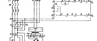
Schematic hydraulic diagram of the horizontal broaching machine 7B55
The high-pressure piston pump 30 type NP4M is shown in the figure conditionally. Pipeline 28 is connected to the suction cavity of the pump, and pipeline 29 is connected to the discharge cavity. The pump ensures the operation of the machine, carrying out the working and return strokes of the working slide using a hydraulic cylinder 19. The auxiliary hydraulic drive consists of a gear pump 1 built into the piston pump housing, and an auxiliary hydraulic cylinder 12 for supplying and removing the broach.
Oil from pump 1 is supplied to the support cylinder 31, to the central spool 33 and to the control mechanism, which contains four pilot spools that control solenoids 24-27. The central spool 33, together with the disk 35 attached to its end, is pressed to the left under the action of the spring 34. The disk has five holes for the passage of screws 37, which regulate the flow of the pump 30 (stator displacement). When there is pressure under the piston 36, it will rest against the adjusting screw 37 with its rod and limit the advancement of the disk 35 with the central spool 33, which is connected to the piston 32 of the cylinder.
Let's consider the operation of the hydraulic system for a full cycle. In the initial position, the working slide is in the extreme right position, the broach is in the retracted position. By pressing the “Start” button on the control panel, the pumps are turned on. In this case, all four electromagnets 24 - 27 are turned off, and the piston pump 30 does not supply oil, since the rotor and stator are concentric.
The broach is supplied by pressing the control button on the remote control. In this case, electromagnet 9 is turned on, auxiliary spool 7 moves to the left and connects pipelines 3 and 8. Oil from gear pump 1 through pipeline 2 through a bore in the spool body, pipelines 3 and 8 enters under the right end of the main spool 4 and moves it to the extreme left position , connecting pipelines 2 and b. Oil enters the rodless cavity of the auxiliary cylinder and moves the broach. At the end of the broach supply, the limit switch 13 is triggered, which turns off the electromagnet 9 and turns on the electromagnet 27. As a result, the oil goes under the piston 36 and shifts the pump stator to the left to the position adjusted by screw 37 (as shown in the diagram). At the same time, the left end of the broach with its shank enters the automatic cartridge mounted on the right end of the piston rod of working cylinder 19.
Slow working speed . As a result of the above movement, cavity 1 becomes discharge, cavity 11 becomes suction. Oil through pipeline 29 enters under the right end of the differential spool 25 and moves it to the left until it stops. Pipeline 29 communicates with pipeline 21, oil enters the rod cavity of working cylinder 19 and displaces it to the left until it stops. The oil displaced from the rodless cavity enters the suction cavity of the pump 50 through pipelines 20 and 28. Excess oil, caused by the difference in the volumes of the rod and rodless cavities, is drained through spool 22, which maintains constant pressure in the cavity of the working cylinder.
A fast working stroke is carried out when the cam is pressed on the limit switch 17. In this case, the electromagnet 25 is turned on, the stator of the pump 32 further shifts to the left, its flow and the speed of movement of the working slide increase. At the end of the working stroke, when the first calibrating teeth of the broach enter the workpiece, the cam presses the limit switch 16, which turns off the electromagnet 25. A slow working stroke begins as a result of a decrease in pump flow, as the eccentricity of the pump block decreases. At the end of the working stroke, the limit switch 15 is triggered and turns off the electromagnet 27 - a stop occurs.
The reverse stroke occurs when electromagnet 26 is turned on. The piston pump block moves to the left, line 28 becomes discharge, and line 29 becomes suction. Oil through pipeline 28 enters under the left end of the differential spool 23 and moves it to the extreme right position. Pipeline 28 is connected to pipelines 20 - 21, and both cavities of the working cylinder 19 communicate in this way with the pump discharge line. Due to the difference in areas under pressure, the piston moves to the right. With further movement of the working slide, the cam presses the limit switch 17, which turns on the electromagnet 24. In this case, a slow motion begins due to a decrease in the pump flow. At the end of the return stroke, the travel switch 18 is activated, turning off the electromagnets 26 and 24. The slide stops, the left end of the broach is automatically released and its right end is clamped in the chuck 4 (see Fig. 51), located near the housing 5.
The broach is retracted at the end of the slow return stroke. By pressing the cam on the limit switch 18 (Fig. 52), the electromagnet 10 is turned on. The spool, controlled by this magnet, occupies the 82 right position and connects pipelines 3 and 5. Oil from pump 1 through pipeline 2 through the bore in the spool body, pipelines 3 and 5, enters under the left end of spool 4 and moves it to the extreme right position, connecting pipelines 2 and 11. Through these pipelines, oil enters the rod cavity of auxiliary cylinder 12 and moves the broach. At the end of the broach retraction, the limit switch 14 is triggered, which turns off the electromagnet 10. The auxiliary chuck slide stops. After installing the next part for processing, the cycle is repeated.
A simple cycle differs from the one described in that the mechanism for supplying and removing the broach is not involved in the operation.
Cyclogram of operation of the 7B56 broaching machine in full and simple half-cycle modes
Cyclogram of operation of broaching machine 7B56
In the full half-cycle mode (see Fig. 70,a), the sequence of operation of the machine will be as follows. In the initial state, the working and auxiliary slides will be in the extreme right position. The initial position of the piston of the working hydraulic cylinder in Fig. 69 is shown with thin lines. The machine operating mode switch on control panel 4 (see Fig. 67) is set to the “Full half-cycle” position.
After pressing the control button (CU) “Cycle start”, the reversible spool directs oil from the vane pump 10 (see Fig. 69) into the rodless cavity of the auxiliary cylinder 8. The piston of the auxiliary cylinder moves to the left, a broach is supplied, at the end of which the 6PV limit switch is activated . This switch gives the command to turn on the hydraulic distributor, which directs oil from the radial piston pump to the rod end of the working cylinder. The work process begins. At the same time, the reversible hydraulic distributor turns off the oil supply to the auxiliary cylinder.
The ZPV limit switch is configured so that it is triggered at the moment the calibrating teeth of the broach enter the workpiece. At the same time, in the control system of the radial piston pump, a hydraulic distributor is activated, which reduces the pump’s performance, which leads to a decrease in cutting speed. The 1PV limit switch, triggered at the end of the working stroke, gives the command to stop the oil supply to the rod cavity of the working cylinder, and the machine stops.
To start the reverse movement, you must press the “Start cycle” button again. At the same time, the hydraulic distributor is turned on, directing oil from the radial piston pump into the rodless cavity of the working cylinder. During the reverse stroke, oil from the rod cavity through check valve 12 (see Fig. 69) will be forced out into the rodless cavity. Triggering of the 4PV limit switch gives a command to turn on the spool, which reduces the performance of the radial piston pump, which leads to a decrease in the reverse speed. The 2PV limit switch, which is triggered at the end of the reverse stroke, gives a command to stop the supply of oil to the working cylinder, and at the same time a command is given to supply oil to the rod end of the auxiliary cylinder. The broach retraction begins. The 5PV limit switch is triggered at the end of the broach outlet and gives the command to stop the oil supply to the auxiliary cylinder. The machine stops.
The simple half-cycle mode differs in that the mechanism for supplying and removing the broach is not involved in the operation. In setup mode, the machine’s hydraulic system allows you to independently control the movements of the working and auxiliary slides.
The speeds of the working and return strokes of the working slide are adjusted using four screws of the pump control mechanism. Speed adjustments should only be made in setup mode. Two screws are used to adjust the speed of the working stroke and the speed of the working slow stroke. The other two screws adjust the speed of reverse and reverse slow motion. The value of the working stroke speed is determined by the optimal tool life in relation to specific processing conditions. It is necessary to take into account that the speed of the working stroke is limited not only by the specified durability, but also by the cutting forces when pulling a specific part. The cutting forces during the broaching process can be judged by the pressure gauge readings. The machine's passport contains graphs of machine operating modes depending on the magnitude of the cutting force during broaching. Since all previously issued documentation is based on the old system of units, Appendices 2 and 3 show the relationship of these units with the currently required SI units. For example, for a machine mod. 7B56, a nominal thrust force of 200 kN will correspond to a pressure gauge reading of approximately 8.2 MPa. The highest cutting speed is allowed with a cutting force of up to 100 kN. With a cutting force of 200 kN, the permissible cutting speed will be only 8.5 m/min.
It should be borne in mind that the working speed is usually adjusted in the setup mode without load. When pulling parts, when the hydraulic system is operating under load, a “landing” is observed, i.e., a decrease in speed compared to the adjusted speed. The amount of landing depends on the pressure in the system during the working stroke. At a pressure of 10 MPa under load, the landing is 1.2 m/min. For lower operating pressures, the amount of fit must be proportionally reduced.
The return speed and slow return speed are factory set. It is not recommended to change these speeds during operation.
7B55 Scheme of lingering operation
Scheme of the broaching operation of the horizontal machine 7B55
The broaching movement is carried out using a hydraulic drive with two pumps. One of them, with a capacity of 200 l/min, serves to supply oil to the main (working) hydraulic cylinder, the other, with a capacity of 25 l/min, supplies oil to the auxiliary hydraulic cylinder. The hydraulic drive allows three cycles of operation: a full cycle, a simple cycle and an adjustment cycle. Full cycle work is carried out using long broaches (1200-1300 mm) with a rear shank. The broach is installed with the shank into the auxiliary chuck, which receives movement from the rod of the auxiliary cylinder. The broach moves, supported by a roller, to the working chuck. The chuck grabs the front shank of the broach and moves it along with the auxiliary chuck until it opens from the copier, carries out the working and return strokes, after which the auxiliary chuck grabs the rear shank of the broach and moves it to its original position.
A simple cycle is used when using short broaches. In this case, the broach is secured manually in a chuck mounted on a slide that receives horizontal movement from the main hydraulic cylinder along the frame guides. The auxiliary slide does not move during this cycle.
The setup mode is used when setting up the machine. This mode includes the tool movements necessary to prepare the broaching process.
The machine operates as a semi-automatic machine, but when equipped with automated devices for feeding and removing parts, it can operate in an automatic cycle and can be built into automatic lines. The machine is used in large-scale and mass production, and taking into account simple readjustment, it can be used in single and small-scale production.
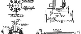
One of the drawing schemes is shown in Fig. 50. The broach shank 5 is passed through the hole of the workpiece 7 and the sleeve 8 of the device 6 installed in the support plate 9.
The left end of the broach is fixed in an automatic chuck, consisting of a housing 4, a special sleeve 10 with an internal diameter corresponding to the broach, and two crackers 3. In the position shown, spring 2, pushing apart part 1 connected to the rod of the power cylinder, and the housing 4, moves the crackers 3, as a result of which the latter capture the broach shank.
When the broach moves to the left, the hole is machined. During idling, the broach returns to its original position.
Housing 4, approaching device 6, rests against it and stops.
The piston rod and coupling 1, continuing to move and compressing the spring 2, move the sleeve 10 to the right, the crackers 3 fall into the groove a, and the movement stops. Now the broach shank can be freely pulled out of the hole in sleeve 10, inserted into the next part and, having installed it again, begin processing.
The machine operates with a full and simple cycle. With a full forward stroke cycle, the broach is supplied, the working stroke is slow, the adjusted working stroke is a slow working stroke when the calibrating teeth and stops are working. During the reverse stroke, the stroke is slowed down and the broach is retracted. A simple cycle differs from a complete cycle by the absence of feed in and out of the broach.
The full cycle of the machine includes:
- quickly bringing the broach to the working chuck and grabbing it
- slower travel with higher speed (which ensures full use of drive power)
- slow working stroke (to obtain the required roughness when operating the calibrating broach teeth)
- opening the auxiliary chuck and removing the broach from the part
- stopping the machine to unload the part
- reverse movement of the working slide after pressing the “Start cycle” button again
- gripping the workpiece with an auxiliary chuck at the beginning of the return stroke
- slowing down the speed at the end of the return stroke and opening the working chuck
- broach removal using auxiliary slides
- stop
An incomplete cycle is possible without the supply and removal of the broach, when the auxiliary units are not in operation.
To avoid sagging of the free end of the broach when it is fixed in only one of the cartridges, support rollers are provided that can be retracted.
Scheme of the broaching operation of the horizontal machine 7B56
Scheme of the broaching operation of the horizontal machine 7B56
The broaching movement is carried out using a hydraulic drive with two pumps. One of them, with a capacity of 200 l/min, serves to supply oil to the main (working) hydraulic cylinder, the other, with a capacity of 25 l/min, supplies oil to the auxiliary hydraulic cylinder. The hydraulic drive allows three cycles of operation: a full cycle, a simple cycle and an adjustment cycle. Full cycle work is carried out using long broaches (1200-1300 mm) with a rear shank. The broach is installed with the shank into the auxiliary chuck, which receives movement from the rod of the auxiliary cylinder. The broach moves, supported by a roller, to the working chuck. The chuck grabs the front shank of the broach and moves it along with the auxiliary chuck until it opens from the copier, carries out the working and return strokes, after which the auxiliary chuck grabs the rear shank of the broach and moves it to its original position.
A simple cycle is used when using short broaches. In this case, the broach is secured manually in a chuck mounted on a slide that receives horizontal movement from the main hydraulic cylinder along the frame guides. The auxiliary slide does not move during this cycle.
The setup mode is used when setting up the machine. This mode includes the tool movements necessary to prepare the broaching process.
The machine operates as a semi-automatic machine, but when equipped with automated devices for feeding and removing parts, it can operate in an automatic cycle and can be built into automatic lines. The machine is used in large-scale and mass production, and taking into account simple readjustment, it can be used in single and small-scale production.
One of the drawing schemes is shown in Fig. 50. The broach shank 5 is passed through the hole of the workpiece 7 and the sleeve 8 of the device 6 installed in the support plate 9.
The left end of the broach is fixed in an automatic chuck, consisting of a housing 4, a special sleeve 10 with an internal diameter corresponding to the broach, and two crackers 3. In the position shown, spring 2, pushing apart part 1 connected to the rod of the power cylinder, and the housing 4, moves the crackers 3, as a result of which the latter capture the broach shank.
When the broach moves to the left, the hole is machined. During idling, the broach returns to its original position.
Housing 4, approaching device 6, rests against it and stops.
The piston rod and coupling 1, continuing to move and compressing the spring 2, move the sleeve 10 to the right, the crackers 3 fall into the groove a, and the movement stops. Now the broach shank can be freely pulled out of the hole in sleeve 10, inserted into the next part and, having installed it again, begin processing.
The machine operates with a full and simple cycle. With a full forward stroke cycle, the broach is supplied, the working stroke is slow, the adjusted working stroke is a slow working stroke when the calibrating teeth and stops are working. During the reverse stroke, the stroke is slowed down and the broach is retracted. A simple cycle differs from a complete cycle by the absence of feed in and out of the broach.
The full cycle of the machine includes:
- quickly bringing the broach to the working chuck and grabbing it
- slower travel with higher speed (which ensures full use of drive power)
- slow working stroke (to obtain the required roughness when operating the calibrating broach teeth)
- opening the auxiliary chuck and removing the broach from the part
- stopping the machine to unload the part
- reverse movement of the working slide after pressing the “Start cycle” button again
- gripping the workpiece with an auxiliary chuck at the beginning of the return stroke
- slowing down the speed at the end of the return stroke and opening the working chuck
- broach removal using auxiliary slides
- stop
An incomplete cycle is possible without the supply and removal of the broach, when the auxiliary units are not in operation.
To avoid sagging of the free end of the broach when it is fixed in only one of the cartridges, support rollers are provided that can be retracted.
§ 6. HORIZONTAL TRAFFIC MACHINE 7B55. Technical specifications.
Section: LIBRARY OF TECHNICAL LITERATURE Short path https://bibt.ru<<Previous page Book table of contents Next page>>
The machine is designed for drawing through holes of various shapes, and when using special devices, for processing external surfaces.
When the machine is equipped with automated devices for feeding the workpiece and removing the part, it can be built into automatic lines.
Technical characteristics of the machine 7B55. Maximum traction force 100 kN; the longest working stroke of the slide is 1600 mm; working speed limits 1.5-11.5 m/min, return speed 20-25 m/min; broach inlet and outlet 15 m/min; overall dimensions of the machine are 7200 x 2200 x 1700 mm.
The main mechanisms of the machine and the operating principle of the horizontal broaching machine 7B55. (Fig. 119). The main hydraulic drive units are mounted in frame 1. The power cylinder rod 2 has a chuck for securing the broach, the right end of which is clamped in the auxiliary chuck 4. The piston rod is connected to the working slide, which, moving along the frame guides, serves as additional support. Devices for installing the workpiece or the workpiece itself, if its size is small, rests with its end against a stationary faceplate 3.
Rice. 119. Horizontal broaching machine 7B55
The 7B55 machine operates with a full and incomplete cycle. For a full cycle, long broaches are used. Auxiliary chuck 4 moves the broach by the rear shank to the left until the front shank of the broach enters the hole in the workpiece. Then the working chuck will grab this shank (the connection between the broach and chuck 4 will be interrupted using a special device) and will move the broach, carrying out a cycle of the following movements: slow working stroke, adjusted working stroke, slow working stroke when calibrating teeth are working, stop, slow stroke in in the opposite direction. Then the rear shank of the broach will re-enter the auxiliary chuck and the broach will be withdrawn. With a simple cycle, there is no feed in and out; in this case, short broaches are used, secured in the chuck manually.
The hydraulic circuit of the broaching machine 7B55 carries out the operating cycle of the machine. Piston pump 30 (Fig. 120) with a flow rate of 200 l/min (it is shown conditionally in the diagram) carries out the working and auxiliary strokes of the slide. The auxiliary hydraulic drive, which serves to remove and supply the broach, consists of a gear pump 1 with a flow of 25 l/min, built into the piston pump, and an auxiliary cylinder 12. From pump 1, oil is supplied to the support cylinder 20, to the central hydraulic distributor 32 and the control mechanism , in which four hydraulic valves are located, controlled by electromagnets 24-27. In the disk 34, which is pressed together with the hydraulic distributor 32 to the left under the action of the spring 33, there are five holes for screws 36. Screws 36 regulate the performance of the pump 30 by displacing the stator. When pressure is applied under the piston 35, it will rest against the screw 36 with its rod and limit the movement of the disk 34 and, accordingly, the hydraulic valve 32 connected to the stator piston 31.
Rice. 120. Hydraulic diagram of the machine 7B55
Broach supply for machine 7B55. When the electromagnet 9 is turned on, the hydraulic distributor 7 will move to the left and connect pipelines 3 and 8. Then the oil from pump 1 through pipeline 2 through the hydraulic distributor 7 and pipelines 3 and 8 will enter the hydraulic distributor 4 and move it to the left, while connecting pipelines 2 and 6. Oil will enter the rodless cavity of cylinder 12 and the broach will begin moving. At the end of the broach supply, after the PV limit switch 13 is triggered, the electromagnet 9 will turn off and the electromagnet 27 will turn on. Then the oil will go under the piston 35 and shift the stator of the pump 30 to the position shown in Fig. 120. At the same time, the broach with the left end will fall into the cartridge mounted on the rod of the working cylinder 19.
Slow work progress. Oil through pipeline 29 from the discharge cavity of pump 30 enters hydraulic distributor 23 and shifts it to the left, while oil enters cylinder 19 through pipeline 22, shifting it to the left. The displaced oil through pipelines 21 and 28 enters the suction cavity of pump 30 II. Excess oil is drained through hydraulic distributor 37.
Fast working stroke of the broaching machine 7B55. When the cam is pressed on the PV 17, the electromagnet 25 is triggered. The stator 31 will move even more to the left, the eccentricity of the pump block will increase and, accordingly, the pump performance will increase. At the end of the working stroke, the cam will press on PV 16 and the electromagnet 25 will turn off, the pump performance will decrease and the working stroke will slow down. At the end of the slow stroke, when PV 15 is triggered, the electromagnet 27 will turn off and a stop will occur.
Reverse stroke of the 7B55 machine. When the electromagnet 26 is turned on, the pump block 30 moves to the left, the pipeline 28 becomes a discharge one, and 29 a suction one. Through pipeline 28, oil enters hydraulic distributor 23 and moves it to the right; pipelines 21 and 22 will be connected to pipeline 28, and both cavities of the cylinder 19 will be connected to the discharge line. The piston, and, accordingly, the working slide moves to the right until the cam hits PV 17, and electromagnet 24 turns on. Due to a decrease in pump performance, a slow motion will begin. At the end of the reverse stroke, PV 18 will operate, turning off electromagnets 26 and 24. The slide will stop, the left end of the broach is released, and the right end is clamped in the auxiliary chuck.
Broach outlet 7B55. The limit switch 18 turns on the electromagnet 10, and the hydraulic distributor 7 will take the right position, connecting pipelines 3 and 5. Oil from pump 1 through pipelines 2, 3, 5 enters the hydraulic distributor 4, shifts it to the right, thereby connecting pipelines 2 and 11; Through them, the oil enters the rod cavity of the cylinder 12 and will move the broach until the PV 14 turns off the electromagnet 10.
Skip to navigation
Technical characteristics of the broaching machine 7B56
| Parameter name | 7B55 | 7B56 |
| Basic machine parameters | ||
| Machine accuracy class | N | N |
| Nominal traction force, kN(tf) | 100(10) | 200(20) |
| Maximum stroke length of the working slide, mm | 1250 | 1600 |
| Maximum adjusted stroke length of the working slide, mm | 1200 | 1715 |
| Distance from the bed to the axis of the hole for the faceplate in the base plate, mm | 250 | |
| Maximum outer diameter of the workpiece, mm | 600 | 600 |
| Dimensions of the working surface of the front support plate of the machine, mm | 450 x 450 | |
| Diameter of the hole for the faceplate in the base plate, mm | 160 | 200N7 |
| Diameter of the hole in the faceplate, mm | 125 | 130H7 |
| Faceplate diameter, mm | 280 | |
| Working speed, m/min | 1,5..11,5 | 1,5..11,5 |
| Adjusting the stroke speed | stepless | stepless |
| Recommended reverse speed, m/min | 20..25 | 20..25 |
| Recommended speed of feed in and out, m/min | 15 | 15 |
| Electrical equipment. Drive unit | ||
| Number of electric motors on the machine | ||
| Main motion drive electric motor, kW | 18,5 | |
| Hydraulic pump drive electric motor, kW | ||
| Cooling pump electric motor, kW | ||
| Total power of electric motors installed on the machine, kW | ||
| Dimensions and weight of the machine | ||
| Machine dimensions (length width height), mm | 6340 x 2090 x 1910 | |
| Machine weight, kg | 5200 |
- Grinding machine. Operating manual, 1977
- Ashikhmin V.N. Reaching out, 1981, p.90.
- Katsev P.G. Lengthy works, 1968
- Katsev P.G., Epifanov N.P. Broacher's Handbook, 1963
- Skhirtladze A.G., Novikov V.Yu. Technological equipment of machine-building industries, 1980, p.248.
- Tepinkichiev V.K. Metal-cutting machines, 1973, p.76.
Bibliography:
Related Links. Additional Information
- Repair of hydraulic systems of metal-cutting machines
- Designations of hydraulic circuits of metal-cutting machines
- Repair of gear hydraulic pumps
- Adjustment of milling machines
- Milling machine repair technology
- Adjustment of screw-cutting lathe 1K62
- Designations of kinematic diagrams of metal-cutting machines
- Methodology for checking and testing screw-cutting lathes for accuracy
- Methodology for checking and testing vertical drilling machines for accuracy and rigidity
Home About the company News Articles Price list Contacts Reference information Interesting video KPO woodworking machines Manufacturers
Specifications
Design features affect all main technical characteristics. The movable work table has T-shaped slots in which workpieces are fixed using clamps.
Dimensions and weight
Machine weight – 900 kg. The dimensions are such that this equipment can easily fit into a room of almost any size:
- length – 115 cm;
- width – 110 cm;
- height – 160 cm.
The vertical table has working surface dimensions of 550x195 mm.
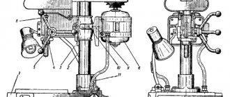
Vertical spindle
The vertical spindle is designed for cutter shanks with Morse taper 4. The adjustable distance between the end and the table is 22–312 mm. Other technical characteristics of the vertical spindle:
- distance from the axis to the end – 100 mm;
- head rotation angle – 45°;
- the greatest movement along the axis is 60 mm.
Vertical spindle rotation speed – 56–2450 rpm.
Vise
Vices also have their own technical characteristics depending on the design features:
- width x height of lips – 150 x 140 mm;
- the largest spread of the sponges is 50 mm;
- maximum rotation angle – 360°;
- scale division is 1 degree.
Overview of the machine model 7B55
The technical characteristics of broaching machines for working on metal include the following important indicators - the working traction force and the maximum amount of broaching movement. Domestic manufacturers produce various models of broaching machines for metalworking that can satisfy all the necessary needs of the customer. One of these machines is model 7B55.
Appearance of broaching machine 7B55
The technical device of this machine has the following description:
- the main part of the technological equipment is a welded, hollow inside frame, in the middle of which there is a powerful hydraulic drive;
- the drive itself consists of a power cylinder and a rod that moves horizontally along special guide slides;
- a cartridge is installed on the rod in which the broach is fixed;
- The machine diagram also has a special auxiliary chuck designed for fastening the end of the cutting tool.
During the working process, the auxiliary cartridge moves along a horizontally located slide together with broaching until it stops. At the end point of movement, their connection is broken using a special spring cam. After the cutting machine has completed the entire cutting operation, the broach returns to its original position and is reattached to the auxiliary chuck. Like most machines of this class, 7B55 only supports semi-automatic part processing. However, the technical characteristics of broaching machines allow for improvement by installing a CNC, which brings the entire working process to full automation.
Passport for horizontal broaching machine 7B56
Printing documentation: Minsk Machine Tool Plant named after S.M. Kirov Year of documentation printing: 1974 Number of folders: 4 Number of pages, sheets: 436
Find out the cost of documentation
The passport and documentation for this machine model are in our archive, in electronic form. The documentation set includes, in sections, according to the content:
1. Manual for the machine Contents: 1. Purpose and scope of application 2. Unpacking and transportation of the machine 3. Installation of the machine on the foundation 4. Machine passport 5. Brief description of the design and operation of the machine 6. Operating cycle of the machine 7. Electrical equipment List of purchased items 8. Hydraulic equipment 9. Lubrication of the machine 10. Preparing the machine for initial start-up and starting the machine 11. Setting up the machine and operating mode 12. Adjusting the machine 13. Safety instructions
2. Album of drawings - Bed. Assembly drawing 7B55-18-001SB - Attached frame. Assembly drawing 7B55-19-001SB - Working skids. Assembly drawing 7B56-27-001SB - Auxiliary slides. Assembly drawing 7B56-29-001SB - Mechanism for adjusting the stroke of the machine. Assembly drawing 7B56-35-001SB - Switching mechanism. Assembly drawing 7B56-36-001SB - Support roller. Assembly drawing 7B56-37-001SB - Support roller. Assembly drawing 7B56-38-001SB - Locking and unlocking mechanism. Assembly drawing 7B56-39-001SB - Working cartridge. Assembly drawing dU2443-001SB - Working cartridge. Assembly drawing dU2442-001SB - Auxiliary cartridge. Assembly drawing dU2443-001SB - Working cylinder. Assembly drawing U5113-001SB - Hydraulic cylinder. Assembly drawing U5172-001SB - Pump installation. Assembly drawing U5235-001SB - Hydraulic control panel. Assembly drawing U5618B-001SB - Faceplate 7B55-18-101 Drawings of wear parts
3. Accompanying documentation
4. Acceptance certificate
Diagrams and drawings of the machine: - Transportation of the machine in packaging - Layout of the foundation of the machine drawing - Setup diagram - Layout of the main components of the machine - Working slides drawing - Supporting roller in the main bed drawing - Mechanism for adjusting the movement of the machine drawing - Chuck working drawing - Supporting roller in the attached bed bed drawing - Chuck auxiliary drawing - Locking and unlocking mechanism drawing - Placement of electrical equipment on the machine - Electrical circuit diagram 7B55-00-022 E3 - Electrical connection diagrams of the machine 7B55-00-022 E4 - Electrical connection diagrams of the control panel 7B55-00-022 E4 — Electrical connection diagrams for the power supply 7B55-00-022 E4 — Electrical connection diagrams for the power panel 7B55-00-022 E4 — Electrical connection diagrams for the relay panel 7B55-00-022 E4 — Electrical connection diagrams for the electrical cabinet 7B55-00-022 E4 — Hydraulic diagram of the machine — Machine lubrication diagram
Brief description of the machine: The horizontal broaching machine model 7B56 is designed for processing, by broaching, through holes of various geometric shapes and sizes, both pre-processed and black, within the limits of the traction force of the machine and the stroke length of the working slide. However, when using special devices, they can also be used to stretch the outer surfaces of various profiles. The machine is characterized by high productivity, high precision, provides good quality of the machined surface and is widely used in mass and large-scale production. When processing holes, the time for readjusting the machine is insignificant, which makes it possible to successfully use the machine not only in conditions of mass and large-scale production, but also in conditions of small-scale and individual production. Having equipped the machine with automatic loading and unloading of parts, it can be built into automatic lines.
The consumer receives a machine packed in one box, in which the pumping unit is disconnected from the working hydraulic cylinder, and the attached frame is disconnected from the main one. Transportation of the machine, packed and unpacked, should be carried out according to the diagrams given on the sheets. When loading and unloading, do not allow the box to tilt to the sides, be hit by machines or the bottom, or have strong shocks when lifting and lowering. To protect the protruding parts of the machine from damage, it is necessary to install chocks under the ropes. To avoid damage, unpacking the machine should begin by removing the top shield, then removing the side and end shields. After opening the package, it is necessary to check the external condition of the components and parts of the machine, the presence of all kits and other materials according to the packing list. If a machine packed in a box is moved along an inclined plane on rollers, its angle of inclination should not exceed 15 degrees. In this case, it is not allowed: - Place rollers with a diameter of more than 50 - 70 mm under the box; — Place the box on its edge, turn it over and tilt it strongly;