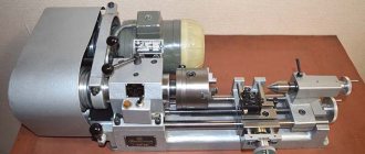
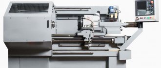
Functionality of the machine 1A616
The functionality of this equipment is represented by the operations listed below:
- turning the surfaces of parts of arbitrary shape (including their facing);
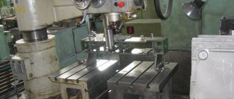
- spot drilling;
- cutting grooves of various depths;
- deployment of standard holes;
- thread preparation using a cutter or tap;
- formation of mesh corrugations.
The presence of a large number of various functions turns turret lathes into universal mechanisms, the advantages of which include their low cost.
This is interesting: Cutting modes during turning - calculation and selection
Providing feed and cutting motion
Jet lathe
The feed movement that the lathe support makes is communicated to it from the spindle assembly. In fact, the feed box of a machine of this model can provide 48 speeds, but due to the fact that some of these speeds coincide, only 22 are indicated in the device passport. In order to impart longitudinal movement to the support, it is necessary to use a gear coupling, and for the transverse feed of this unit The lead screw of the unit responds.
Feedbox 1A616 (click to enlarge)
In the event that it is necessary to cut a thread on the workpiece whose pitch does not exceed 6 mm, the support is connected directly to the machine spindle. If it is necessary to cut a thread with a large pitch, then to connect the support and the spindle, the search is turned on, and an intermediate step increasing the pitch is used.
The main movement in this lathe, as in devices of other models, is the cutting movement performed by the spindle and the metal workpiece fixed in it. From this movement, as mentioned above, the machine support is also activated, which can move in the longitudinal and transverse directions. The main elements of the drive responsible for the cutting movement are:
- two V-belt drives;
- 12-speed gearbox.
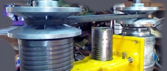
Gearbox 1A616
The gearbox of a lathe consists of three shafts installed in units with bearings, three moving blocks, each of which consists of two gears, and a single moving gear. By meshing gears with different parameters, the machine spindle is given different rotation speeds. Rotation from the gearbox is transmitted to the hollow shaft, and then, through a series of gears, to the machine spindle. In the event that the spindle needs to be given high rotation speeds, it is directly connected to the hollow shaft, for which a special cam clutch is used.
To control a lathe, which, according to even novice experts, is not very difficult, it is necessary to perform a number of manual operations. These include:
- turning the tool holder and installing it in the required position;
- movement of the tailstock, which houses the machine quill;
- installing the caliper in the required position.
Apron 1A616 (click to enlarge)
Kinematic diagram of a lathe model 1A616K
Kinematic diagram of a lathe model 1A616K
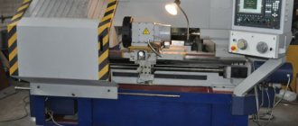
Operating principle of the universal screw-cutting lathe 1A616K
The workpiece is mounted in centers or secured in a chuck. Four cutters can be secured in the caliper tool holder. The hole making tools are inserted into the tailstock quill taper. By combining the rotational movement of the part with the translational movement of the cutter on the machine, cylindrical, conical, helical and end surfaces can be processed.
Design features. The machine model 1A616K uses a split cutting motion drive.
The drive pulley is mounted on the spindle between its supports, but the design of the rear spindle support allows the replacement of V-belts without dismantling the spindle.
Braking of the machine drive is achieved by connecting direct current to the stator winding of the electric motor.
Movements in a universal screw-cutting lathe 1A616K
Cutting movement is the rotation of the spindle with the workpiece. Feed movement is a rectilinear translational movement of the support with the cutter in the longitudinal and transverse directions from the roller.
The movement of the formation of a screw surface is a rectilinear translational movement of a caliper with a threaded cutter in the longitudinal direction from the lead screw.
Auxiliary movements are manual installation movements of the caliper, body and tailstock quill and rotation of the four-position tool holder.
Cutting movement
The cutting movement drive of the machine model 1A616K is divided. It consists of two V-belt drives, a nine-speed gearbox and a selector device in the spindle headstock.
The two-speed electric motor is connected to the input shaft of the automatic gearbox via a V-belt drive.
The three-shaft automatic gearbox (AKS-109) allows you to get 9 speeds on the output shaft.
Thus, the rotation from the output shaft of the AKS through a V-belt transmission goes to the input shaft of the spinel headstock: a total of 9 x 2 = 18 rotation speeds.
The selection of 1:1 and 1:8 in the spindle head allows 36 rotation speeds to be transferred to the spindle, but 15 steps coincide (35.5..900), as a result of which out of 36 speeds the spindle has only 15 + 6 = 21 different rotation speeds.
Feed movements in the machine
The feed movements of the caliper are borrowed from the spindle. Shaft X receives rotation through gears 34—44—22—34. The movable gear 34 on shaft X serves to change the direction of the caliper feed. When the gear shifts to the left, shaft X receives rotation from gear block B4, bypassing idler gear 222.
- Here and in the future, when describing kinematic diagrams, the pulley diameters in mm and the number of wheel teeth will be indicated by numbers expressing the indicated values.
- The possibility of direct engagement of gears 44 and 34 is conventionally shown in the diagram with a dashed line. This convention is subsequently applied in all similar cases.
To feed the caliper, replaceable gear blocks C1 and C2 are installed as shown in the diagram, and shaft XII is driven from shaft X through gears 30—66—36. Theoretically, the feedbox can provide 48 speeds. However, due to the close coincidence of a number of speeds, in practice the feed box gives only 22 different feed rates.
The intermediate shaft XIX and the running roller XXI connected to it by a safety clutch Mn receive rotation from the output shaft XVII of the feed box through wheels 23-55. Running roller XXI transmits rotation through a worm gear 2-35 to shaft XXII. The latter is connected to shaft XXIII by wheels 31–53.
The M6 fine-tooth clutch is used to engage the longitudinal feed of the caliper. The movement from shaft XXIII is transmitted to the caliper through the MB coupling, wheels 27-53, shaft XXIV and rack and pinion gear 14 - rack m = 2 mm. Transverse feed is carried out by lead screw XXVII (with the M5 clutch engaged), which receives rotation from shaft XXII through gears 50-35 and 47-13.
Movement of formation of a helical surface. To cut threads with pitches of up to 6 mm, the movement, as when feeding the caliper, is borrowed from the machine spindle. Threads with a larger pitch are cut when the search is turned on using the pitch increasing link. To do this, the gear block B4 is shifted to the right until its left gear 44 engages with gear 34 mounted on the hollow shaft V. In this case, the caliper will move from shaft V.
For cutting metric and inch threads, replaceable gear blocks C1 and C2 are installed in the same way as when feeding 30-66-36. To cut modular and pitch threads, replaceable blocks are rearranged so that the movement of shaft XII is transmitted by gears 36—66—55.
For some thread pitches, other options for installing replaceable blocks are used, in which the movement is transmitted by gears 25-66-55 or 36-66-30.
When inch and pitch threads are being cut (as shown in the diagram), the M2 jaw clutch is turned off. Wheel 51 is engaged with gear 30 of shaft XII, and gear 39 on shaft XV is engaged with gear 39 of double block 22, 39, freely sitting on shaft XIV. To cut metric and modular threads, clutch M2 is engaged, wheel 51 is disengaged, and gear 39 moves along shaft XV to the right until it engages with wheel 39, rigidly mounted on shaft XIV.
The caliper receives movement from the feed box through an M4 dog clutch, an intermediate shaft XVIII and a lead screw XX.
Auxiliary movements
Limb L of the longitudinal feed of the caliper receives rotation from shaft XXIV through gears 53-17 and gear 30-30-30-117 with internal gearing.
Repair features
Lathe 1k62d
Almost all components of the 1A616 machine have features for disassembling and replacing elements. To avoid mistakes, work should be carried out by carefully studying the drawings contained in the equipment operating instructions. Also, a lot of information on carrying out individual repair operations can be found on special resources.
To carry out complex work, for example, replacing a dog clutch, you should strictly follow the instructions given in the documentation for the equipment. Here you will find all the data related to repairs, allowing you to adjust the bearing or configure the operation of an entire functional unit of the machine.
How to remove a cartridge
Some jobs are quite simple. In particular, removing the cartridge. It is of a cone type, fixed with four faceplate nuts on bolts. To remove this element of the assembly, just unscrew them. It is worth noting separately: in some modifications of the machine, a removable faceplate is not used; instead, a permanent chuck mounting is located on the spindle.
How to remove the faceplate
Removing the faceplate is difficult. It is screwed very tightly onto the gear shaft of the headstock, the mass of the part is quite large, so turning the connection manually is almost impossible. Disassembly experience without the use of special tools has shown the effectiveness of the following options, which require the use of gearbox gears.
- Move the chuck jaws apart and place a crowbar or a thinner piece of metal between them. Turn the spindle so that the lever is located in a position convenient for lowering with force, just above the head. Turn on the transmission gearbox to minimum speed and turn on the search. When starting to rotate, sharply pull the rod down. This operation is potentially dangerous, both due to injury and damage to the elements of the box.
- Clamp a hexagon with a spanner on it or a metal rod across the axis in the chuck. Rotate the spindle so that the end of the lever rests on the rear guide of the bed. Switch the gearbox to low speed, reverse rotation and turn on the drive. To avoid damaging the surface of the guide, it is recommended to place a board or other damper under the lever.
These methods are used for manual disassembly. However, to carry out repairs of this kind, it is recommended to invite professionals with special equipment.
Gearbox repair
If the tension of the drive belts is adjusted, the gearbox is repaired. To do this, the fastening screws are unscrewed, adjustments are made with the appropriate nut for each pulley, after which the fastening elements are installed in place.
Replacing V-belts for a twelve-speed gearbox is also not difficult. To do this, the lubrication system is partially dismantled. Remove the cap, flange, screws and supply tubes. Afterwards, screw the M12 screws into the holes provided for this until the axle box comes out of the headstock. Insert the belts onto the seam and perform all the operations performed in the reverse order.
Purpose and scope of screw-cutting lathe
Drilling machine bosch pbd 40: customer reviews, characteristics
This device is intended for a number of turning operations:
- cutting metric, pitch, inch and modular threads, as well as Archimedean spirals;
- processing of hardened bearings;
- turning of materials of different types, using shock loads that do not affect the accuracy of processing parts;
- making cuts using carbide tools.
1K625 belongs to the group of frontal lathes, which allows processing short workpieces with large diameters.
Design
The technological solutions used in the manufacture of this model of the machine in its design make it possible to perform a wide range of work with high precision.
Headstock
Located on the left side of the frame, it has the following fixed inside its upper part:
- spindle;
- gearbox
A jaw chuck, which is flanged to the protruding end of the spindle, is used to hold the workpiece before it begins to rotate. The electric motor is installed in the engine compartment, which is located in the lower part of the headstock.
Caliper
The speed of the caliper is set by the transmission setting range. The functions of the support include:
- implementation of transverse feed of the cutter;
- implementation of longitudinal feed of the cutter.
The caliper is driven by an apron mechanism, which is rotated by a shaft (to ensure turning operations) or a lead screw (to perform threading).
Tailstock
The design features of this unit allow processing of flat cones, which is achieved using its transverse displacement. By connecting this assembly and the lower part of the caliper (using a special clamp), you can drill and mechanically move it away from the caliper.
Gearbox
The feed box is fixed on the frame, which is located under the headstock. The box has shafts on which are located:
- Norton mechanism block, stepped (Fig. 12);
- gear blocks 6, 13;
- switchable clutches 1,2,4,5,7,14,15.
Clutch 7, moved to the right position, ensures rotation of the lead screw 9, and the drive shaft 10 begins to rotate when the overrunning clutch 11,12 is switched to the left position.
Apron
The housing directed towards the caliper carriage contains an apron mechanism (Fig. 14):
- worm wheel 3 rotates due to the influence (through a series of gears) of the drive shaft;
- The rotation of shaft I occurs with the help of a gear wheel of the corresponding shafts II and III; couplings with end teeth 2, 4, 10, 11 are located on them.
Clutches with end teeth ensure the process of turning on and moving the caliper in two planes, in four directions:
- for movement in the longitudinal plane it is necessary to use rack and pinion wheel 1;
- for movement in the transverse plane, it is necessary to use a screw that rotates under the influence of a gear wheel.
Handle 8 performs control functions for the lead screw 6 and the nut 7. The lead screw and shaft are locked using a shaft with cams 9.
Important! This lock prevents the caliper from feeding when turned on at the same time.
Electrical equipment
The purpose of the electrical equipment of the device is aimed at connecting to a three-phase alternating current network equipped with an insulated or solidly grounded neutral wire. Electrical components of the machine:
- control circuit - 50 Hz, 110 V;
- power circuit 3–50 Hz, 380 V, (220 V on special order);
- local lighting circuit - 50 Hz, 36/24 V.
Principle of operation
The operating principle of a lathe is as follows: after assembling, installing and connecting the machine, a workpiece or part is fixed in the designated units, after which the machine is started and work begins, for example, the required amount of material is removed with a cutter.
If necessary, you can use additional equipment (for example, for grinding or drilling), which significantly expands the range of tasks performed by the equipment.
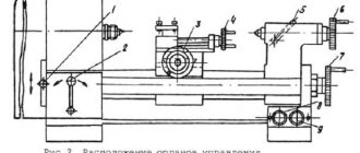
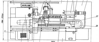
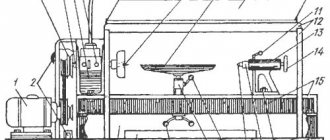
Location of the main components and controls of the 1A616K screw-cutting lathe
Location of the main components and controls of the 1A616K lathe
1A616K Main components of a screw-cutting lathe
- 11. Bed with gearbox AKS-109
- 21. Headstock with a pick-up device, a pitch increasing link and a reversing mechanism
- 80. Built-in wardrobe with electrical equipment
- 14. Control roller locking mechanism
- 30. Feed box
- 31. Apron with feed mechanism
- 32. Caliper with quick-acting four-position tool holder
- 33. Guitar replacement gears
- 40. Tailstock
- 51. Cooling system
- 72. Protective cover
- 78. Cartridge protection device
Specification of controls for lathe 1A616K
- 3. Handle for setting the thread pitch or feed amount;
- 4. Handle for setting the thread pitch or feed amount;
- 5. Handle for setting the thread pitch or feed amount;
- 6. Button for turning on the lead screw or lead shaft;
- 7. Handle for setting the normal or increased pitch of the thread being cut;
- 8. Handle for changing the direction of feed;
- 9. Switching handle (1:1, 1:8);
- 10. Handle for manual transverse movement of the caliper;
- 11. Handle for turning and securing the four-position tool holder;
- 12. Screw securing the caliper carriage to the frame;
- 13. Handle for manual movement of the upper part of the support (cutting slide);
- 14. Handwheel for manual longitudinal movement of the caliper carriage;
- 15. Button to turn off the rack and pinion gear when cutting threads;
- 16. Handle for turning on and off the longitudinal feed of the caliper;
- 17. Handle for turning on and off the transverse feed of the caliper;
- 18. Handle for turning the lead screw nut on and off;
- 19. Handle for securing the tailstock quill;
- 20. Transverse displacement of the tailstock housing;
- 21. Lever for securing the tailstock housing to the bed guides;
- 22. Handwheel for moving the tailstock quill;
- 23. Cooling pump activation handle;
- 24. Input switch;
- 25. Engine speed control handle (750, 1500);
- 26. Gear shift knob (1..9) in an automatic transmission (AKS);
- 27. Belt tension screws on the spindle headstock;
- 28. Electric motor belt tension screws;
- 29. Handles for turning on, turning off and reversing the main electric motor.
Specifications
The parameters given in the technical data sheet help determine whether this is the device you need for work. We invite you to consider the information provided.
Main settings
- Type - screw-cutting, universal.
- Series - 1A616.
- Accuracy - N (normal).
- The height of the centers is 165 mm.
- The distance between centers is 710 mm.
Spindle
Shaft for securing the workpiece in the chuck:
- Speed limits (forward and reverse rotations) 9–1800 rpm (if necessary, can be ordered with speeds from 11 to 2240 rpm).
- Hole diameter 35 mm.
- Internal Morse taper N5.
- The spindle is braked and the handles are locked.
Caliper and feed
Caliper (support) - a movable element, a unit for securing cutting tools or workpieces:
- Tool holder - 4 cutters.
- Cutter holder (largest dimensions 20x25).
- From the supporting surface to the center line 25 mm.
- From the center axis to the edge of the tool holder 170 mm.
- One front caliper with one cutting head.
Moving options:
- Longitudinal max 670 mm (same values by hand, by roller and by screw).
- Transverse max 195 mm (by hand and with a screw, with a roller this is not possible).
For one dial division:
- Longitudinal 1 mm.
- Transverse 0.05 mm.
For 1 revolution of the dial:
- Longitudinal 110 mm.
- Transverse 5 mm.
Feeds - movement of a cutting element or workpiece in one revolution or working stroke:
In the machines of this series, the limits of longitudinal and transverse feed are set in the range of 0.065 - 0.91 mm/spindle revolution.
Cutting slide
One of the caliper elements. A holder for cutters is attached to it. It can be moved manually along the rotating part of the caliper.
- Maximum rotation angle 90°.
- Scale division, price 1°.
- Maximum movement 120 mm.
- One dial division, price 0.05 mm.
- One revolution of the dial provokes a movement of 3 mm.
Tailstock and frontstock
Tailstock is a unit that helps in supporting the part being manufactured. You can also attach a tool for external processing of the product in it. Under difficult working conditions, it is possible to secure the structure using a tightening bolt and nut.
- Internal Morse cone 4.
- The quill moves a maximum of 120 mm.
- One division of the quill movement scale = 1 mm.
- Lateral displacement 10 mm (forward and backward).
The headstock is a mechanism that moves, receiving impulse from the gearbox through belts and a relieved take-up pulley. Thanks to him it is possible:
- increase eightfold the transmission of motion between the feed and the spindle when cutting threads;
- cut right and left hand threads.
Electrical equipment
The machine operates with a main motion electric motor:
- Power 4 kW.
- 1450 rpm at 50 Hz.
cooling pump:
- Power 0.125 kW.
- RPM 2800 at a frequency of 50 Hz.
Electrical equipment of lathe 1A616K
The machine is equipped with two three-phase electric motors;
DG electric motor of the main movement drive type A02-41-4 with a power of 4.0 kW, 1430 rpm, 220/380 V.
The electric pump for supplying coolant to the cutter is type PA 22 with a power of 0.12 kW, 2800 rpm, 220/880 V.
The machines are manufactured with electrical equipment designed to operate at a voltage of 380 V, both in power circuits and in control circuits.
The local lighting lamp is powered by a voltage of 36 V from a step-down transformer T
According to the order conditions, machines can be manufactured with an operating voltage of 220 or 500 V.
Specifications
This section provides technical characteristics of the machine itself and its individual components and elements.
Main settings
It is allowed to use parts for processing if they do not exceed the following dimensions:
- 500 mm above the bed;
- 260 mm above the caliper;
- 45 mm in the spindle cavity.
In this case, it is permissible to use parts with a length of 1000, 1400, 2000 mm; the specific size depends on the modification of the equipment used.
The machine allows you to cut different types of threads:
- metric threads - 44;
- inch threads - 38;
- modular threads - 20;
- pitch threads - 37;
- Archimedes spiral - 5.
Spindle:
- Diameter of through hole in spindle, mm: 47.
- Largest rod diameter, mm: 45.
- Number of speed steps for direct spindle rotation: 24.
- Direct spindle rotation frequency, rpm: 12.5..2000.
- Number of spindle reverse rotation frequency steps: 12.
- Spindle reverse rotation frequency, rpm: 19..2420.
- Size of the internal cone in the spindle, M: Morse 6.
- Spindle end according to GOST 12593-72: 6K.
Caliper:
- Maximum stroke length of the carriage, mm: 930, 1330, 1920.
- Maximum lateral stroke of the caliper, mm: 300.
- Maximum stroke of the upper support (cutting slide), mm: 150.
- Number of longitudinal feed stages: 49.
- Limits of longitudinal working feeds, mm/rev: 0.07..4.16.
- Number of cross feed stages: 49.
- Transverse working feed limits, mm/rev: 0.035..2.08
- Speed of fast movements of the caliper, longitudinal, m/min: 3.4.
- Speed of fast movements of the caliper, transverse, m/min: 1.7.
- Number of metric threads cut: 44.
- Limits of metric thread pitches, mm: 1..192.
- Number of inch threads to be cut: 38.
- Limits of pitches of cut threads inch: 24..2.
- Number of modular threads to be cut: 20.
- Limits of pitches of cut modular threads: 0.5..48.
- Number of pitch threads to be cut: 37.
- Limits of steps of cut pitch threads: 96..1.
Electrical equipment:
| Type | Model | power, kWt | Node, purpose |
| Electric motor | AO2-52-4F | 10 | main drive |
| Electric motor | AOL2-12-4F | 0,8 | Fast travel |
| Electric motor | AOL2-22-6F | 1,1 | Hydro station |
| Electric motor | PA-22 (pump) | 0,125 | Cooling pump |
In total, the machine is equipped with four electric motors.
Dimensions and weight:
- machine weight (RMC = 1000), t: 2.4
- machine dimensions (length/width/height) (RMC = 1000), mm: 3212x1216x1349
Basic equipment and technical characteristics of the equipment
The set of 1A616 machines includes samples of carbide cutters, which, if necessary, are used for cutting threads. In addition, it has a special set of high-speed cutting tools.
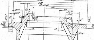
The machine has the following operating characteristics:
- The maximum length of workpieces to be processed is 71 cm.
- The range of turning performed on the machine is 66 cm.
- The maximum size of the installed blanks, fixed on top of the support, is 18 cm, and directly above the frame – 32 cm.
- The diameter of the working shaft for the spindle is 3.5 cm.
- The weight of the frame with attachments is 1.5 tons. The threaded end of the spindle shaft is of the “6K” type.
And finally, the dimensions of the machine body in the classic design are 2.1 x 1.22 x 1.2 meters.
Electrical system of the machine
The electrical circuit of this model lathe includes the following elements:
- three fuses;
- switch installed at the input;
- lamp for illuminating the work area;
- voltage relay;
- switch for lighting lamp;
- contactors that control stopping the engine, turning on its operating and reverse operation;
- a switch that supplies voltage to the pump supplying coolant;
- a relay responsible for controlling the engine rotation speed;
- a relay responsible for controlling the engine stop contactor;
- a step-down transformer;
- machine control switch;
- load level indicator;
- selenium type rectifier.
Electrical circuit diagram of the 1A616 machine (click to enlarge)
The machine has two electric motors, each of which solves its own problem:
- three-phase electric motor PA22 with a power of 0.12 kW, with a rotation speed of 2800 rpm, operating on a voltage of 220/380 V, drives the pump that supplies coolant to the cutting zone;
- three-phase electric motor A02-41-4 with a power of 4 kW, with a rotation speed of 1430 rpm, operating on a voltage of 220/380 V, is used as the main drive of the machine.
To equip industrial enterprises, lathes operating on a voltage of 380 V are used, and for operation in a home workshop, models operating on an electrical network with a voltage of 220 V are optimal. In addition, upon special order, modifications of a lathe operating on an electrical network with a voltage of 220 V can be produced. voltage 500 V.
Kinematic diagram of the 1A616 machine (click to enlarge)
Power for the lighting lamp, which operates at a voltage of 36V, comes from a step-down transformer present in the electrical circuit of the machine. A special feature of this lathe is that its design does not have a motor responsible for the high speed of its support. Fast and at the same time smooth stopping of the engine, during which it does not heat up, is ensured through the use of direct current.
Description of the control circuit for the main drive of the machine model 1A616K
The electrical control circuit is designed to switch speed levels and reverse the machine spindle,
For stepwise switching of speeds, an automatic gearbox of the AKS109D6.3 type is used, made on ETM electromagnetic clutches. The box has 9 speeds.
The spindle is started and stopped by turning on and off the electric motor Ml, which is controlled by starters K1 and K2, switch P2 and a roller with two handles in three positions:
- upper - working stroke
- average - stop
- bottom - reverse
The AKS is controlled by a biscuit switch mounted on the front wall of the spindle head, and the spindle is braked by a transistor delay unit BZ and relay P2.
In the BZ block, to increase the time constant (R=C), a transistor control circuit for turntable P2 is used. Transistors T1 and T2 are connected according to a common collector circuit. The time constant (delay time) is adjusted by shunting the input resistance with resistor R5.
Electrical circuit diagram of a 1A616 screw-cutting lathe.
The electrical circuit diagram of the universal screw-cutting lathe 1A616 is shown in the following figure:
You can download for free the electrical circuit diagram of the 1A616 screw-cutting lathe with specifications and in excellent quality from the link below:
the 1A616 screw-cutting lathe is shown in the following figure:
You can download this version of the electrical circuit diagram of the 1A616 screw-cutting lathe for free with specifications and in excellent quality from the link below:
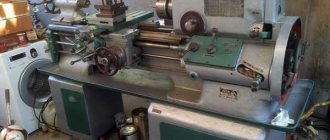
Description of the machine
Model 1A616 has average weight and dimensions and is designed to work in large-scale production conditions. The machine is designed to work with small-sized parts. It allows you to use a wide range of tools for processing - both high-speed tools and those made of carbide materials.
The unit can handle workpieces of conical, cylindrical, oval shape. During operation (description of the interaction scheme), the part rotates relative to the cutter or other working tool. The design of the spindle and chuck allows the machine to process workpieces of small to medium weight.
The greatest functionality of the 1A616 model is observed in the area of thread creation. The machine allows you to do:
- pitching;
- inch;
- modular;
- metric thread.
The pitch of the threads can vary within wide limits. The following groups of operations are also available:
- turning of cylindrical and conical surfaces;
- processing of workpiece ends;
- drilling;
- cutting grooves, grooves;
- development of holes, both conical and cylindrical;
- knurling of corrugations with a mesh pattern.
Cutting threads in holes can be done either with cutters or with a tap. Thanks to such a wide range of functions, the 1A616 machine is very popular and receives positive reviews from professional turners.
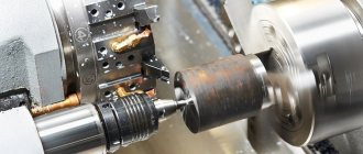
Principle of operation
The 1a616 lathe functions very simply. The master fixes the workpiece in the chuck or places it on centers. After this, the cutters are mounted in the tool holders, and the tool for creating holes is mounted in the quill. Now you can start processing any surface, be it a cone, end, cylinder or anything else. The configuration of the workpiece can be anything - the machine will cope with the task in any case.
The drive pulley is installed between the spindle supports. In turn, the master can quickly replace belts without removing the spindle. This is quite convenient and contributes to increased productivity.
An important feature of the 1a616 model is the presence of a separate format cutting drive. The design also includes a DC stator connected to the winding. This allows for quick braking if necessary.
Controls
The machine support is shifted along a screw axis in manual mode (its maximum value reaches 195 mm). For longitudinal movement, a special shaft is used, providing a maximum shift of 670 millimeters. The feed parameters are almost the same; they are selected by the operator within the range from 0.065 to 0.91 rpm.
It is possible to replace the gears included in the mechanism with their precision analogues, which guarantees ultra-precise threads. There is no need to change the feed speed to prepare standard cuts. When operating in precision mode, the lead screw is driven directly.
Machine speed box
The specificity of the 1A616 device allows switching the speed of the working shaft in a wide range of torques. For this purpose, it is equipped with a 12-speed gearbox, thanks to which the accuracy of thread cutting is noticeably increased.
Please note: The movable box mount allows you to adjust the tension of the transmission belts. To control the gearbox, there are two handles on the frame that can be moved left and right
One of them is designed for 4 positions, and the other for three
To control the gearbox, there are two handles on the frame that can be moved left and right. One of them is designed for 4 positions, and the other for three.
Headstock
This unit is located in front of the frame and is driven by a 12-speed gearbox via a belt drive. Features of the torque-transmitting coupling design make it possible to increase the number of processing modes from 12 to 24. And since 3 positions are already provided in the selector device, the main unit can operate at a total of 21 rotational speeds.
Additional information: Switching from the transfer mechanism to the clutch and back is carried out using a special handle.
The front part of the tapered journal of the shaft is fixed in a double-row roller bearing, the location of which can be adjusted. Its other end is fixed in a stationary single-row plain bearing. In addition, a ball bearing is built into the unit, which takes the longitudinal load from the shaft.
Apron
In the product model 1A616, the closed design of the apron is extremely simplified. It includes mechanisms that ensure the movement of the caliper in two directions. It is carried out using 2 handles, each of which is responsible for its own direction. They are launched in a circular motion toward you, and stopped by the same displacement, but only away from you.
Screw-cutting lathe support
The feed movement of the caliper is transmitted to it from the drive spindle assembly. Its design provides not only longitudinal, but also transverse displacement.
At the same time, belt drives are responsible for the longitudinal cutting movement, as well as the previously discussed 12-speed gearbox.
Lathe tailstock
The main purpose of the rear unit is to reliably support oversized workpieces during processing, ensuring their static and dynamic alignment. In addition, it helps to fix the cutting tool. The unit itself is attached to the frame guides by means of a bolted joint controlled by a special handle.
Design and principle of operation (operating instructions)
A screw-cutting lathe has in its design basic mechanisms and elements, such as:
- The gearbox has 12 gears and is located on the inner wall. It is provided for its movement in the vertical direction to ensure tension of the belts. The rotation of its mechanisms directly depends on the engine from which the impact is transmitted thanks to the clinomeric transmission. The box is controlled by 2 handles that rotate left and right, one of which can be set in 4 positions, and the other in 3.
- The front unit of the machine is attached to the front part of the stationary base of the unit. Its mechanisms rotate thanks to the operation of the gearbox, the impact is transmitted through a belt drive. The main shaft of the unit, thanks to the overdrive gears, receives 12 rotational speeds and another 12, thanks to the gear coupling, for a total of 24 different gears, 3 of which coincide with the overdrive and without its influence. This assumes that the main shaft receives 21 speeds. Using a special handle, the brute force or clutch is launched. The front journal of the machine shaft has a conical shape and is located on a special double-row rolling bearing, which can be adjusted, and the rear journal is located in a single-row bearing. The longitudinal load on the shaft falls on its ball bearing, located at the rear of the housing.
- Unit apron – movements of the carriage and tool holder in the axial and perpendicular directions are carried out due to 2 fine-tooth couplings located in the apron. The carriage and tool holder are driven by two handles, one of which is responsible for the longitudinal movement of the carriage, and the other for the perpendicular movement of the lower part of the tool holder. Starting is done by turning the handles towards you, and stopping - away from you. Another handle launches the uterine nut. When the handle is raised up, it stops the nut, and when lowered down, it turns it on. The locking mechanism necessary to prevent the synchronized start of the feed from the roller and the lead screw is also located in the apron of the device. Thanks to a special retractable button located there, the rack and pinion gear is removed from engagement with the rack.
- Tool holder - moves axially, following the guides of the machine base, and perpendicularly, following the guides of the carriage, thanks to its cruciform design. Its movements can be carried out mechanically or using a flywheel (manually). The upper part of the tool holder can move along its guides and rotate in both directions by 90°.
- Rear unit - supports long blanks during processing using centers - static and movable - and also secures cutting tools. Thanks to the handle, the unit is secured to the guides of the machine base. For high modes, for reliable fastening, the design of the device provides a special bolt and nut.
Rules of operation and care
When working with this device, as with any other machine that operates at high speeds of rotation of objects, it is necessary to adhere to basic safety rules.
Important!
Your health and future performance depend on following safety precautions.
- When setting up or cleaning the device, the power handle must be in the neutral position.
- It is forbidden to change gears at full speed.
- You need to use a protective screen.
- During operation, the tailstock must be securely secured with the appropriate handle and the bolt securely tightened.
- It is necessary to check that the nuts are securely tightened.
- Without the guitar gear enclosure, operation is prohibited.
- Before opening the cabinet with electrical appliances, the unit must be disconnected from the network.
- During operation, all doors must be tightly closed and the machine reliably grounded.
Care:
- Wiping open parts of the structure.
- Carefully monitor the level of oil and other necessary fluids.
- Carry out preventive maintenance regularly.
Intake stroke and metal cutting
The cutter holder receives feed movements from the main shaft of the device, as a result of which the tooth moves in a straight line. Based on the technical data sheet of the unit 1A616, the feed box is capable of providing 48 speeds. But in reality there are only 24 of them, since the speeds are the same. A clutch with fine teeth performs the function of launching feeds towards the axis, the lead screw is responsible for the perpendicular inlet.
Read also: How to use polyurethane foam without a gun video
The electric spindle of the 1A616 machine serves as a tool holder in situations where you need to cut small threads up to 6 mm. Increased shear and overhaul are used only when there is a need to cut at a larger stroke. To do this, you should point the wheel block to the right until the hollow shaft gear grabs the left circumference of the unit block. The cut represents the same movement of the drive shaft and the workpiece. Such rotation directs the cutter holder in an axial, and additionally perpendicular course, relative to the motor shaft. Movement is achieved due to the separate drive of the device, which consists of:
- caliper with 4 positions;
- 12-speed gearbox;
- 2 V-belt drives.