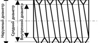
Measuring the internal diameter of a thread
The internal diameter of the cutting is controlled by a measuring device with pointed legs - calipers.
To organize computational work, you need to install the tool on a template part using a threaded gauge, and then make a comparison with the original internal diameter of the threaded connections. The caliper must be at an angle relative to the axis being measured. Also, measuring internal threads can be carried out with instruments for cylindrical threads. This is because the inside diameter has a smooth surface, which is ideal for the shape of the tips used in these instruments. Verification of the obtained measurements is done using plug gauges.
Diameter measurements
How to measure diameter with calipers? There are parts with a constant and variable cross-section along the length. The latter include, in particular, reinforcing bars. How to measure the diameter of reinforcement with a caliper? It all depends on the reinforcement profile, which can be:
- ring;
- sickle-shaped;
- mixed.
Measuring the inner diameter with a caliper
It is easiest to measure such reinforcement parameters in the second case. First, use external measuring jaws to determine the height of the protrusions of the profile, and then use a depth gauge to determine the size along the depression. Measurements must be taken in two mutually perpendicular directions, since reinforcement, and even not produced at specialized enterprises, often has an oval cross-section. After this, the most suitable value is found using tables of standard reinforcing profiles (special accuracy is not required here). How to measure the diameter of reinforcement with a caliper if it has a different type of profile? Here, instead of the diameter of the protrusions, the diameter of the protruding part of the crescent-shaped notches is determined, and then proceed in the same way as in the previous case.
Measuring the outer diameter of a pipe
When measuring the internal dimensions of pipes, use the internal measuring scale of the tool. How to measure the thickness of a pipe with a caliper, especially if the gap is small? It is enough to calculate the difference between the outer and inner diameters and divide the result by two.
Measurement methods
There are quite a large number of different ways to determine the thread pitch. All of them are characterized by their own specific features that need to be taken into account. Common methods include:
- Using a regular ruler.
- The use of a special tool that can be used to determine the value in question. A thread pitch meter can be purchased at a specialty store.
- A caliper is a precision instrument. It is used quite often due to its high accuracy and versatility in use.
All of the above methods allow you to obtain fairly accurate data. The easiest way to take measurements is to use a thread-finding tool, but you can get by with a regular caliper.
Nuances of measurement
There are a few guidelines to keep in mind when using a caliper. An example is the information below:
- If there is a plate between the head and the end part of the product, then in this case it is recommended to use the main measuring scale and depth gauge. With such a process, it is possible to obtain indicators of the thickness of the washer, the height of the head, and the thickness of the intermediate element. Such data allows you to calculate the main parameters of a threaded connection.
- The accuracy of the results obtained can be significantly increased by cleaning the surface from various contaminants. To do this, you can use an abrasive material or special liquids to remove corrosion.
You can carry out the procedure in question yourself. As a rule, there are no problems with this.
In conclusion, we note that manufacturers indicate the pitch and many other important indicators. As a rule, they are applied to the head or other element.
Source
Concept of thread pitch
Threads are used to connect a wide variety of products. To determine the bolt thread, you need to consider the distance between the same sides of the profile. The features of this concept include the following points:
- To determine the main parameters, a measurement is required.
- An inaccurate result can be determined by using a ruler.
- To increase the accuracy of measurements, you need to analyze several threads. That is why, depending on the length of the threaded surface, an analysis of 10 to 20 turns is carried out.
- It is recommended to take measurements in millimeters. In some cases the number is converted to inches.
The distance between the depressions can be measured using a special tool. The thread gauge is represented by a combination of special steel plates that have special cutouts. Various values are applied to the surface.
How to measure a nut
Most nuts have metric threads. Measuring the thread diameter will require a little more steps than in other cases. If possible, it is recommended to check the size of the bolt or screw used for it rather than the nut itself. This way you can achieve a more accurate result.
The value obtained after measuring the internal thread is an indicator of the internal diameter din.
In order to accurately determine the diameter of the metric thread of the hardware, you will need to find out the correspondence between din and the outer diameter of the bolt used. This is done using a special table.
Accuracy is controlled through the use of certain pass-fail gauges. One part should connect well with the nut, the second part, on the contrary, should not.
The nuts differ in appearance, and it is easy to determine upon detailed inspection. To find out the standard of the fastener, you may need to measure the height of the hardware, since there are high, low, extra high and other options.
Turnkey dimensions are also used to classify hex nuts. This is explained by the fact that hardware also differs in its types.
To accurately measure the thread pitch, it is possible to use the method considered in the case of a bolt. You will need a thread gauge or you will have to count the number of turns at the required interval.
Determining the dimensions of inch nuts
To check the thread dimensions of an inch nut, you need to examine the threads of the bolt or other hardware used with it. If you don’t have a suitable one at hand, but have information about the presence of an inch thread, then use the appropriate thread gauge. Do not forget to divide the resulting value by 25.4 mm.
Determining washer dimensions
For washers, a short designation in the form D is used, which stands for the diameter of the metric thread of the hardware used for the fastener.
To accurately measure indicators, a ruler or caliper is suitable. The result is a value that is slightly higher than the figure in the notation. This is explained by the fact that free movement is required during installation, which requires a small gap.
So, you have a bolt or nut with unknown thread parameters, and there is no measuring tool at hand other than a ruler. Let us immediately warn you that using a ruler can only get a rough result, so if you are going to regularly take such measurements, it is better to purchase a thread gauge or caliper.
Examples of measurements with calipers
A caliper is a convenient and easy-to-use measuring tool. Its proper use allows you to measure linear quantities in various situations, and for a variety of objects, from tire tread to plastic flexible tubes. How to measure with a caliper - examples and sequence - these issues are discussed below.
Measuring thread pitch without a thread gauge
Parts with external thread
Often the need to determine the thread pitch arises sporadically, at one time. And, of course, in such a situation there is no thread gauge at hand, and it makes no sense to buy one for one-time measurements. It will be useful to learn how to measure the thread pitch with a ruler or caliper. These measuring tools make it quite easy to determine the desired parameter.
The easiest way is to measure the threads of a bolt or other externally threaded part. When measuring a metric thread, it is recommended that you first attach the ruler to the threaded part and try to align the millimeter divisions of its scale with the tops of the ridges of the threaded profile. If they coincide, then the step is 1 mm. Otherwise, you will have to carry out slightly more complex measurements.
To determine the thread pitch, you need to count the number of turns on a section of a rod of a certain length, for example, 10 mm or 20 mm. To obtain a more accurate result, it is recommended to take measurements on a 20 mm area. The required length is measured by applying a ruler to the bolt shaft, or using a caliper. It would be more accurate to measure the bolt thread pitch with a caliper. In the measured area, count the number of turns. After this, the length of the section must be divided by the resulting number of turns minus one turn. As a result, we obtain the value of the thread pitch.
When determining the pitch of an inch cutting, it is necessary to measure the length of the rod equal to one inch (25.4 mm). For accurate measurements, it is better to use a ruler or caliper with an inch scale. The number of turns in this area will be the thread pitch. If the length of the threaded section is less than one inch, then you need to determine the number of turns in a section of half an inch (12.7 mm), and then multiply the result by 2.
Internally threaded parts
There are two ways to measure the thread of a nut or other internally threaded part without a thread gauge. The first method involves selecting an exactly suitable counter bolt and then measuring its thread pitch. If you can’t find the counter bolt, then you need to use a strip of paper (this is method No. 2).
It should be pressed against the thread so that an imprint of the profile remains on the paper. You can improve the visibility of marks by tracing the edges with a marker. After this, on paper you need to mark the distance between the extreme marks with a ruler and count the number of turns. Then the resulting distance is divided by the number of turns minus one turn. Instead of measuring paper using this method, you can use a pencil, match or other soft wood product of a suitable size, which is pressed against the thread.
The process of measuring turns
When considering how to determine the thread pitch, the features of the chosen method should be taken into account. When using a ruler it is enough:
- Measure the length of the rod on which the profile was applied. It is worth considering that by measuring the entire length of the rod, and not just part, you can determine a more accurate result.
- Count the number of turns.
- Take depth measurements to determine the main parameters of the threaded connection.
In this way, only the average can be determined. If errors were made during the cutting process, the distance between them may differ slightly.
An example of measurements looks like this:
- 20 turns are counted.
- We measure the length of the rod, for example, the indicator was 127 mm.
- We divide 20 turns by the length of the rod, the result is 6.35 mm. It corresponds to the pitch of the threads in millimeters.
To convert to inches, simply divide the calculated value in millimeters by 25.4. The result will be 0.25 or ¼ inch. If you measure yourself, there may be an error, so the result is rounded to an approximate standard value.
You can also find special templates on sale that can be used to check the features of the thread. This procedure is quite simple to perform:
- The most suitable template is selected. On sale you can find simply a huge number of special templates, which are represented by a plate with a certain profile. Such an element is not expensive; you can purchase it in various specialized stores.
- It is applied to the surface to monitor basic indicators. The template must fit without obstacles, and there should be no free space between the plate and the working surface.
If the template easily fits into the grooves, then the basic parameters of the surface can be determined.
Measuring thread pitch with a ruler and thread gauge
In addition, you can take measurements using a caliper. This tool has become widespread. The step-by-step actions are as follows:
- The depth gauge determines the height of the rod.
- The next step is to count the number of turns. This is quite difficult to do; you can use a marker to indicate the profile threads that have already been counted.
- The information obtained allows you to calculate the tangent of the angle of inclination.
It is possible to determine the indicator in question by direct measurement between adjacent vertices. It is recommended to clean the surface. Otherwise, it is almost impossible to get an accurate result.
Accuracy classes and marking rules
A thread belonging to the inch type, as indicated by GOST, can correspond to one of three accuracy classes - 1, 2 and 3. Next to the number indicating the accuracy class, put the letters “A” (external) or “B” (internal). The full designations of thread accuracy classes, depending on its type, look like 1A, 2A and 3A (for external) and 1B, 2B and 3B (for internal). It should be borne in mind that class 1 corresponds to the coarsest threads, and class 3 corresponds to the most precise threads, the dimensions of which are subject to very stringent requirements.
Maximum size deviations according to GOST
To understand what parameters a specific threaded element corresponds to, it is enough to understand the designation of the thread that is applied to it. The designation in question is used by many foreign manufacturers who work according to American standards relating to elements of threaded connections.
An example of a symbol for an inch thread
This marking contains the following information about the thread:
- nominal size (outer diameter) – first digits;
- number of turns per inch of length;
- group;
- accuracy class.
Safety rules when working with the device
Despite the simplicity of the tool, there are certain rules for its operation that must be strictly followed. The main provisions are as follows:
- The cleanliness of the device must be excellent, regardless of whether it is metric or inch. This will help extend its service life and avoid possible failure.
- To store the device, you need to get a strong and dense container with a hard surface. The ideal option would be a box or container.
- You cannot use other devices that are not intended for carrying out measuring manipulations instead.
- The workpiece with the markings made must be firmly fixed and in a stationary position. If this is not done, a significant measurement error may occur.
- The master, regardless of experience and skills, must wear special clothing to avoid the possibility of injury.
- It is strictly forbidden to operate a faulty product. The probes should be smooth, no scratches, chips or dents. The presence of defects will negatively affect the accuracy of the measured data and subsequent calculations.
It is worth noting that many problems arise due to the poor quality of the materials used in the manufacture of products. Long service life is guaranteed for steel structures. If you purchased an inexpensive product with a body made of plastic, expect it to fail prematurely. Plastic is not particularly durable, so with regular active use of the device, it can quickly fail.
Accuracy classes and marking rules
A thread belonging to the inch type, as indicated by GOST, can correspond to one of three accuracy classes - 1, 2 and 3. Next to the number indicating the accuracy class, put the letters “A” (external) or “B” (internal). The full designations of thread accuracy classes, depending on its type, look like 1A, 2A and 3A (for external) and 1B, 2B and 3B (for internal). It should be borne in mind that class 1 corresponds to the coarsest threads, and class 3 corresponds to the most precise threads, the dimensions of which are subject to very stringent requirements.
Maximum size deviations according to GOST
To understand what parameters a specific threaded element corresponds to, it is enough to understand the designation of the thread that is applied to it. The designation in question is used by many foreign manufacturers who work according to American standards relating to elements of threaded connections.
An example of a symbol for an inch thread
This marking contains the following information about the thread:
- nominal size (outer diameter) – first digits;
- number of turns per inch of length;
- group;
- accuracy class.
If you have a question, how to determine the type and size of thread Connecting fittings for pipes and hoses
connections use the table below.
Please note the following:
- connections with inch threads are highlighted in color
- next to the inch step size in tpi the step size in mm is indicated
- connections with external tapered threads usually do not have a threaded groove
- BSPT and NPT conical fittings are very similar, but BSPT has a mark on the hexagon
An important note - situations are quite possible when the inch and metric pitches are very close in size (this is possible on JIC connections).
Read also: Scraper conveyor operating principle
In this case, it is possible to confuse the inch thread. American cylindrical inch thread UNF (Unified Thread Standard)
UNC UNF and metric threads.
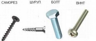
Threaded fasteners are one of the most popular for attaching parts, assembling products, equipment, and structures. There is no industry where it is not used. There are many thread characteristics: pitch, tolerance range, number of starts, nominal diameter, profile type and others. One of these is units of measurement, inches or millimeters.
There is often a situation when it is necessary to replace a bolt, pin or screw, but the fastener purchased for maximum similarity “by eye” is not screwed into the mounting hole. One of the reasons is an attempt to screw a fastener with an external inch thread into a hole with a metric thread. Or vice versa. This situation often arises when replacing fasteners on products or equipment manufactured in the UK, USA, Japan, or Australia. There, inch threads have priority.
How to distinguish an inch thread from a metric thread? There are two main ways - by measuring the pitch and diameter or using a special tool.
Measurement
Fastener thread markings are done differently in metric and inch systems. In metric, this is an indication of the thread pitch (the distance between adjacent threads) in millimeters, while in inch it is the number of threads per inch.
Determining the type and size of fastener thread comes down to the following operations. Use a caliper to measure the diameter. Then, using an inch ruler or caliper, measure the number of threads in one inch and the thread pitch. You can also use a regular ruler with measured 2.54 mm (1 inch = 2.54 mm). The metric thread pitch on small fasteners can be found by measuring the distance between 10 turns and dividing the resulting value by 10. The resulting values should be compared with the table below. The maximum match in diameter, number of turns, pitch indicates the size and type of thread. It should be noted that there are many different types of inch threads. The table shows the most common ones in the diameter range from 8 mm to 64 mm.
You can also use a thread gauge to measure threads. This is its direct purpose. A thread gauge is a set of plates with protruding teeth for a specific thread, united on a single axis. The thread size is engraved or permanently inked on the plate itself. Checking the thread is done by applying plates that are closest in size to the thread. If there is a complete match, without gaps, the thread can be considered defined, and its size can be viewed on the thread gauge plate. Thread gauges are produced separately for metric, inch threads or both types.
Linear dimensions measurements
How to measure linear dimensions using a caliper? It all depends on the material of the part/workpiece. For rigid elements, the product is pressed tightly against some support plate, after which the measurement is taken with the external measuring jaws of the tool. You must first determine the suitability of the existing type of caliper for use. For example, the main measuring scale on the rod should be less than 25...30 mm longer than the part (taking into account the own width of the jaws). When using a depth gauge, this value is even smaller, since the length of the frame should also be taken into account (for the most common tools 0-150 mm and an accuracy of 0.05 to 0.1 mm, this parameter is taken to be at least 50 mm).
How to measure the cross-section of a wire with a caliper? Non-metallic products are flexible, and therefore significantly distort the result obtained in the usual way. Therefore, a rigid steel part (screw, nail, piece of rod) should be inserted into the cambric, and then the cross-sectional diameter of the wire should be determined using external jaws. Do the same if you need to find out the internal size of the wire.
Wire diameter measurement
The question - how to measure a chain with a caliper - is often asked by cyclists, since chain wear, defined as the distance between its adjacent links, makes it possible to decide whether to replace the product. The outer jaws are set at a distance of 119 mm and inserted into the link, after which they are stretched to the sides until further increase in size is impossible (to facilitate the work, the chain can be pre-loaded with a tensile force). The deviation from the original size will show actual wear, which must then be compared with the maximum allowable.
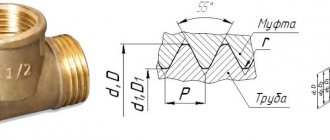
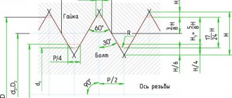
Metric thread. Profile.
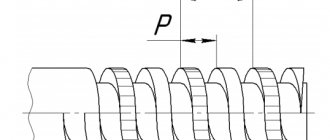
Metric thread profile according to GOST 9150 (ST SEV 180)
The nominal thread profile and the dimensions of its elements must correspond to those indicated in the figure and table.
d is the outer diameter of the external thread (bolt); D—outer diameter of the internal thread (nut); d2 is the average diameter of the bolt; D2 - average diameter of the nut; d1 - internal diameter of the bolt; D1 - internal diameter of the nut; P - thread pitch; H is the height of the original triangle; R is the nominal radius of curvature of the bolt root; H1 - working height of the profile.
Notes:
- The shape of the bolt thread root is not regulated and can be either rounded or flat-cut. A rounded cavity shape is preferred.
- The shape of the nut thread root is not regulated.
The table shows the dimensions of the thread profile elements. The shape of the screw thread cavities is not regulated by the standard; rounding of the depressions (with radius R) reduces stress concentration and increases the strength of the screw under cyclic loading.
According to GOST 24705 (ST SEV 182), the thread is metric, the main values of thread diameters are determined by the formulas:
where d3 is the internal diameter of the bolt.
Connecting thin-walled parts
If it is necessary to connect thin-walled parts, then it will not be possible to directly use a threaded connection: the number of turns may be too small to reliably hold the fastener within the thickness of the part. In such cases, a flange connection is used. In this case, the edge of the part adjacent to the joint is strengthened by special stamping or welding of a flange - a thickening in which holes are made and threads are cut. If the configuration of the product allows, then sometimes instead of a full flange, only nuts are welded at the fastening points.
Flange connection
If the parts to be connected are cylinders of the same diameter and thickness, there is another method: an internal thread is cut on one cylindrical surface, and an external thread of the same nominal diameter is cut on the other. Next, the parts are screwed onto each other. This connection method does not require the application of large forces to the fastening point and is used for lightly loaded structures, such as, for example, cylindrical instrument casings.
Rectangular thread
Table 3 presents data on rectangular threads.
Rectangular threads are most often made with a square tooth profile. But some manufacturers use rectangular profiles with an extended flange of the horizontal part for reinforcement
Table 3: Thread dimensions and helix pitch
| Nominal thread diameter d, mm | Step P | |||||
| 1 row (preferred) | Row 2 (permissible) | large | small 1 | small 2 | small 3 | small 4 |
| 8 | 2,00 | 1,50 | 1,25 | |||
| 9 | 2,00 | 1,50 | ||||
| 10 | 2,00 | 1,50 | 1,25 | |||
| 11 | 3,00 | 2,00 | 1,25 | 1,00 | ||
| 12 | 3,00 | 2,00 | 1,50 | |||
| 14 | 3,00 | 2,00 | ||||
| 16 | 4,00 | 2,00 | 1,50 | 1,00 | 0,75 | |
| 18 | 4,00 | 2,00 | ||||
| 20 | 4,00 | 3,00 | 2,00 | |||
| 22 | 8,00 | 5,00 | 4,00 | 3,00 | 2,00 | |
| 24 | 8,00 | 5,00 | 4,00 | 3,00 | 2,00 | |
| 26 | 8,00 | 5,00 | 4,00 | 3,00 | 2,00 | |
| 28 | 8,00 | 5,00 | 4,00 | 3,00 | 2,00 | |
| 30 | 10,00 | 6,00 | 3,00 | |||
| 32 | 10,00 | 6,00 | 3,00 | 2,00 | ||
| 34 | 10,00 | 6,00 | 3,00 | |||
| 36 | 10,00 | 6,00 | 3,00 | 2,00 | 1,50 | |
| 38 | 10 | 7 | 6,00 | 5,00 | 3,00 | |
| 40 | 10 | 7 | 6,00 | 5,00 | 3,00 | |
| 42 | 10 | 7 | 6,00 | 5,00 |
Inch threads
Applied to bolts and other parts made in the UK and USA. Until recently, they were very popular in the aircraft industry (the gradual transition to metric began only recently).
Helix dimensions and pitch
| d, ʺ | d, mm | P, mm | Number of threads per 1 ʺ | ||||||
| execution | |||||||||
| normal | small | normal | small | ||||||
| I | II | III | I | II | III | ||||
| 1/16 “ | 1,588 | 0,706 | 0,529 | 0,470 | 0,397 | 36 | 48 | 54 | 64 |
| 1/8 “ | 3,175 | 0,706 | 0,529 | 0,470 | 0,353 | 36 | 48 | 54 | 72 |
| 3/16 “ | 4,763 | 1,058 | 0,706 | 0,529 | 0,470 | 24 | 36 | 48 | 54 |
| 1/4 “ | 6,350 | 1,270 | 1,058 | 0,847 | 0,706 | 20 | 24 | 30 | 36 |
| 5/16 “ | 7,938 | 1,411 | 1,270 | 1,058 | 0,847 | 18 | 20 | 24 | 30 |
| 3/8 “ | 9,525 | 1,588 | 1,411 | 1,270 | 1,058 | 16 | 18 | 20 | 24 |
| 7/16 “ | 11,113 | 1,814 | 1,588 | 1,411 | 1,270 | 14 | 16 | 18 | 20 |
| 1/2 “ | 12,700 | 2,117 | 1,814 | 1,588 | 1,270 | 12 | 14 | 16 | 20 |
| 9/16 “ | 14,288 | 2,117 | 1,814 | 1,411 | 1,058 | 12 | 14 | 18 | 24 |
| 5/8 “ | 15,875 | 2,309 | 2,117 | 1,814 | 1,588 | 11 | 12 | 14 | 16 |
| 3/4 “ | 19,050 | 2,540 | 2,117 | 1,588 | 1,270 | 10 | 12 | 16 | 20 |
| 7/8 “ | 22,225 | 2,822 | 2,540 | 2,117 | 1,588 | 9 | 10 | 12 | 16 |
| 1 “ | 25,400 | 3,175 | 2,540 | 1,588 | 1,411 | 8 | 10 | 16 | 18 |
| 1 1/8 “ | 28,575 | 3,629 | 3,175 | 2,540 | 2,117 | 7 | 8 | 10 | 12 |
| 1 1/4 “ | 31,750 | 3,629 | 3,175 | 2,822 | 2,540 | 7 | 8 | 9 | 10 |
| 1 3/8 “ | 34,925 | 4,233 | 3,175 | 2,540 | 2,117 | 6 | 8 | 10 | 12 |
| 1 1/2 “ | 38,100 | 4,233 | 2,822 | 2,117 | 1,588 | 6 | 9 | 12 | 16 |
| 1 5/8 “ | 41,275 | 5,080 | 4,233 | 3,175 | 2,540 | 5 | 6 | 8 | 10 |
| 1 3/4 “ | 44,450 | 5,080 | 4,233 | 2,540 | 2,117 | 5 | 6 | 10 | 12 |
| 1 7/8 “ | 47,625 | 5,080 | 4,233 | 3,629 | 3,175 | 5 | 6 | 7 | 8 |
| 2 “ | 50,800 | 5,080 | 3,175 | 2,540 | 2,117 | 5 | 8 | 10 | 12 |
| 2 1/4 “ | 57,150 | 5,080 | 3,175 | 2,540 | 2,117 | 5 | 8 | 10 | 12 |
| 2 1/2 “ | 63,500 | 6,350 | 5,080 | 4,233 | 3,175 | 4 | 5 | 6 | 8 |
| 2 3/4 “ | 69,850 | 6,350 | 5,080 | 4,233 | 3,175 | 4 | 5 | 6 | 8 |
| 3 “ | 76,200 | 8,467 | 6,350 | 4,233 | 2,540 | 3 | 4 | 6 | 10 |
When measuring thread pitch in inches, what is more important is not the specific distance between the threads, but the overall number of threads. The P parameter is essentially a test parameter, and you need to find the number of grooves at a distance of 1 ʺ. The reverse calculation is even simpler: you just need to divide 25.4 by the number of notches.