Design and principle of operation of theodolite
The basis of the theodolite is a telescope that rotates in horizontal and vertical planes. The pipe is connected to a microscope, with the help of which you can obtain the values of the angles marked on the dial, and when using a special rangefinder rod, it is also possible to determine the distance between points as when → working with a level (how to work with a level is described in the link).
The principle of theodolite surveying is to obtain unknown values of the coordinates and heights of the required point, based on points with known values.
Before starting the survey, the theodolite must be brought into working position. The instrument is installed on a tripod above a point with known coordinates and is brought to a horizontal position with special screws located on the stand (1). Through the eyepiece (2) we see the center of the sighted point over which we install the instrument, and the levels (3) help us control the horizontal position of the instrument. By working with the clamping screws of the tripod and stand, we achieve a position where the instrument is installed horizontally above the starting point. For beginners, this procedure causes some difficulties, but experts center the theodolite in less than a minute. In high-precision instruments, the centering system is optical; in others, a plumb line on a thread is used.
Next, use the sight (8) to roughly aim at the target, and with the screws (4,7) we smoothly move the reticle to the center of the object being photographed, controlling the process with the help of a telescope (9). Since the instrument is optical, it is impossible to take a reading in the dark. To work, we will need to adjust the mirror (10) so that as much light as possible enters the system. After sighting the target, we take a reading using the microscope eyepiece (11).
I recommend: Question: How to raise the gate opening in an underground garage?
Theodolites verification
Before carrying out verifications, it is necessary to conduct a general inspection of the theodolite:
a) the optical system of the telescope must be clean and give a clear image;
b) rotation of the device should be easy and smooth;
c) lifting, securing, guiding screws must be in good working order;
d) the reading systems must be clearly and clearly visible through the microscope.
After a general inspection of the theodolite, it is checked:
1. Checking the rotation of the lifting screws. They should rotate easily and smoothly.
2. The axis of the cylindrical level when alidating a horizontal circle must be perpendicular to the vertical axis of the device. To do this, when alidating a horizontal circle, the level is brought to the zero point using lifting screws. Rotate the device 180°; if the level bubble deviates from the zero point by more than one division, then its position is corrected with a correction screw by ? deviations.
3. The vertical stroke of the grid of threads should lie in the collimation
telescope plane. To do this, place a vertical stroke of the thread grid at a clearly visible point. The pointing device rotates the telescope around a horizontal axis. If the point moves from the vertical axis, then loosen the reticle adjustment screws and turn the eyepiece along with the reticle. The verification is repeated.
4. The sighting axis of the telescope must be perpendicular to the axis of rotation of the telescope. Deviation from the perpendicular direction causes a collimation error "c". Usually the value measured is 2s. To do this, point the telescope at a distant object and take readings at CL1 and CP1. The theodolite is rotated 180°, pointed at the same object and readings are taken at CL2 and CP2.
2c is calculated using the formula 2c=/2.
2c should be less than triple the angle measurement accuracy. To eliminate the collimation error, set a reading calculated using the formula KL=KL2-s or KP=KP2+s. Adjust the mesh of threads until it aligns with the object. The verification is repeated.
5. The axis of rotation of the telescope must be perpendicular to the vertical axis of rotation of the theodolite. Select a clearly visible point at a height of 40° and at the height of the device. The telescope is moved through the zenith and pointed at the same point. If the points marked below coincide, then the tilt of the pipe is acceptable; if not, then the perpendicularity of the axes is corrected only in workshops.
6. The zero point (MO) of the vertical circle should be constant and close to 0°. MO—counting along a vertical circle with the horizontal position of the sighting axis of the telescope and with the position of the level bubble with the alidade of the horizontal circle at the zero point. To determine MO, sight at two positions of the vertical circle at the selected point and take readings. For the 2T30P device, MO is calculated using the formula MO = (KL + KP)/2. MO is determined by sighting on various targets 3-4 times. The arithmetic mean of all measurements is taken as the final value. The discrepancy between MO values should not exceed triple the accuracy of the theodolite. The correctness of the MO calculation is checked by calculating n using the formulas n = KL-MO;
n=KP-MO, n=0.5(KL-KP). The values n must be equal.
Rice. 10. Theodolite 2T30P device: 1-crack screw; 2- fixing screw of the telescope; 3- optical sight; 4- column; 5- fixing screw of the horizontal circle (limbo); 6- horizontal circle; 7- adjustment screw; 8- alidade fixing screw; 9- cylindrical level for alidade; 10 - horizontal circle guide screw; 11- microscope eyepiece; 12- illumination mirror; 13- side column; 14-groove, for reference compass; 15 - vertical circle; 16-adjusting nut; 17 - telescope of the device; 18 diopter eyepiece ring; 19- telescope guiding screw; 20- alidade guide screw; 21- triangular stand; 22-lifting screws; 23- bushing; 24- base; 25- cover.
Taking readings with a theodolite
A countdown is a number consisting of degrees, minutes and seconds (not always seconds). Looking through the microscope, we will see the upper and lower scales, marked, respectively, for taking readings along a vertical and horizontal circle.
There is a scale microscope and an evaluator microscope (line microscope). The evaluator microscope immediately shows the required angle along the horizontal and vertical axes in degrees and minutes, although the accuracy is slightly lower than that of a scale microscope, since the minimum division is 10 minutes, and with an accuracy of up to a minute you have to determine it by eye.
Evaluating microscope (left) and theodolite scale microscope
There are 2 scales that change their position in relation to each other - the limb scale and the alidade scale. In a scale microscope, the alidade scale is marked with numbers from 1 to 6 and 60 divisions, corresponding to 60 minutes. The alidade scale is movable.
In a scale microscope, the value of degrees will be the number that falls on the alidade scale for a horizontal angle or, accordingly, a vertical one. The value in minutes will be the number indicated by the degrees of the dial on the alidade scale. For example, in the picture below we will see the values of the horizontal and vertical angles, respectively, 181 degrees 43 minutes and 121 degrees 2 minutes
Accuracy of readings
Over time, the bearings in the device can wear out, which negatively affects the obtained values. To do this, the reading is taken several times, at different values of the circle (limbe) of the microscope.
To eliminate collimation errors, the telescope is moved through the zenith, the theodolite is rotated 180 degrees and readings are taken again. From several values, an arithmetic mean is obtained, which will be the correct value of the measured angle. If the readings differ significantly (more than a minute), the procedure should be repeated.
In addition to the method of translation through the zenith, there is a method of half-steps, when the dial is shifted by an integer value of the angle of degrees and the count is taken a second time. To rearrange the dial, there are screws (5, 6). For example, the horizontal angle value is 358 degrees 45 minutes. After taking the reading, use screw (6) to shift the starting point of the dial by an integer value of degrees of angle (for convenience), securing it with screw (5). For example, by moving the dial by 90°, we should get an angle value in a horizontal circle of 358°45′ + 90° = 88°45′.
Check and adjustment
Before starting work, most measuring instruments must be calibrated and ensure that it works correctly and that the measured geometric quantities do not exceed the established errors. This procedure is called verification. If, after its completion, it is discovered that the device is not working correctly, it is necessary to perform an adjustment - that is, using screws or keys, correctly set the “zero” readings of the device.
For correct operation of the theodolite, during first operation you should make sure that:
- The main vertical of the device is located parallel to the column-shaped supports and perpendicular to the horizontal measuring circle and alidade;
- The threads in the optical mesh of the tube respectively coincide with the horizontal (determined by horizontal circular rotation with focus on a distant point) and vertical (determined by a remote plumb line on the thread);
- The sighting axes in the tube lenses coincide and form an exact perpendicular to the horizontal axis of the alidade - that is, if the tube is turned 180 degrees, the sighting axis will not shift either to the left or to the right from the base value;
- The axis on which the tube itself is attached has no distortions in height and is perpendicular to the main vertical axis of the theodolite device;
- The horizontal axes on both lenses must be parallel.
In modern devices, the body of which is sealed, the company that manufactured the device is responsible for compliance with these indicators. If discrepancies are observed in any of the verification points, you should contact a specialized workshop or a representative of the manufacturer.
About verification “relatively” briefly, you can watch the video:
Determining the height of a building with a theodolite (+ video)
For example, consider the formula for determining the height of a building, structure, pole, etc. We take the readings of the values indicated in the figure below with a theodolite and a measuring tape and write them down in a table (notebook).
The theodolite is placed at a distance no less than the height of the building; if this is not possible, then as far as possible from the object. Next, according to the formula h = h1 + h2 = d(tgv1 + tgv2)
calculate the height of the building.
I recommend: How to work as a level
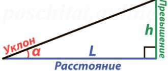
If line AB has a slope on the ground, it is necessary to calculate the horizontal location of this line, its projection onto the horizontal plane using the formula d = Scosν
taking readings as shown in the figure below.
Horizontal line layout
This video will tell you how to determine the height of a structure, with calculations and formulas.
Correct operation
Regardless of which model of theodolite – electronic or classical – you are going to use, it is important to remember that this is a sensitive, high-precision device that requires careful handling and correct operation.
It should be transported from point to point in a special box or case designed for a specific model, trying to prevent the device from shaking or falling from a height.
Mechanical parts of the structure must move freely when rotating on axes or screws, but should not be loose and, if necessary, tightly fixed during operation of the device.
It is also recommended to always carefully monitor the optical components - eyepieces and sights must be protected from dust and dirt, and not allowed to deform (chips, cracks, etc.)
Special attention is paid to the tripod - when placing it, you should make sure that the tripod is positioned stable and that all legs and the platform are firmly fixed.
During measurements, work with the device must be quite careful, after which it must be checked and cleaned before packing it in a box or case.
Measuring a horizontal angle with a theodolite (+ video)
To measure a horizontal angle with a theodolite, you need to install the theodolite in one of the corners of the triangle. Determine right and left direction. Where the zero will be located on the scale is not important, we can get the angle value as the difference in the readings of two points. Aim at the first point and take a reading. Using one of the methods above to check the value, take the reading a second time and calculate the average value; if the discrepancy is no more than 1 minute, then the measurements were made correctly. We record in a journal (notebook). Next, we aim at the second point, and also take a reference. If the value of the right angle is less than the left, you need to add 360 degrees to it. The difference in readings will be our angle.
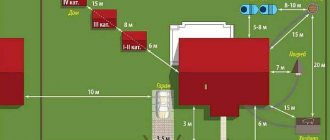
Polar method of surveying with theodolite
In construction, two surveying methods are mainly used - polar (Fig. 1) and the method of alignments and perpendiculars (Fig. 2). Other methods of surveying with a theodolite: the method of corner intersections, linear intersections, the method of auxiliary alignments and the bypass method.
With the polar method
we start from two points with known values. These points can be taken from an existing project, plan, state geodetic network (if there is an SRO), or when independently developing a plan, you can set these points yourself, starting from a self-defined zero along x;y;z coordinates. The polar method can be closed or open.
Let's first consider the open-loop method, which we will then lead to the closed one. The tool is set to origin point 2, the initial reference is taken to origin point 1, or vice versa. The distance is measured with a tape measure, measuring tape or rangefinder to theodolite traverse point 1, and a mark is installed (a peg flush with the ground, or a vertical rod). The left-hand angle to theodolite traverse point 1 is measured. Having reached survey point 2, we sequentially calculate the values of the horizontal angles to each of the contour points (Fig. 1). In this way, you can also measure the distances to the points of the object being photographed and vertical angles from any point of the theodolite traverse you need. Next, using formulas to calculate the required values and distances, many calculations are given in several videos on this page.
The last stage is “linking” the theodolite traverse to known points and creating → a terrain plan on paper (the link tells how to make a plan or diagram of the terrain). Since the control points are in the same coordinate system, this polygon can be made closed by moving from control point 2 to the starting point 1. Next, you need to calculate the error of a closed theodolite traverse, which is calculated more easily than for an open one.
I recommend: How to distinguish the type of rubble stone by appearance
Error of closed theodolite traverse, discrepancy
As a result of simple calculations, we obtain a discrepancy, which we compare with the acceptable one. If the value is within tolerance, the error spreads proportionally to the sides of the polygon.
For a closed theodolite traverse, the error is determined by the formula:
Where is the actual (measured) sum of angles, and is the theoretical sum of angles, that is, which should be according to the laws of geometry.
The theoretical sum of angles is calculated using the formula:
Where n is the number of measured angles.
The permissible error of the sum of the angles of a closed theodolite traverse is determined by the formula:
If the actual error is greater than the permissible one, we check the records again; if this is not the problem, we take the readings again. If the error is less than or equal to the permissible one, we calculate the correction using the formula:
The value is spread across all angles. If the number is not an integer, we introduce corrections to some angles more than to others.
Surveying with theodolite using the alignment and perpendicular method
The method of alignments and perpendiculars is well suited for marking work. In this case, we plot right angles on the ground, sequentially moving the tool to the obtained points on the ground. For example, from the base side 1-2 we get control direction 1. The mesh of threads in this case plays the role of laces. Having measured the required distance, we find ourselves at the starting alignment point, and then we work according to the diagram.
You can use a theodolite to break up a rectangular polygon or check the alignment of the broken polygon. The theoretical sum of angles in a closed loop should be 360°. By placing the tool sequentially at each point of the object, we measure the internal angles. For example, a discrepancy of 1° on a 10-meter segment is approximately 20 cm. So, you can evaluate the tolerances depending on the class of the structure, and, if necessary, make adjustments to the alignment of the axes.
How to correctly measure vertical and horizontal angles
Measuring horizontal angles using a theodolite takes place in two or three stages, depending on the type of device. If a classic theodolite is used, one computational one will be added to the two measuring ones.
Assuming that the vertex of the desired angle is the installed device, the operator points the vertical thread of the telescope reticle at the first mark and fixes the value on the horizontal limb. In modern theodolites with electronic “stuffing”, the mark is determined on the dial automatically and fixed as 0 using buttons on the instrument panel; in traditional ones, it is noted by the operator through the eyepiece of the reading device and entered into the measurement log.
After this, the tube is aimed clockwise at the second mark. The electronic device will calculate the angle itself and display the readings on the screen. When working with a traditional device, the operator will have to take readings from the horizontal limb through a microscope and, through geometric operations, calculate the value of the desired angle.
You can see more clearly how to measure horizontal angles in the video:
Vertical angles are measured in the same way. In this case, the rotation of the tube will be carried out not in the horizontal plane, but in the plane of the vertical limb, with the marks aligned not with the vertical, but with the horizontal thread of the tube mesh.
How to work with a theodolite, educational instruction for beginners:
Determining distance with a theodolite using a rangefinder rod
Using a theodolite, you can determine the distance to the point of taking readings, with an error of approximately 10 cm. We install the rangefinder rod at the point to which we want to measure the distance. The theodolite's reticle has 2 rangefinder lines located at the top and bottom. Measuring distance is simple. We count the number of centimeters from one horizontal rangefinder line to another and multiply the resulting value by the rangefinder coefficient of the pipe, which is usually equal to 100.
Determining distance with a theodolite using a rangefinder rod along rangefinder threads
In the example given, the distance to the batten will be approximately 19.4 meters.
What is the difference between a level and a theodolite
The main difference is that the level is simpler in design than a theodolite, but an assistant is needed to work with it when performing calculations. In the basic configuration, the device also consists of a tube mounted on a tripod, but, unlike a theodolite, the level has only one horizontal plane of rotation.
It is along it that the operator orients the mesh of the instrument tube while taking measurements. In this case, the difference in heights is recorded using a marked rod, which is held vertically by an assistant at the measurement point.