In most cases, grinding machines and center machining machines are used. Where grinding is performed using an abrasive cylinder rotating at high speed. However, in addition to this, there are machines that do not have a single axis of rotation, and the material is processed using several rotating cylinders. But what exactly is centerless grinding? How to work correctly with such a processing machine?
What is centerless grinding
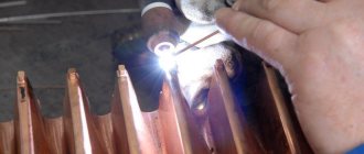
With central grinding, material processing is carried out using a metal cylinder with abrasive, which rotates at high speed around its axis. The part is fixed using special clamps and brought to the operating machine. Upon contact, the abrasive cuts off a thin layer from the surface, which provides grinding. Centerless machining technology:
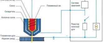
- A centerless grinding machine consists of not one, but two abrasive wheels. One circle (guide) rotates around its axis quite slowly (speed is about 10-20 meters per minute), but the other circle (processing) rotates very quickly (about 30-40 meters per minute). If necessary, the rotation speed can be adjusted manually using special knobs and sensors.
- Additionally, the machine is equipped with a special supporting surface under the rotation wheels, which can move in one direction perpendicular to the plane of rotation of the abrasive wheels. This surface is used to support the part during grinding work.
- To carry out grinding work, the engineer places the part on a supporting surface and brings it to the guide machine. Then the following happens: a slow guide wheel ensures rotation of the part, and a fast processing wheel grinds off all roughness and unevenness from the surface.
During processing, the axis of rotation of the part is actually located above both abrasive wheels, which is why this technology is called centerless.
General concept of grinding
- In primitive cases, use hard granular sand or harder emery, pour it onto a hard surface and rub the object being processed against it. The angular grains, rolling between both surfaces, produce a large number of impacts, from which the protruding places of these surfaces are gradually destroyed, and the grinding grains themselves are rounded and disintegrated into pieces. If one of the surfaces is soft, the grains are pressed into it, remain motionless, and produce a series of parallel scratches on the second surface; in the first case, a matte surface is obtained, covered with uniform pits, and in the second, a so-called “stroke” gives the surface a shine that turns into polishing, when the stroke is so small that it becomes invisible to the eye. So, when grinding two copper plates against each other with emery, both will turn out matte, and the same emery, being glued to the surface of the paper, will impart shine when rubbed against the brass surface.
- Fragile, hard glass wears off more than a soft and elastic metal plate, and diamond powder can wear off the surface of the diamond itself, and pieces of quartz can be processed on a sandstone sharpener. The pits produced by the grains of emery are smaller, the finer the grains themselves; Therefore, grinding can produce the most precisely machined surfaces, as is done when grinding optical glasses.
This is interesting: Hole processing: types of operations and tools used
Features of the technology
The adhesion of the part to the surface of the leading abrasive wheel is ensured by its rotation, and the higher the rotation speed, the more reliable and stable the adhesion will be. A working machine has one characteristic feature - the lower the axial rotation speed of the guide element, the better the cutting abrasive wheel will work (that is, the cutting force is inversely proportional to the rotation speed of the guide element). Therefore, in most cases, vulcanization or some other rubber coating is applied to the guide wheel to further increase the adhesion force of the part.
Centerless grinding is widely used in large modern enterprises where the production and processing of parts is carried out in large batches. This technique is mainly used for machining external surfaces only, although if necessary it can be adapted for turning some through and internal holes. Centerless grinding of external surfaces has many advantages:
- The technique significantly reduces the time for processing one part. This allows you to speed up production and save on energy costs.
- The combination of the previous factors ultimately leads to a reduction in production costs, which has a beneficial effect on the competitiveness of the company's products in the market.
- The technology is simple; the master will master the technology almost from the first approach to the machine.
- The rotation of the guide element reliably stabilizes the workpiece, so grinding is very high quality and precise.
- The machines do not require special care or adjustment; The rubber coating on the guide element lasts quite a long time, and if necessary, it can be quickly replaced.
Centerless cylindrical grinding machine 3M182
| Parameter name | 3M182 | — |
| Main settings | ||
| The largest guaranteed diameter of the installed product, mm | 25 | |
| The largest permissible diameter of the installed product, mm | 35 | |
| Minimum diameter of the installed product, mm | 0.8 | |
| Smallest diameter recommended for plunge grinding | 2,5 | |
| Maximum length of processed products (limited by the rigidity and stability of the products) during through grinding, mm | 170 | |
| Maximum length of processed products (limited by the rigidity and stability of the products) during plunge-cut grinding, mm | 95 | |
| Height from the base of the machine to the axis of the circles, mm | 1060 | |
| Height from the bridge mirror to the axis of the circles, mm | 160 | |
| Grinding wheel | ||
| Maximum outer diameter, mm | 350 | |
| Smallest outer diameter, mm | 280 | |
| Maximum height, mm | 100 | |
| Hole diameter, mm | 203 | |
| RPM | 1910 | |
| Peripheral speed, m/sec | Up to 35 | |
| Leading Circle | ||
| Maximum outer diameter, mm | 250 | |
| Smallest outer diameter, mm | 200 | |
| Maximum height, mm | 100 | |
| Hole diameter, mm | 127 | |
| Maximum angle of inclination in the vertical plane, degrees | ±5 | |
| Maximum tilt angle in the horizontal plane, min | ±30 | |
| RPM during operation (stepless regulation) | 17—150 | |
| Number of revolutions per minute when straightening | 300 | |
| Grinding head | ||
| Grinding wheel spindle end size according to GOST 2323-67, mm | 80 | |
| Maximum installation movement, mm | 90 | |
| The greatest accelerated movement during plunge-cut grinding, mm | 20 | |
| Working movement per one division of the feed mechanism dial, mm | 0,001 | |
| Working movement per one revolution of the feed mechanism dial, mm | 0,08 | |
| Working movement of jog feed from the handle, mm | 0,001 | |
| Working displacement by plunge mechanism, mm | Up to 0.95 | |
| Feed rate during plunge-cut grinding is the highest, mm/min | 10 | |
| Feed rate for plunge-cut grinding is the lowest, mm/min | 0,06 | |
| Grandmother | ||
| Maximum displacement, mm | 80 | |
| Movement of the feed screw dial by one division, mm | 0,05 | |
| Movement of the feed rate dial per revolution, mm | 6 | |
| Wheel dressing mechanism | ||
| Transverse movement of diamond per dial division, mm | 0,01 | |
| Transverse movement of the diamond per one revolution of the dial, mm | 1,5 | |
| Maximum speed of diamond movement in the longitudinal direction, mm/min | 250 | |
| The speed of diamond movement in the longitudinal direction is the lowest, mm/min | 30 | |
| Maximum rotation angle of the copier, gra | ±2 | |
| Caliper | ||
| Maximum adjustment movement of the caliper knife in height, mm | 10 | |
| Hydraulic drive of the plunge mechanism | ||
| Pump capacity, l/min | 12/8 (double) | |
| Nominal pressure, kgf/cm2 | 10 | |
| Hydraulic tank capacity, l | 100 | |
| Lubrication unit | ||
| Capacity of the grinding wheel head spindle bearing lubrication pump, l/min | 5 | |
| Capacity of the spindle headstock bearing lubrication pump, l/min | 1,6 | |
| Grinding wheel bearing tank capacity, l | 65 | |
| Capacity of the drive wheel bearing tank, l | 15 | |
| Cooling unit | ||
| Pump capacity, l/min | 45 | |
| Magnetic separator throughput, l/min | 50 | |
| Capacity, tank, l | 120 | |
| Drive, dimensions and weight of the machine | ||
| Type of supply current | AC three-phase, current frequency 50Hz | |
| Supply voltage, V | 380 | |
| Electric drive voltage, V | 380 | |
| Control circuit voltage, V | 110 | |
| Voltage of local lighting circuits, V | 36 | |
| Signaling voltage, V | 5,5 | |
| DC voltage, V | 110 | |
| Grinding wheel drive motor - type | AO2-51-4-S1 | |
| Grinding wheel drive electric motor - power, kW, | 7,5 | |
| Grinding Wheel Drive Motor - RPM | 1460 | |
| Drive circle drive motor - type | PBST-22-V | |
| Drive circle drive electric motor - power, kW | 0,85 | |
| Drive Circle Drive Motor - RPM | 2200 | |
| Electric motor for driving an electric machine amplifier - type | EMU-12A-S1 | |
| Electric motor for driving an electric machine amplifier - power, kW | 1,2 | |
| Electric machine amplifier drive motor - rpm | 2900 | |
| Hydraulic pump drive electric motor - type | AOL2-21-4-S1 | |
| Hydraulic pump drive electric motor - power, kW | 1,1 | |
| Hydraulic pump drive motor - rpm | 1400 | |
| Grinding wheel spindle bearing lubrication pump drive motor - type | AOL21-4-S1 | |
| Electric motor drive of the grinding wheel spindle bearing lubrication pump - power, kW | 0,27 | |
| grinding wheel spindle bearing lubrication pump drive - rpm | 1400 | |
| Electric motor drive for lubrication pump of drive wheel spindle bearings - type | AOL11-4-S1 | |
| Electric motor driving the drive wheel spindle bearing lubrication pump - power, kW | 0,12 | |
| driving wheel spindle bearing lubrication pump drive - rpm | 1400 | |
| Cooling pump drive motor - type | PA-45-S1 | |
| Cooling pump drive electric motor - power, kW | 0,15 | |
| Coolant Pump Motor - RPM | 2800 | |
| Magnetic separator drive motor - type | AOL11-4-S1 | |
| Magnetic drive electric motor - power, kW | 0,12 | |
| Magnetic drive motor - rpm | 1400 | |
| Grinding wheel dressing drive electric motor - type | PL-062-S1 | |
| Grinding wheel dressing drive electric motor - power, kW | 0,09 | |
| Grinding wheel dressing drive motor - rpm | 1440 | |
| Drive wheel dressing drive electric motor - type | PL-062-S1 | |
| Drive wheel dressing drive electric motor - power, kW | 0,09 | |
| Drive Wheel Dressing Motor - RPM | 1440 | |
| Electric motor for driving rapid movement of the grinding headstock - type | AOL12-4-S1 | |
| Electric motor for driving the accelerated movement of the grinding head - power, kW | 0,18 | |
| Grinding headstock rapid movement motor - rpm | 1400 | |
| Total power of electric motors, kW | 11,67 | |
| Machine dimensions (length X width X height), mm | 2230 x 1455 x 2120 | |
| Weight of the machine with attached equipment, kg | 3470 |
Moscow, Mechanical Engineering. Encyclopedia 2002. Edited by K.V. Frolova
Types of centerless grinding
There are two main methods - with longitudinal and transverse feed. Below we will briefly look at both methods.
Centerless machining with longitudinal feed
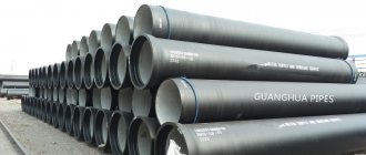
This processing technology is suitable for parts with a constant diameter over the entire surface (pipes, bolt blanks, uniform rods, etc.). During operation of the machine, the part, in addition to stabilizing rotation, can move in the longitudinal direction, which helps the master to better control the grinding. The rotating cylinders are not located parallel to each other, but at a slight angle.
Therefore, when the abrasive wheels rotate, the part can carry out longitudinal advancement of the material, and the greater the angle of inclination, the higher the speed of movement (the operator can change the angle of inclination manually). You need to choose the angle of inclination depending on several parameters - the total length of the part, its diameter, the quality of processing, and so on. Recommendation standards:
- Small workpieces of medium thickness - from 1 to 2.5 degrees.
- Long parts of medium and large thickness - from 1.5 to 3.5 degrees.
- Very small workpieces of any diameter - from 3 to 4.5 degrees.
Please note that these standards apply only to rough grinding - when finishing, the angle of inclination must be reduced by 20-30% to obtain a smooth, uniform surface. Longitudinal grinding should be carried out in several passes. During roughing passes, about 0.1-0.2 millimeters of metal is removed from the surface, and during finishing – 0.02-0.05 millimeters (subject to the standards specified above).
Cross feed grinding (plunge)
This technology is used for processing parts that have various protruding parts, recesses or grooves on the surface (objects of complex shape, jagged things, shaped composition products, etc.) that need to be preserved. The product is fed to the grinding shaft by the leading element perpendicular to the axis of rotation - this allows you to grind the product not as a whole, but in its individual parts. General instructions for using a centerless grinding machine using plunge-in technology look like this:
- Before starting the device, the drive shaft is removed from the grinding shaft, and then the part to be processed is placed on the supporting structure.
- To prevent the workpiece from moving in the longitudinal direction, it is pressed against the supporting structure using a special stop. The stop itself simultaneously serves as a pushing device.
- A guide shaft operating at low speed is brought to the surface, which transmits the rotation of the part. After this, the workpiece is brought to the grinding wheel using a guide shaft.
- During operation, the operator has the ability to control the depth of processing using a guide wheel.
If necessary, the abrasive wheel can be rotated slightly so that the axis of rotation is not strictly perpendicular, but at a slight angle. This procedure may be necessary when you need to firmly press the workpiece against the stop.
Types of treated surfaces
- screw;
- flat (mold matrices);
- curvilinear;
- cylindrical;
- straight;
- conical;
- holes;
Surface roughness after grinding
Sanding belongs to the category of finishing operations and provides high quality surfaces. One of the qualitative characteristics of a surface is roughness. Depending on this parameter, grinding operations are:
1) Preliminary . It is performed on an untreated surface to remove the outer defective layer, or after rough turning or milling, but before heat treatment. Provides roughness within grade 5 – 7 . 2) Finishing . The operation is performed after pre-treatment, using grinding wheels with a finer grain size. The parts are polished after being heat-treated. Roughness grades 7–9 are obtained . 3) Thin . Used to obtain surfaces of 9–10 class cleanliness . Allowance for processing is minimal. 4) Finishing operation . Otherwise called “nursing.” This is obtaining high-precision dimensions of roughness class 11 - 12 by longitudinal feed of the grinding wheel without allowance for processing. In this case, the elimination of ovality and runout of the treated surfaces is achieved.
Centerless grinding of internal surfaces
If necessary, centerless grinding technology can be adapted to process large concentric holes in workpieces. To carry out such work, the master will additionally need to install three rollers that will guide and press the workpieces with holes against the machine. During operation, the grinding wheel is inserted directly into the hole being processed.
When carrying out work, you need to remember some important rules and restrictions:
- The rollers on the machine must be positioned very accurately, because even if there is a slight deviation, the grinding wheel will either not be able to press against the workpiece, or will cut into it too deeply.
- The surface to be sanded must be exclusively cylindrical in shape, other configurations and shapes are excluded.
- The end part of the part must be located strictly perpendicular to its axis - otherwise damage and deformation of the workpiece may occur. The end of the product, abutting the surface of the support sleeve, must be strictly perpendicular to its axis.
As you can see, the restrictions are quite serious, and it is almost impossible to eliminate or minimize their impact. Therefore, centerless grinding technology is rarely used for working with internal surfaces (although in large-scale in-line production its use may be advisable).
We offer the following types of metal grinding:
- Cylindrical grinding
- Surface grinding
- Centerless grinding
- Gear grinding;
- Thread grinding;
- Grinding.
Leave a request using the form or contact us by phone or e-mail
8 This email address is being protected from spambots. You must have JavaScript enabled to view it.
Cylindrical grinding includes two subtypes of grinding - external grinding and internal grinding .
External cylindrical grinding is grinding work on metal to obtain a cylindrical surface of increased precision. Processing occurs with a radial movement of the grinding wheel cutting into the workpiece. The maximum dimensions of workpieces for external cylindrical grinding are diameter up to 500 mm, length up to 1800 mm.
Internal cylindrical grinding is grinding work to remove allowance inside the cylinder, finishing after boring. The maximum dimensions of workpieces for internal cylindrical grinding are diameter up to 400 mm, length up to 1200 mm.
Surface grinding In this case, the part is mounted on a magnetic plate of a surface grinding machine. This type of processing ensures high flatness and parallelism of surfaces. Dimensions of processed parts – up to 800*400 mm. Processed parts: dies, rings, plates, knives, etc.
Centerless grinding Used in large-scale production for processing internal and external surfaces (bearing races, shafts, etc.). Processing is carried out in two circles located opposite each other. The part is based on a support knife between them.
This is interesting: Cold welding for metal - used correctly
Grinding metal surfaces
There is simply a huge number of different metal processing operations, all of which are characterized by the use of certain equipment and tooling. A common finishing process is the sanding process. It involves removing a small surface layer, due to which a certain roughness and more accurate dimensions are achieved. Let us consider the features of this process in more detail.
Metal grinding
The processing of metal and various alloys using an abrasive material is usually called grinding.
This technology allows you to change the roughness and other parameters of the outer or inner cylindrical, as well as flat surface.
Metal grinding can be carried out using various special equipment. When considering the features of such mechanical processing, you need to pay attention to the following points:
- The grinding process is the final stage of processing, which is carried out to obtain a certain roughness.
- This technology is not used to change sizes over a large range.
- Using modern equipment, the surface can be brought to the required roughness after heat treatment of the metal.
When carrying out the operation in question, a fairly large number of features are taken into account:
- Wheel speed is a parameter that depends on the outer diameter of the abrasive and the capabilities of the machine.
- Speed of movement of the part.
- Depth of cut.
- Possibility of cross feeding.
It is worth noting that today such technology is gradually being replaced by fine turning of metal at high speeds and minimal feed.
Main types of grinding
Grinding of parts can take place using a variety of technologies. The most widespread are the following:
- Circular grinding of metal.
- Changes in the roughness of internal surfaces.
- Gear grinding.
- Centerless technology.
- Sanding flat surfaces.
In addition, classification can be carried out according to the type of material used during processing. To automate the process and reduce labor costs, specialized machines are used. There are also models with a built-in CNC unit, which automates the process and ensures high quality of the resulting surface.