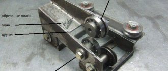
Sheet straightening rollers
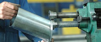
In metal rolling production, as well as in the mechanical engineering sector and in enterprises that manufacture complete parts for various industrial, scientific and medical equipment, sheet straightening rollers are used for straightening sheet metal. These devices have been modernized in accordance with the times to accurately and quickly process sheet-type metal workpieces.
Device of sheet-straightening rollers
Sheet straightening rollers consist of two interconnected mechanisms - the working area and the device drive. The general design of equipment for straightening sheet metal consists of motors, frames and cylindrical rolls, which are placed in a staggered, two-tiered pattern in bearings. The bearings are fixed in the equipment frame.
One of the electric motors of the equipment, equipped with a gearbox, sets the rotational movement of the lower roller part of the drive during the working process. Another electric motor, using a gear mechanism, raises and lowers the upper roller part of the drive device. By design, sheet-leveling rollers are equipped with two special work tables, which are called roller tables.
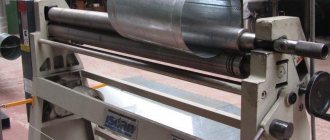
The front roller conveyor serves to feed metal sheets into the rollers, and the rear one ensures support of the product after processing at the exit. Passing a sheet of metal between the rollers, it is straightened by repeated bending. If the condition of the workpiece has large-scale deformation, then the product is passed through the rollers repeatedly.
Operating principle of sheet straightening rollers
When the machine is started, the shafts of the gear cage transmit the guiding movement to the rollers, which carry out the process of straightening the product. The transmitting movement is carried out using articulated spindles.
The articulated spindles in the sheet-straightening roller device are capable, thanks to their unique connection, of turning in all planes. Unlike the upper rollers, which are installed in a mobile traverse, the lower row of rollers has a fixed axis fixed in the racks of the device frame.
The position of the movable traverse is adjusted through the control panel with an indicator device.
A properly organized process of straightening metal sheets using equipment such as sheet-straightening rollers has a significant impact on the efficiency and quality of work carried out with metal. Therefore, to improve and optimize the work process, the equipment is equipped with a centering device that operates on the principle of pneumatic systems. Lifting and removal operations during the operation of straightening rollers are carried out using special sheet stackers with magnetic properties.
Sheet straightening rollers are not cheap equipment. Therefore, to purchase devices, it is necessary to choose only a supplier that has been verified by many positive recommendations and who can ensure delivery of equipment that meets all requirements in the shortest possible time. In addition to delivering the equipment to the area of further stationary operation, it is worth discussing in advance the conditions for installation of the machines and further maintenance for the period specified in the warranty card.
There are certain types of sheet-straightening rollers for different enterprises. They differ in performance levels, sizes and sets of additional equipment. Accordingly, for a private blacksmith shop, you can choose a machine whose cost will be significantly less than the cost of the equipment necessary for large-scale production.
| Processing metal products by galvanic method is one of the most common and popular coating methods. With his help… |
| Today, baling presses for scrap metal processing have fairly high performance and are capable of processing large amounts of scrap, even… |
| Machines for bending reinforcement are an indispensable thing for construction organizations and industrial enterprises. Steel reinforcement is used as the main reinforcing material, and therefore it is very popular in the construction of various engineering structures and buildings... |
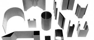
| The initial element from which the entire process on equipment for the production of metal profiles actually begins is the unwinding device. It is on this that it is strengthened... |
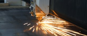
| The operating principle of a correct cutting machine is as follows. Initially, the machine starts, the operation of the machine is carried out by an electric motor. Through clinometer type transmission... |
| The working process of producing a spring on a spring-coiling machine involves the presence of such basic stages as the initial preparation of material for the manufacture of a spring-type product. Then after the material... |
Source: https://promplace.ru/valtci-listopravilnie-709.htm
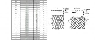
Layer straightening machine design
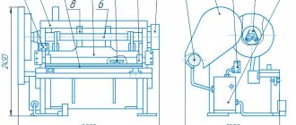
The sheet straightening machine consists of the upper and lower rows of straightening rollers 1, 2, arranged in a checkerboard pattern with the same pitch t, setting and guiding rollers 3, 4, installed in front of and behind the upper row of straightening rollers 1 at a distance less than or equal to 2t from the outermost straightening rollers rollers 1, paired frame rollers 5, installed in front of and behind the lower row of straightening rollers 2 at a distance less than or equal to 2t from the outer straightening rollers 2. The
upper row of straightening rollers 1 is installed on a movable cross-beam 6 with a pressure device 7 and side rotary units 8.
The lower row of straightening rollers 2 is installed permanently on the frame 9, except for the outermost rollers 10, which are installed with the possibility of vertical reciprocating movement from their drive 11.
The drive and guide rollers 3, 4 are each installed on its own lever 12, which is moved, for example, by a hydraulic drive 13 with a mechanical position lock 14 to fix the roller after the drive is turned off.
The operation of the sheet straightening machine is carried out as follows.
The machine has a symmetrical design. The sheet entry in the drawing is shown by an arrow and is possible on both sides.
The processed sheet is fed along a roller conveyor (not shown) and frame rollers 5 to the drive roller 3 on the lever 12, which serves as a guide for the sheet to the correct rollers 1, 2. The drive roller 3 is also used as a tool for bending curved ends of the sheet.
The sheet is edited by working rollers 1 and 2 of the upper and lower rows, respectively. At the exit from the machine, the guide roller 3, together with the correct roller 10 of the bottom row, guides the sheet together or separately, and the frame rollers 5 transport the rolled stock.
The proposed design makes it possible to straighten the sheet with both the full number of straightening rollers and a reduced number by lowering the outermost rollers 10.
When working in the opposite direction (reverse), roller 4 performs the function of a drive roller and guide, and drive roller 3 performs the function of a guide roller 4.
Operating principle
The loading of coiled steel into the sheet straightening machine is carried out by pulling rollers. The upper and lower support rollers are evenly pressed against the working rollers, which directly straighten the steel coils.
The upper and lower working rollers are installed so that they have a horizontal contact plane. To do this, you need to stretch the string along the edges of the roll barrels and release the upper frame until the upper rolls come into contact with it.
The last of the lower work rolls is the guide roller, which serves for final straightening of the strip and helps guide the exit of the rolled steel from the machine.
If there is a small transverse wave on the strip after leaving the machine, then the upper rollers must be raised. With a one-sided transverse wave, the parallelism of the axes of the working rollers and the uniform pressing of the support rollers are checked. If the strip goes up when exiting the rollers, then the last rollers are lowered; if it goes down, then the rollers are raised.
5 ENVIRONMENTAL PROTECTION IN PIPE SHOPS
Safety rules in pipe production establish requirements, compliance with which ensures industrial safety in these industries, are aimed at preventing accidents, industrial injuries and ensuring the readiness of organizations operating hazardous production facilities to localize and eliminate the consequences of accidents and apply to all pipe production organizations, regardless of their legal forms and forms of ownership.
Design, construction, operation, reconstruction, expansion, technical re-equipment, conservation, liquidation of steelmaking production, manufacturing, installation, adjustment, maintenance and repair of technical devices, training and certification of workers are carried out in accordance with the requirements of these Rules, the “General Rules of Industrial Safety for organizations carrying out activities in the field of industrial safety of hazardous production facilities" (hereinafter referred to as OPPB), approved by Resolution of the Gosgortekhnadzor of Russia dated October 18, 2002 N 61-A, registered by the Ministry of Justice of Russia on November 28, 2002, reg. N 3968 (Rossiyskaya Gazeta, N 231, 12/05/2002), “General safety rules for metallurgical and coke-chemical enterprises and production” (PB 11-493-02) (hereinafter referred to as OPBM), approved by Resolution of the State Mining and Technical Supervision of Russia dated 06/21/2002 N 35, registered by the Ministry of Justice of Russia on September 11, 2002, reg. N 3786 (Rossiyskaya Gazeta, N 186, 10/02/2002), “Safety rules in the gas industry of metallurgical and coke-chemical enterprises and production” (PB 11-401-01) (hereinafter referred to as PBGKhM), approved by Resolution of the Gosgortekhnadzor of Russia dated 02/20/2001 N 9, which does not require registration with the Ministry of Justice of Russia (letter of the Ministry of Justice of Russia dated June 13, 2001 N 07/5740-AK), as well as in accordance with current building codes and regulations, technological design standards and other regulatory and technical documents in the field of industrial safety.
. The procedure and conditions for the safe operation of technical devices, technological processes and work are determined by the relevant instructions developed and approved in the prescribed manner.
5.1 Dangerous harmful factors in the workshop and measures to combat them
Hazardous and harmful factors in pipe production can be divided into the following groups: physical, chemical, psychophysiological and biological.
The most numerous is the group of physical factors, which include moving machines, mechanisms, heated workpieces and pipes during their processing, hot technological environments, ultraviolet, infrared and light radiation, dust in the air of the working area, noise in the workplace, ultrasound, air humidity, electrical network voltage, light brightness and other factors depending on physical parameters.
Chemical factors include a large number of dangerous substances harmful to the body that are used during the operation of pipe equipment: acids and alkalis used in chemical and electrochemical processing; harmful gases that are released during chemical processing; aerosols released when painting or processing pipes using cutting fluids during welding and in places where oils are used; dust containing silicon oxide, which is released in the areas of preparation and use of glass lubricants and when processing the surface of pipes with a grinding wheel; surfactants; solvent park; dust containing chromium and its compounds in areas where pipes are coated and polished; oxides of various metals: iron, zinc, etc.
The group of psychophysiological factors includes physical and neuropsychic overload.
The group of biological factors includes microorganisms that find a favorable environment for themselves in containers with various liquids (water, oil, etc.).
Labor protection in the areas of preparation of blanks and finishing of pipes. Warehouses for billets and pipes occupy significant production areas. The types, number, capacity, composition and location of equipment depend on the productivity of the workshop, the production method and the purpose of the pipes being manufactured, and work in these areas is associated with a high risk of injury.
Warehouses for blanks, semi-products and finished products, as well as replacement equipment and production tools, are usually located in the bays of the production building of the workshop with a width of 24...36 m. The height of stacks and racks, the width of aisles between them, the load per 1 m of area and capacity
warehouses are determined in accordance with technological design standards developed by design organizations.
So, for example, the height of a stack of round billets in rack pockets should not exceed 2.0 m, ingots in racks - 2.5 m, rolls in stacks - 4.0 m. The height of stacking pipes in rack pockets does not exceed 2.0 m when hooking with mooring devices and 4.0 m when using electromagnets. When storing pipes on racks served by mechanized grips without the participation of crane workers, the stacking height of packages reaches 5.0 m. The width of passages between racks, racks and stacks is less than 0.8 m for one-way traffic and 1.2 m for two-way traffic. The width of auxiliary passages between racks and stacks is taken to be p; new vehicle dimensions plus 0.4 m, but not less than 1.0 m for one-way traffic, and for two-way traffic - not less than 1.6 m.
Occupational safety during heating and heat treatment of pipes. Safe working conditions when working in furnaces for heating ingots and billets, as well as furnaces for heat treatment of pipes, are primarily ensured by the correct choice of metal heating method, the technological media used, as well as by ensuring a high level of mechanization and automation of furnace equipment.
The location of the furnaces must be linked to the design of the building in such a way as to ensure a flow of fresh air to each furnace and remove heated and polluted air from the furnaces. Exhaust gases must be treated before being released into the atmosphere. To avoid the danger of explosion and poisoning, it is necessary to prevent gas leakage, prevent incomplete combustion of gaseous fuel, and ensure reliable
operation of ventilation in places where gases may accumulate, eliminate the use of open flames or sparks in gas hazardous areas.
The loading windows of the furnaces must be closed with lids that fit tightly to the frame. The area for unloading workpieces from the heating furnace on the side where people pass must be protected from flying scale. Passage of the platform of the inner ring of the furnace is allowed only when flow ventilation is turned on. Furnaces must have thermal insulation that ensures a temperature on the outer surface of up to 45 °C. The intensity of thermal radiation at workplaces should not exceed 350 W/m, due to the fact that screens of various types are provided near heat sources, spray: water on irradiated surfaces, rest rooms, etc. On the surface of the casing of electric furnaces, the temperature should be no more than 70 °C, and on operating levers and handles
control - no more than 50 °C. On induction installations, special screens are used to protect against electromagnetic fields. To prevent a short circuit between the turns of the inductor, a maximum current protection device must be installed that automatically turns off the furnace.
In thermal furnaces, the turning of workpieces and pipes must be mechanized. When using flammable protective gases in thermal furnaces, the space under the hood before turning on the furnace must be purged with an inert gas until the air is completely displaced. After completing the thermal treatment of the pipes, before removing the hood, the supply of hot protective gas must be stopped, and the space under the hood must be purged with inert gas. Thermal furnaces with a retractable hearth must have an open lock! oven when the hearth moves and sound alarm.
Occupational safety in the production of welded pipes. At furnace pipe welding mills, joining the ends of the tape should only be done while wearing safety glasses. Looping shafts and looping tables must be fenced
strong barriers, and the latter must have a continuous lining in the lower part of at least 700...400 mm.
To prevent sparks from flying out when blowing onto the edges of the heated strip, protective screens with water curtains are installed between the outlet of the furnace and the molding machine.
On argon-arc pipe welding units, all live parts must be protected with rubber mats. To avoid electric shock, do not touch the burner and metal parts of the machine at the same time. The welding unit must be covered with a protective casing with viewing glasses and light filters and equipped with exhaust ventilation to remove gases and aerosols. Inert gases used in pipe welding are stored in cylinders. Cylinders with argon or helium are installed on the stand, securely fastened and protected from falling of carried loads. Pipelines for supplying gas to the mill must be sealed and protected from damage.
When arc welding under a layer of flux, a significant amount of harmful gases and dust is released, and during manual arc welding, gases of carbon monoxide, nitrogen, fluoride compounds, etc. are released, therefore, supply and exhaust ventilation is necessary in places where welding work is carried out. It is strictly forbidden to weld or repair pipes when the ventilation system is turned off.
When welding under a layer of flux, the arc is practically invisible, but damage to the eyes from pieces of solid flux or slag is possible, so the welder must work in clear or slightly tinted glasses.
Maintenance of the electric drive of pipe welding mills. Based on the dusty and gas-filled conditions of the workshops, for safety reasons it is necessary to carefully select the design of the engines installed in the mill. Typically, closed-type electric motors are installed in electric pipe welding shops, so special barrier devices for the electric drive are not provided. Each installed engine
must be firmly anchored to the foundation.
Electrical wiring to the engine and starting apparatus* must have proper insulation. The terminals must be securely protected from accidental touching. Rotating parts of electric motors (fans, shafts, pulleys, couplings) must be securely guarded. N, engine housings and mechanisms driven by them, the red arrow should indicate the direction of rotation of the engine mechanism. Electric motor housings and all equipment intended for starting, stopping and protecting the motor from short circuit current are grounded in accordance with current rules. Current repairs and blowing of electric motors are carried out simultaneously with the repair of drive mechanisms. Serious attention should be paid to noise control both at the design stage of equipment and during its operation.
To create comfortable working conditions, especially at injection machines for hot rolling and extruding pipes, control stations are installed in closed, air-conditioned rooms. Reliable alarm system is provided. Methods for preventing possible dangerous situations when working on pipe mills and pipe foundries are described in detail in the occupational safety instructions.
Occupational safety when finishing pipes. The large number and variety of finishing operations leads to the creation of dangerous and harmful situations for service personnel working in pipe finishing departments. In these departments, the characteristic harmful factors are: noise from the mixed metal, from the operation of straightening mills, pneumatic drives, pipe end upsetting mechanisms, leveling machines and presses, pipe cutting stripping and abrasive machines; aerosols of oils formed during the process of painting, oiling and hydrotesting of pipes.
The greatest number of dangerous and harmful factors can occur in the departments of chemical and electrochemical processing and pipe coating. Therefore, special attention is paid to ensuring labor safety in these departments both at the design stage and during operation. How
As a rule, these departments are isolated from the workshop by walls, they must have general ventilation, and the openings in the insulating environment are equipped with air curtains; the floors are made of acid-resistant materials. Pickling baths are made of acid-resistant materials and are installed with passages at least 1 m wide for the convenience of operating personnel. Cleaning the surface of pipes by etching, regeneration of used etching solutions\neutralization of wash waters must be mechanized. An important direction for improving labor in departments is the creation of mechanized automated installations and robotic complexes that ensure the operation of installations without the constant participation of maintenance personnel.
Improving working conditions, creating normal and safe working conditions is ensured by systematic planned activities of both the creators of new equipment and operators, providing for organizational and technical measures to comply with current standards, norms and regulations on safety, industrial sanitation, ergonomics and technical aesthetics in production. .
BIBLIOGRAPHY
N.M. Fedosov V.N. Brinza I.G. Astakhov design of rolling shops 2010
A.P. Kolikov, V.P. Romanenko, S.V. Samusev et al. - Machines and units for pipe production 2009.
Korolev - design and calculation of machines and mechanisms of rolling mills - M.: Metallurgy 2010
Technological instructions for TPP-5 JSC "VMZ"
ARKU sheet straightening machine | Sheet metal straightening equipment | Germany
The ARKU company (Germany) is today a leader in the production of sheet metal straightening machines. The history of the ARKU company begins in 1928, when a tinsmith workshop was founded.
Since the 50s, the ARKU company began to produce equipment for straightening sheet metal - the first ARKU sheet metal straightening machine . Today ARKU has more than 80 years of experience in the production of sheet metal straightening machines.
It occupies a leading position in the straightening equipment market, both in the production of sheet metal straightening machines and in part straightening technology.
Sheet straightening machine - thickness range
Equipment for straightening sheet metal from ARKU - a sheet straightening machine - is produced for a range of sheet metal thicknesses from 0.15 mm to 60 mm, covering the entire range of metal thicknesses required in industry.
Sheet straightening machine - 2 types of designs
ARKU produces two types of sheet metal straightening machines: electromechanical and servo-hydraulic. Precision sheet metal straightening machines with electromechanical drives provide excellent sheet metal straightening results, especially for filigree sheet metal parts. Sheet metal straightening equipment of this series has found its application in the aviation and space industries.
Lightweight and high-strength material must be processed in a cool state. Conventional sheet straightening machines have a risk of corrosion in important components, which is unacceptable when processing parts for the aviation and space industries.
The ARKU sheet straightening machine has a design where these components are made with corrosion protection, which allows you to achieve high straightening results, guaranteeing the manufacturability of the process.
Sheet straightening machine with servo-hydraulic drive
The second series of sheet metal straightening equipment is the ARKU sheet metal straightening machine with servo-hydraulic drive, which can straighten sheet metal with a thickness of 0.5 to 60 mm. Editing of parts produced by laser or gas cutting, as well as by stamping, occurs within a few minutes. The parts after editing have virtually no internal stresses. After straightening, the following processing processes can be quickly carried out: welding, bending, flanging.
Peculiarities:
- Adjusting the correct clearance. High results for straightening parts are ensured even when processing parts with cutouts.
- Quick change of straightening rollers.
When straightening sheet parts, contamination of the straightening unit with material residues occurs. Thorough cleaning and maintenance of the unit can be carried out quickly and easily. - Overload protection. During the straightening process, large loads occur on the sheet parts and on the machine itself. If the load reaches the control point, the sheet straightening machine stops and the straightening unit opens.
- Intuitive controls. A clear user menu with memory values and suggested parameters allows the operator to set up sheet metal straightening equipment in a few steps, which greatly facilitates his work on the sheet metal straightening machine.
This series is widely used in the production of crane equipment, in the production of construction equipment, by gas cutting specialists, in the processing of stainless steel and precious metals.
Sheet straightening machine for straightening rolled metal
ARKU's product line includes a sheet metal straightening machine. When straightening sheet material, machines eliminate all types of defects, achieving high flatness and internal stress in the metal. The sheet straightening machine is easily integrated into a line for processing rolled metal.
These machines use a cassette changing system, which allows the use of rollers of different diameters. Thanks to this, it is possible to cover the working diameter range of two straightening machines. Changing cassettes takes place in a few minutes.
The sheet straightening machine is capable of processing various materials: aluminum, steel, stainless steel, materials with high tensile strength, perforated sheets.
Application
sheet metal straightening equipment is used in shipbuilding, the aviation and space industries, mechanical engineering, the railway industry, the automotive industry, laser and gas metal processing, stamping, construction and lifting equipment. ARKU has its own straightening centers in Baden-Baden, Cincinnati, USA, and Kunshan, China, where customers can test straighten their own parts or order paid work.