Description and purpose
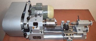
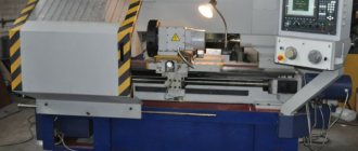
The first model of the Universal table lathe with two round guides was developed by ENIMS and produced by the Moscow machine-tool plant StankoKonstruktsiya.
The first Station wagons had a cast iron frame and two cylindrical guides made of durable hardened steel. The principle of creating this design is borrowed from the Unimat SL model from EMCO (Austria), which has been selling up to 15 thousand machines of this model per year for more than 40 years. In 1968, the Universal-2 screw-cutting lathe appeared, with a low-power engine.
In 1975, the Universal-3 was launched with one guide of a larger diameter instead of two, of a smaller diameter. Due to the complex process of adjusting the alignment of the spindle and tailstock when returning to the bed after dismantling, the headstock was made non-removable. Let's take a closer look at the TSh-3 model, which represents the entire line of Station Wagons.
Description of the operation of the electrical circuit of the Universal-V lathe
Electrical equipment is powered from a single-phase alternating current network with a voltage of 220 V and a frequency of 50 Hz.
Starting and stopping the electric motor is carried out using the KV relay (see Fig. 14), which is controlled by the SB2 (start) and SB1 (stop) buttons. When starting, the KV relay turns on and becomes self-powered, connecting the electric motor to the network with its contacts and providing zero protection, i.e. turning off the electric motor when there is no voltage in the network. The electric motor is protected from overload by the start-up relay A, which breaks the starting circuit, which turns off the KV relay. Restarting is possible only after 15-50 s, i.e. after the thermal protection elements of the start-up relay A return to their original position.
When starting the electric motor, its starting torque increases due to the connection of the starting capacitor C1 by the contacts of the start-protective relay A in parallel with the running capacitor C2. After the electric motor accelerates and the starting current decreases, capacitor C1 is turned off.
Reversing the electric motor is carried out using the switch SA, which, with the middle (vertical) position of the handle, ensures that the electric motor is turned off, i.e. it stops even when the KV relay is turned on. The handle should be left in a neutral position
Specifications
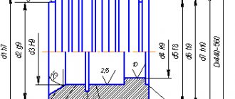
- Workpiece diameter. Above the bed - up to 150 mm, above the support - up to 90 mm.
- The length of the part in the centers is up to 250 mm.
- Cutter holder. Size – 8x8 mm.
- Drilling holes. Diameter - up to 8 mm.
- Inner spindle hole. Diameter 15 mm.
- The number of spindle rotation steps is 9.
- The spindle rotation range is from 200 to 3200 rpm.
- The length of the longitudinal movement of the caliper is 215 mm, the transverse movement is 90 mm.
- The longitudinal feed values are from 0.05 to 0.175 mm/rev.
- Machine weight 62 kg, dimensions: 690x410x230 mm.
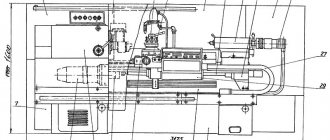
During operation, the machine provides accuracy class “N” (normal). Cast iron bed. After casting it is subjected to natural aging.
The flat bed guide and the round guide installed in the bed serve as a common base for the spindle headstock, tailstock and longitudinal slide. A lead screw, covered with a protective casing, is mounted in the front part of the frame.
The headstock (often a spindle headstock) contains a spindle, at the front end of which thrust bearings are installed, operating under the influence of radial and axial forces. A 4-speed pulley driving the headstock shaft is mounted at the other end. There is also a mechanism (snaffle) installed here that changes the direction of rotation (reverse) of the propeller.
Machine drive. On the left wall of the headstock there is a bracket with an electric motor and machine drive mechanisms and an asynchronous machine motor with a power of 370 W, connected to a 220 V network with a frequency of 50 Hz.
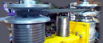
Under the bracket assembly cover are located:
- stepped pulleys of the V-belt mechanism (9 rotation speeds);
- intermediate shaft with eccentric for adjusting belt tension;
- gear unit for the lead screw drive.
The feed mechanism (guitar) is designed to control the rotation settings of the lead screw through the gears in the bracket assembly.
The apron (the switching unit for the lead screw nut) is attached to the caliper carriage.
The caliper is used to move the tool holder. Comprises:
- carriages;
- cross slide;
- upper slide;
- tool holder assembly.
The tailstock is designed for:
- aligning the workpiece axis with the axis passing through the centers of the spindle and the centering mechanism of the tailstock;
- ensuring the rigidity of mechanisms during processing;
- securing drilling cutting tools;
- installation of moving and fixed centers.
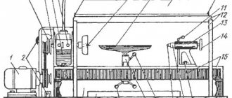
System and controls
Key control units are shown in the diagram.
- Handle for adjusting the feed movement. With its help you can activate the caliper and select the direction of its movement.
- Main movement adjustment knob. Activating the forward or reverse movement of the spindle stops its operation.
- Handle for moving the caliper (transverse).
- Handle for moving the tool holder.
- Handle for fixing the quill.
- Handle for moving the caliper (longitudinal).
Instructions for use, passport
Detailed instructions in printed form are available to any master. In addition, professionals have developed recommendations and detailed instructions for using machine tools.
If necessary, collet clamps of various sizes can be installed at the working end of the spindle instead of a lathe chuck.
The machine, with a factory set of equipment, allows you to:
- make gears;
- restore splines;
- drill a longitudinal groove in a bushing or in a block of rectangular cross-section;
- grind the part to the desired cone.
A simple changeover transforms the lathe into other types of devices to perform:
- milling and drilling works;
- jointing of planes of wooden blocks;
- grinding and polishing surfaces;
- sawing parts with a jigsaw;
- sawing with a circular saw;
- sharpening and straightening of cutters, other cutting and household tools;
- spring coiling;
- cutting threads (external and internal) with dies and taps.
The lathe's passport can be downloaded for free at the link - Universal lathe-3 (TSh-3) lathe's passport.
The machine must be installed:
- in an area of natural light and ventilation;
- Rigidly mount on a workbench or work table that absorbs vibrations.
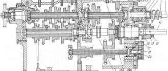
Principle of operation
How exactly TV 3 works is reasonable to consider based on the description of the kinematic diagram. The main functional movement is the rotation of the workpiece clamped in the headstock spindle chuck. Power transmission for this process is carried out from the main drive through a V-belt drive. In this case, it is possible to change the rotation speed by changing the gear ratio of the gearbox gears. The possibility of reverse rotation of the workpiece is also provided.
The second functional movement provided by the kinematics of the machine is working with a cutting tool. The approach to the processing zone can be carried out either manually, by rotating the corresponding wheel, or mechanically. For the latter, a feed box and a running roller are used. These two structural elements transform the cyclic rotation of the main drive shaft through a transmission device into a longitudinal/transverse, purely translational displacement of the caliper with a toolholder block.
The movement step of the caliper is regulated by the feed box by changing the gear ratio to select the required rotation speed of the lead screw. To change the depth of cut or the amount of material removed during turning, the mechanics of shifting the caliper tool holder in the transverse direction are used. This is achieved by using a sled design driven both mechanically and by a manual adjustment wheel designed for this purpose.
The TV3 machine allows you to cut threads manually by adjusting the position of the cutter with the corresponding feed wheels in the longitudinal and transverse directions. A mechanical method with transmission of torque from the main drive is also available. In this case, it is necessary to repeatedly pass the cutter over the workpiece. The mechanical cutting method shows much higher accuracy of work, with reduced requirements for personnel qualifications.
The TV 3 machine provides for installing a chuck on the tailstock quill cone. This allows you to cut internal and external threads using a wide range of taps and dies. Also, this functionality is convenient for drilling blind and through holes in workpieces and performing boring operations.
Precautions when working with equipment
- Conscious adherence to safety measures during operation, as well as during transportation and installation indoors.
- In the electrical circuit, ensure the serviceability of the emergency de-energization device.
- The workroom should be equipped for fire protection.
- Place emergency medical supplies and medications within easy reach.
- Work clothes should be adjusted so as to prevent accidental contact with rotating mechanisms.
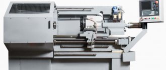
The prototype of the new screw-cutting lathe MetalMaster -1830 remains the TSh-3 model of the machine even before the perestroika, Soviet brand Universal - 3. It looks aesthetically pleasing, is equipped with a smooth drive control, and is equipped with electronics. And, most importantly, the machine has made a qualitative transition from an amateur machine to the category of a professionally advanced machine for metalworking.
Regulations for specialist actions
Work with the machine must be carried out taking into account certain recommendations:
- There is play between the workpiece and the grinding wheel. It is necessary to ensure that its thickness is half that of the workpiece.
- Work with workpieces should only be done after the main shaft has completely untwisted. Otherwise, damage to the machine or injury to the operator may occur.
- The unit is installed on a special workbench or on the floor. In this case, the weight of the unit is taken into account.
- After installing the equipment, it is necessary to check its stability. If the machine wobbles, this will lead to poor-quality processing of workpieces.
- If the equipment is damaged or inoperative, its operation is strictly prohibited for safety reasons.
- The parts to be turned must be installed above the horizontal line, the passage of which is observed in the center of the grinding wheel. For this purpose, handholds are installed.
- The presence of flammable and explosive substances in the room where they are working on the part is strictly prohibited.
- The equipment operates from a three-phase network, the voltage of which is 380 volts.
- The frame and other components of the device must be regularly maintained. They must be cleaned of waste that appears during the processing of metal products.
- It is allowed to work with the unit only in special clothing; in addition, the operator is recommended to wear safety glasses.
Structural components of the machine and their characteristics
The classic assembly scheme is used. The functional cutter is controlled mechanically or manually. Starting and stopping are carried out using a special button.
Machine bed
The bed is a necessary connecting element of a lathe. Thanks to it, all nodes are securely attached to each other and can work together. In this case, the front part of the frame is the mechanism for moving the carriage, and the rear part is necessary for the operation of the tailstock. A rack and a lead screw are installed on the front side. The shape of the frame itself is box-shaped, there are two guides. The bed is kept in a constant position on two pedestals, which ensure the safety of using the TV 3 machine.
Headstock
The headstock has two main properties. The first is that it supports and prevents the part that is currently being processed from falling out of the unit. The second purpose is to impart rotational movement to the element, making processing possible. In TV 3, the headstock serves as a gearbox. The transmission of motion occurs according to the following algorithm:
- individual electronic carrier;
- spindle;
- first shaft;
- gear mounted on the first shaft;
- second shaft;
- several types of gears on the second shaft;
- third shaft;
- several gears on the third shaft.
The last block of gears engages with the blocks of the second ones and gives them movement. As a result, the blocks are transferred to the spindle of the main machine, which processes the element. In this case, this happens with the help of a washer that is installed on the thread of the device.
The rotational torque is transmitted several times and reaches the required size and power
The positioning and alignment of the gears on the multiple shafts is important, as they determine how much power is delivered. The gear ratio is determined by what the number of revolutions will be
Transmission mechanism
The mechanism is necessary for the transmission of torque from the gearbox to the gears. The caliper speed and pitch changes depending on the position of the gears. The transmission mechanism includes a bracket with the first roller of three gears (72 teeth), the second of four (42 teeth). The second shaft is engaged with the next gear (70 teeth), and the first with the gearbox. There is a formula that determines the size of the gear ratio: i = 24/72 * 42/70 = 1/5.
The number of gear ratios remains constant, since in the TV 3 lathe it is not possible to install gears with different technical characteristics and the number of gear teeth. The operation of the mechanism is dangerous; the student is protected by a layer of iron, which is installed in the form of a casing.
Gearbox
The box receives its torque from the transmission mechanism. At the same time, it is possible to set the caliper feed from 0.4 to 0.6, and the thread in increments from 0.6 to 1 mm.
Depending on the movement of the gear, the stroke of the roller changes. If the lever is placed to the left, then the clutch clings - the movement will be at the lead screw.
The gearbox is protected from external influences. Oil can be poured into the mechanism, when necessary, through special holes. The box is tightly attached to the frame.
Caliper
The support allows you to attach and move the cutter depending on the size, diameter and shape of the workpiece. The support on the TV 3 lathe has four carriages that drive the corresponding nuts and screws into operation. The caliper is a part that often wears out due to the appearance of a gap between the carriages. If problems arise, regulation is carried out using special bars.
Apron
The apron is designed to regulate the flow. By means of it, it is regulated, the work takes place using a lead screw, a roller, manually or mechanized. Manual and mechanical feeding are carried out using different methods. The first is using a flywheel on the second shaft, and the second is thanks to a sliding key.
Types of machine functions and its design
Universal 2 is a machine that can be quite easily transformed into a drilling or milling machine. Therefore, it can be used to cut, trim, cut threads with a cutter, bore holes, and sharpen simple or shaped surfaces. And after moving the main movement unit to a vertically mounted guide, drill, countersink and even mill, as well as grind the planes. Using optional accessories allows you to do the following:
- Sharpen cutting tools.
- Cut sheet material straight (with a circular saw).
- Plane a tree.
- Cut parts of any shape from sheet material (with a jigsaw).
The headstock of the product and two guides are attached to it. The main motor is located on the headstock of the product. The thrust head is installed on the guides. The rotation of the spindle by the main and only motor occurs through pulleys and a V-belt. And the feed mechanism, often called a guitar, is connected to the source of movement by a gear transmission.
Design features of the TSH-3 model
The design features of the TSh-3 machine usually include the following parameters:
Design features
- The presence of a rigid frame, reinforced with metal corners, with the ability to adjust the lift level.
- The equipment is supplied in a floor-standing version.
- For safe operation, there is a device for emergency engine stop and forced braking of the rotating shaft.
The caliper movement stop device is triggered when the engine is overloaded. There are also transparent shields to protect against flying sparks or abrasive particles bouncing off the rotating wheel.
For installation, you will need to prepare a place that can withstand the weight of the machine and possible vibrations during its operation. There is no need to prepare a place for installation on a workbench.
In addition to the basic one, there are two additional modifications of the sharpening and grinding machine:
- TSh-3-10 with illumination using an electric lamp with a lampshade installed in the upper part.
- TSh-3-01 with increased engine power.
TSh-3-01, unlike TSh-3-03, has increased engine power