Specifications
The characteristics of the machine indicate its good versatility.
Using the 2N135 machine, you can perform technological operations with workpieces made of a variety of materials, and with a fairly wide range of sizes. Thanks to the use of tools made from high-speed steels and alloys with high hardness, this equipment is capable of performing various jobs. The main technical characteristics on which the functionality of any equipment depends are: spindle stroke; largest drilling diameter; maximum gap between the work table and the spindle; number of revolutions per minute; working surface size.
For the 2N135 machine these parameters look like this:
- The distance between the guides and the spindle axis is 300 mm.
- The maximum diameter of holes that the machine can make in steel is 35 mm.
- The minimum distance between the base plate and the end of the spindle is 700 mm, the maximum is 1120 mm.
- The minimum distance between the work table and the end of the spindle is 30 mm, the maximum is 750 mm.
- The maximum torque the spindle can develop is 400 Nm.
- Rotation speed from 31.5 to 1400 rpm.
- The number of rotation speeds is 12.
- The maximum spindle stroke is 250 mm.
- With one revolution of the flywheel-handle, the spindle moves 122.46 mm.
- The division of the dial corresponds to a spindle stroke of 1 mm.
- The maximum feed force is 15 kN.
- During one revolution, the spindle feeds 0.1-1.6 mm.
- Feed adjustment - 9 steps. All modes are set manually. There is a dynamic spindle stop system.
- The dimensions of the work table are 450×500 mm; in the vertical plane, the work surface can move by 300 mm. There are three T-slots.
- Dimensions of the machine 2Н135—2535×825×1030 mm.
- The power of the electric motor that powers the spindle feed is 4 kW.
- The supply of cooling liquid to the processing zone is carried out by an electric pump of the X14−22M series.
- The weight of the machine is 1200 kg.
This machine, like all other equipment assembled in the production shops of the machine-tool plant in the city of Sterlitamak, is made wisely and conscientiously. Plastic parts, which are widely used by modern manufacturers to reduce the cost of their products, are completely absent from the design of this machine. This factor provides a complete guarantee that the equipment can be repaired in case of any breakdown. Moreover, repairs will not be very expensive due to the wide range of spare parts on the market.
Of course, this machine is inferior to modern equipment in many technical characteristics. Drilling machines from good manufacturers are superior to 2N135 in speed of operations, drilling accuracy, ergonomics and ease of use. However, if reliability, functionality and minimal cost are important to you for performing drilling work in a garage or small workshop, then you cannot find a better machine than the 2N135 machine.
The main advantages of this equipment are durability, endurance and easy repair.
Description of the design of the main components of the drilling machine 2A135
Gearbox and feed box
Gearbox and feedbox of drilling machine 2A135
Spindle of drilling machine 2A135
Spindle of drilling machine 2A135
Spindle 2 (Fig. 6) is adjusted in the axial direction by tightening nut 1 through the window located on the front part of the bracket.
Axial feed forces are perceived by thrust bearing 3.
The spindle is balanced by a weight placed in the machine column.
The spindle bearings are lubricated with a wick from the cavity of the feed box. The oil supply should be one drop per minute.
Spindle bearings for drilling machine 2A135
The spindle of the 2A135 machine is mounted on 3 bearings:
- 2. Lower bearing No. 710 single-row radial ball bearing, accuracy class H(0), size 50x80x11 mm
- 3. Bearing No. 8210 thrust ball, accuracy class N(0), 40x78x22
- 2. Upper bearing No. 710 single-row radial ball bearing, accuracy class H(0), size 50x80x11 mm
Technical characteristics of bearing No. 710
Bearing 710 is an open type single row deep groove ball bearing.
Designed to withstand radial loads at high rotation speeds. The 710 bearing is currently not available.
Dimensions and characteristics of bearing 710 (6206)
- Inner diameter (d): – 50 mm;
- Outer diameter (D): – 80 mm;
- Width (H): – 11 mm;
- Weight: – 0.213 kg;
- Number of balls in the bearing: - 18 mm;
- Ball diameter: - 6.35 pcs;
- Dynamic load capacity: - 16 kN;
- Static load capacity: - 11 kN;
- Maximum rated speed: - 9000 rpm.
Bearing diagram 710
Feed box model 2A135
To change the feed rate on the model 2A135 machine, a box is used, consisting of two standard mechanisms with sliding keys. A longitudinal section of the feed box is shown in Fig. 56.6.
From the kinematic diagram (Fig. 55, a) it is clear that the feed movement is borrowed from the spindle. Next, through the gear block 1 (Fig. 56.6), installed on axis 2, and the gear wheel 3, rotation is transmitted to the hollow shaft 4 with a slot in. On the latter, three gears 16 are freely installed, having keyways b. Between gears 16 there are intermediate rings. A rod 14 moves inside the hollow shaft 4, representing a round rail in its lower part. In the upper part of the rod 14 there is a through window in which a sliding key 15 is installed on the axis. This key, under the action of the spring 17, tends to go into the keyway of one of the gears 16.
By moving the rod 14 with the sliding key 15 inside the shaft 4, you can connect the latter with any of the gears 16. Intermediate rings, which do not have keyways, recess the sliding key at the moment of switching speed. This is necessary to prevent damage that could occur if two gears jam on the shaft at the same time.
A similar mechanism, consisting of four gears 10 with grooves a, a sliding key 8, a leaf spring 9 and a rod 7, is installed on a hollow shaft 11.
A cone of gears 13, consisting of five wheels, is fixed to the shaft 12. The three upper wheels of the cone are in constant engagement with gears 16, and, in addition, the upper and three lower ones are in constant engagement with gears 10 of shaft 11. The movement of rods 7 and 14 with sliding keys 8 and 15 to switch the spindle feed rate is carried out by handles, located on the left side of the spindle head housing.
The plunger pump 6 is driven by an eccentric 5.
Feed mechanism . Switching on and off the mechanical feed, as well as the approach and removal of the spindle, is carried out by the steering feed mechanism shown in Fig. 56, a. The spindle feed mechanism of the model 2A135 vertical drilling machine consists of a worm gear, rack and pinion gear, control handles and a number of clutches. The feed mechanism is driven from the feed box through a cam clutch 16, designed to automatically turn off the feed movement upon reaching a given drilling depth and at the same time being a safety device that turns off the feed movement chain in case of overloads. The maximum load on the feed mechanism is regulated by screw 15, which pre-compresses spring 14.
To turn on the mechanical feed, the steering wheel 3 and the cam clutch 22 connected to it are turned towards themselves. The angle of rotation of the steering wheel and coupling is equal to 20° and is limited by the slot a on the coupling and the pin 21 attached to the end of shaft I. When turning the steering wheel 3, the teeth of the coupling 22, which have bevels, shift the cam cage 4 to the right and, entering the end face of the cage teeth, fix this is a displacement. Attached to the cage 4 is a double-sided ratchet disk 6, connected to the cage 4 by spring-loaded pawls 5. When the cage is displaced, the teeth of the ratchet disk 6 engage with the teeth of the disk 9 attached to the worm wheel 7 and connect the latter to shaft I. Thus, rotation from the feed box through coupling 16 communicates with worm 13, worm wheel 7 and shaft 1, the rear end of which is a rack and pinion gear. The latter is engaged with a rack cut on sleeve 10 of spindle 11 of the machine.
Quick approach of the tool to the workpiece is ensured by further turning the steering wheel 3 with the feed switched on. In this case, the dogs 5 slip over the teeth of the inner side of the disk 6, ahead of the mechanical feed.
Switching off the mechanical feed at any time is carried out by turning the steering wheel 3 away from you by 20°, while the teeth of the clutch 22 will become opposite the depressions of the holder 4, the latter will move to the left under the action of the spring 8, the teeth of the ratchet disk 6 will disengage from the teeth of the disk 9, as a result of which the worm wheel 7 will rotate freely on shaft I and the mechanical feed of the spindle will stop.
When the spindle is raised quickly, the mechanical feed is also automatically switched off.
The design of the feed mechanism of the vertical drilling machine model 2A135 also allows for slow manual movement of the steering wheel 3, sleeve 10 with the spindle. To do this, it is necessary to turn off the mechanical feed with the steering wheel 3, and then move the ring 2 along the axis of shaft I to the right; in this case, the pin 20 will block the pin 21 and when the steering wheel 3 is turned toward itself, the mechanical feed will not be turned on.
Adjustment of the feed mechanism for drilling holes of a given depth is carried out by cam 18, which is set to the required size on the scale of dial 19.
When setting up the machine for tapping threads, reversing the spindle to remove the cutting tool can be done automatically or manually. With automatic reverse, adjustment to the cutting depth and switching of the spindle is carried out by cam 17, which is pre-installed on dial 19. With manual reverse control, when the required cutting depth is reached, the direction of rotation of the spindle is changed by handle 12.
Radial drilling machines mod. 2A554, 2A576 and 2A587
Technical specifications:(2a532)
| Parameter | 2A554 | 2A576 | 2A587 |
| Maximum drilling diameter for steel | 50 | 80 | 100 |
| Maximum drilling diameter in cast iron | 63 | 100 | 125 |
| Maximum cutable threads for steel | M52x5 | M80x40 | M100x4 |
| Spindle torque | 750 | 1600 | 2800 |
| Spindle axial force, N | 20000 | 32000 | 50000 |
| Main drive power | 5,5 | 7,5 (11) | 11 |
| Spindle axial stroke | 400 | 500 | 630 |
| Stroke of the drill head along the sleeve | 1225 | 2000 | 2635 |
| Sleeve stroke along the column | 710 | 1100 | 1500 |
| Angle of rotation of the sleeve around the column (deg.) | 360 | 360 | 360 |
| Spindle feed range: | (mm/rev.) 0.045 - 5.0 | (mm/min.) 2 - 1600 | (mm/min.) 2 - 1600 |
| Number of spindle speeds | stepless | stepless | |
| Spindle taper | MK5 | ISO 50 | ISO 50 |
| Overall dimensions of the machine (length/width/height), mm: | 2665/1030/3430 | 4180/1280/4125 | 4850/1830/4912 |
| Weight | 4700 | 11850 | 17150 |
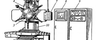
Features of the engine design
The gearbox is a cast iron body consisting of two main elements:
- spindle gearbox,
- speed change mechanism.
A vertically located electric motor, through a V-belt type transmission, transmits movement to the speed mechanism.
The electric motor of the drilling machine itself is fixed on the bracket. The bracket is able to make movements along the body axis. Thanks to the movement of the bracket, the required belt tension is ensured.
There is a hole in the front of the spindle head. Through it the spindle of the apparatus is regulated. A load is suspended in the machine column. Its task is to balance the spindle. Spindle bearings require constant lubrication. The bearings are lubricated with one drop of lubricant every minute.
Table of contents
The 2A125 vertical drilling machine is designed to perform various operations (drilling, reaming, reaming, countersinking, and threading) in small-scale production.
The maximum drilling diameter is 25 mm, provided by a nine-speed gearbox with a range of 97-1360 rpm. and a nine-speed feed box with a range of 0.1-0.81 mm per spindle revolution.
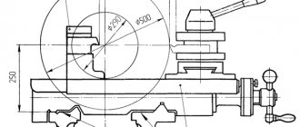
Installation, workspace dimensions
Kinematic diagram of a vertical drilling machine 2A125
The device of a vertical drilling machine
The 2A125 vertical drilling machine consists of the following components:
- Column with table and stove;
- Gearbox;
- Gearbox;
- Feed mechanism;
- Spindle;
- Electrical equipment;
- Cooling system
Vertical drilling machine gearbox
The gearbox of a vertical drilling machine receives torque from a standard drive – an electric motor and a belt drive. The engine is mounted on a bracket, which also serves as a belt tensioner. The bracket is fixed using two bolts 5.
The cast iron gearbox housing houses a gear reducer and a gear shift mechanism.
The gear ratio and nine spindle speeds are changed using two triple movable gear blocks 3 and 4.
The moving blocks are moved by forks, controlled by two handles, located in the gearbox housing.
The gearbox is mounted on a stand, inside of which there is a tank with oil magma-diesel.ru/. The gearbox is lubricated using oil pump 1, located under the casing.
Feed mechanism of vertical drilling machine
The feed mechanism of a vertical drilling machine includes the feed mechanism itself, the spindle and the feed box.
The feed mechanism is driven into rotation from the feed box through the cam clutch 20. The cam clutch is designed to turn off the mechanical feed from the cam 16 located on the limb 22, and also serves as a safety device in case of overload. The clutch is adjusted to disengage using screw 18 and spring 19.
Manual spindle feed is carried out through rack and pinion gear 10 and the spindle sleeve. To do this, it is necessary to turn off the mechanical feed with the steering wheel 14, and then move the ring 1 in the axial direction of the shaft 2, while the pin 11 blocks the pin 13.
Threading in a manual tap is carried out using an electric reverse, controlled both manually and automatically. When the required depth of the thread being cut is reached, by manual control, handle 15 switches the direction of rotation of the spindle, withdrawing the tap.
Automatic reversal is adjusted using cam 16 located on dial 22.
Feed box of vertical drilling machine
The feed box of a vertical drilling machine is mounted in the feed mechanism housing and is driven by gear 1, which sits on the splined joint of the spindle and meshes with double gear 2. In turn, the double gear transmits torque through gear 3 to cone 4.
The gearbox has 9 feeds in the range from 0.1-0.81 mm/rev.
Vertical drilling machine spindle
The spindle supports of the vertical drilling machine are ball bearings 1. Axial feed loads are perceived by thrust bearing 4 installed in cup 3.
The bearing is adjusted by tightening the nut through the window in the front part of the bracket.
The spindle is balanced by a weight placed in the column of the machine.
Purpose of the device and scope of its use
The 2A135 vertical drilling unit is designed to perform a wide range of operations:
- countersinking,
- opening holes,
- countersinking,
- cutting blank ends,
- cutting with threaded taps.
Performing a wide range of work allows the unit to be classified as a universal device. This device is not intended for mass production and is not used in industrial enterprises that produce a wide range of products. The use of the machine is limited to small-scale production of single products.
The equipment is ideal for repair departments of factories and tool shops. Subject to improvements in the design, the unit can be used for mass production of products.
The machine belongs to the fourth placement group. The device is equipped with cutting tools made of three main types of material:
- high alloy steels,
- high speed steels,
- high hardness alloys.
The unit has a relatively small work table. For this reason, small-sized parts are processed on it. Suitable products for machining are:
- cast iron parts,
- blanks from different types of steel,
- parts made of non-ferrous metals.
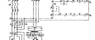
Electrical equipment and electrical circuit of the drilling machine 2A135
Electrical diagram of drilling machine 2A135
List of elements of the electric vertical drilling machine 2A135
- electric motor A42-2
- thermal relay RT-1
- fuses PR-60, NE-27
- input switch VP-25
- lighting switch VT-1
- lighting lamp
- step-down transformer TPB-50
- microswitches MP-1
- microswitches MP-1
- microswitches MP-1
- electric pump switch VPZ-10
- electric pump PD-22
KP and CL - magnetic starters MPKO-111
Electrical equipment of a vertical drilling machine 2A135. General information
The electrical equipment of the machine consists of the following components:
- Three-phase asynchronous squirrel-cage electric motor type A42-2 with a power of 4.5 kW, used for spindle rotation and tool feed
- Electric pump PD-22 with a power of 0.125 kW
- Starting and protective equipment built into the niche of the machine column
- Command equipment consisting of three microswitches controlled by a handle
- Switching wires running mainly along the internal cavities of the column
The machine can perform both drilling with automatic shutdown of the feed at the end of drilling, and thread cutting with automatic or manual reversal of tool rotation. The adjustment is made by rearranging the cam on the dial.
Description of the electrical circuit of the vertical drilling machine 2A135
- By turning on the input batch switch (IPB) 4, voltage is supplied to the starting and control equipment; pump package switch (VPN) 11 is used to turn the cooling pump on and off
- In the initial (middle) position of the handle, contacts a and b of microswitch 10 are open, the control circuit is de-energized
- To start the machine, the control handle is moved down, contacts o and b and contacts b and d of microswitch 9 are closed, the gearbox starter is turned on, turning on electric motor 1. If the machine was set up for drilling, then at the end of processing, depending on the setting, the feed is turned off without turning off rotation. The spindle is retracted manually.
- If the machine was configured for thread cutting, then upon completion of cutting, the cam mounted on the limb, through a special mechanism, acts on microswitch 8, contacts b and c of which open, and the gearbox starter is turned off; contacts b and d close, as a result of which the CL reversing starter is turned on.
- The engine is reversed, the tap is unscrewed from the product. When the tap is withdrawn, contacts b and d open, but the CL starter is powered through block contacts d and e
- For the next operation, it is necessary to press the handle to the “right” position, as a result of which the CL starter is turned off and the GB starter is turned on
- At any time, the machine can be turned off by moving the handle to the middle position and the engine can be reversed manually by moving the handle up
Protection of electrical equipment of a vertical drilling machine 2A135
The circuit provides protection against short circuit, overload and zero protection.
The bracket is grounded by an additional conductor.
The machine must be grounded, for which there is a special bolt.
Maintenance of electrical equipment is carried out according to standard instructions.
Device characteristics
The unit is equipped with a spindle whose stroke is 225 mm. Its rotation frequency is at least 68 revolutions per minute. The spindle can make a maximum of 1100 revolutions per minute.
The machine is characterized by the following technical characteristics:
- for steel grade 45, the maximum drilling diameter is 35 mm;
- the gap from the spindle end to the plate is 705 mm minimum, maximum value is 1130 mm;
- the distance from the spindle end to the work table is maximum 750 mm;
- dimensions of the device in length, width, height, respectively - 1240 * 810 * 2500 mm;
- machine weight - 1299 kg;
- desktop dimensions - 450*500 mm;
- number of T-shaped slots - 3;
- the maximum vertical movement of the table is 325 mm;
- maximum spindle stroke - 225 mm;
- number of speeds provided for the spindle - 9;
- number of feed stages - 11;
- maximum feed force - 1599 kg.
Technical features
A special feature of the machine is that it has a dynamic spindle braking system.
The electrical equipment of the unit is presented in the form of an electric motor with a power of 4.4 kW. The device is equipped with an electric pump that supplies coolant. The pump is type X14-22M.
The specified vertical drilling machine has a number of technical features:
- the maximum possible diameter of parts that can be drilled on the machine is 50 mm;
- the spindle, due to the presence of a reversing device in the apparatus, is capable of rotating in different directions;
- The device is equipped with a 9-speed gearbox, thanks to which the spindle makes up to 1100 revolutions per minute;
- the unit is controlled exclusively manually; no automated systems are provided for it.
The 2a135 drilling machine allows the use of machine taps designed for thread cutting, which is ensured by the presence of a reversible device in the design.
To obtain the proper work result, it is recommended to use materials made of hard alloys as cutting tools for the machine. It is recommended to perform drilling of products at low tool speeds due to the low power of all equipment.
Unit design
The design of the drilling machine includes:
- bed,
- table,
- feed unit,
- plate,
- electric motor,
- spindle,
- speed block,
- a handle that moves the surface vertically,
- handle for manual spindle feed.
For protective purposes, a clutch is provided in the feed block. It protects the unit from failure when the system is overloaded. The actuated clutch helps cut off the mechanical feed.
The purpose of the plate is wide. It stores the coolant supplied to the working element of the device. The liquid is stored in a special tank built into the stove. The base plate itself is made of cast iron. An electric pump is installed on the plate, communicating with the coolant reservoir through tubes.
The amount of liquid supplied to the working element of the machine is regulated using special taps installed on the tubes.
The cooling system of the unit constantly needs to clean the sump. Various waste contaminants periodically accumulate in it, interfering with the normal operation of the equipment. It is necessary to clean the sedimentation tank once a month or more often.
Performing various types of work on the unit
The device allows you to perform drilling operations. The technology for performing this operation on a machine requires the use of a drill with a larger diameter than the diameter of the jumper on another drill. With this approach, the axial drag force becomes significantly smaller.
When drilling a product, the jumper should cut into it and not squeeze out the metal. In the second case, there is a serious increase in axial resistance.
The vertical drilling machine has a countersinking function. Only specific types of products are subject to such an operation:
- stamped;
- forged;
- having holes inside in the shape of a cone or cylinder;
- cast.
Deployment on the unit is carried out in two stages:
- at the first stage, a cylindrical hole is drilled in the workpiece, after which it is subject to processing with a stepped conical countersink;
- at the second stage, the metal product is first rough processed with special reamers, after which finishing reaming is performed by installing a conical reamer with smooth edges.
Unit design
The design of the drilling machine includes:
- bed,
- table,
- feed unit,
- plate,
- electric motor,
- spindle,
- speed block,
- a handle that moves the surface vertically,
- handle for manual spindle feed.
For protective purposes, a clutch is provided in the feed block. It protects the unit from failure when the system is overloaded. The actuated clutch helps cut off the mechanical feed.
The purpose of the plate is wide. It stores the coolant supplied to the working element of the device. The liquid is stored in a special tank built into the stove. The base plate itself is made of cast iron. An electric pump is installed on the plate, communicating with the coolant reservoir through tubes.
The amount of liquid supplied to the working element of the machine is regulated using special taps installed on the tubes.
The cooling system of the unit constantly needs to clean the sump. Various waste contaminants periodically accumulate in it, interfering with the normal operation of the equipment. It is necessary to clean the sedimentation tank once a month or more often.
Engine and gearbox design
The drilling unit has design features.
The machine spindle is fixed in supports using precision bearings, which ensures smooth and accurate drilling of products.
The same device is responsible for turning on and off feeds and quickly moving the spindle, which significantly saves time on additional operations.
The cutting tool is fed automatically immediately after it is brought to the surface of the product. The machine table moves horizontally during operation.
The vertical drilling machine is equipped with a special stopping mechanism with a stop, with the help of which the feed of the cutting tool is switched off automatically when the desired drilling depth is reached.
The unit provides the possibility of replacing the drive pulleys that are part of the V-belt drive.
Adjustment and setup of drilling machine 2A135
After installing the machine at the workplace, cleaning, filling with oil and lubricant, connecting to the electrical network, checking operation at all speeds and feeds, no adjustment is required. Setting up the machine consists of installing the table and bracket in the positions required for operation and clamping the bracket wedge, as well as setting the speed and feed rates.
The clearances in the spindle bearings are selected through a window on the front wall of the bracket, closed with a lid. When adjusting, you need to turn the spindle so that the adjusting nut screw is in the window, then, loosening the screw, tighten the nut and tighten the screw again.
The drilling depth is set using a dial as follows: by rotating the cross steering wheel towards you, lower the spindle until it comes into contact with the workpiece. We unscrew the screw of cam 17 (see the figure for turning off the feed and cam 18, turn until the edge of cam 17 coincides with the dial division corresponding to the drilling depth, and tighten the screws again. In this case, the division on the dial corresponds to the full drilling depth, including the conical part of the drill sharpening.
Cam 18 is used to configure automatic reversal of the spindle direction when cutting threads. The installation of this cam is similar to the installation of the mechanical feed switching cam. In this case, the feed cut-off cam is moved back 10 mm. The spindle rotation direction is changed by reversing the electric motor.
The knurled cap, located in the center of the cross handwheel, is used to turn off the power feed if you need to drill or tap with manual feed. To turn on manual feeding, the cap must be pressed away from you until it stops.
The belts are tensioned by moving the bracket with the electric motor using tension screws located on the rear wall of the gearbox. To tighten the spring of the safety clutch, which turns off the feed when overloaded, use a special screw with an internal hexagonal hole, located under the cap of the upper cover of the bracket. Normally, the spring is adjusted to turn off the feed when an axial force exceeds the rated feed force by 10%, i.e. at 1800 kg.
2A135 Universal vertical drilling machine. Purpose and scope
The 2A135 vertical drilling machine replaced an outdated machine in mass production 2135
. The new model provides more convenient control of the feed and feed box. Improved ergonomics. The 2A135 machine was replaced by a more advanced model 2N135
The universal vertical drilling machine, model 2A135, is designed for work in repair and tool shops, as well as in production shops with small-scale production; a machine equipped with accessories can be used in mass production.
Vertical drilling machine 2a135, with a nominal drilling diameter of 35 mm, is used in enterprises with single and small-scale production and is designed to perform the following operations: drilling, reaming, countersinking, countersinking, reaming, threading and trimming ends with knives.
Allows processing of parts in a wide range of sizes from various materials using tools from high-carbon and high-speed steels and hard alloys.
Drilling operations on machine 2a135
Design features of the drilling machine 2A135
The presence on the machine of a nine-speed gearbox with a control range of 68-100-140-195-175-400-530-750-1100 rpm, an 11-speed feed box with a control range of 0.115 to 1.6 mm per revolution and electric reverse provides selection of standard cutting modes for hole diameters up to 35 mm when drilling, reaming, countersinking, countersinking, reaming, threading, and also allows the use of cutting tools equipped with carbide.
The presence of mechanical spindle feed on machines, with manual control of work cycles.
Allows processing of parts in a wide range of sizes from various materials using tools from high-carbon and high-speed steels and hard alloys.
The machines are equipped with a device for reversing the main motion electric motor, which allows them to cut threads using machine taps while manually feeding the spindle.
The machine has high rigidity, strength of working mechanisms, drive power and a wide range of cutting speeds and feeds, allowing the use of cutting tools equipped with carbide. The presence of an electric reverse, controlled both automatically and manually, provides the ability to cut threads with manual approach and withdrawal of the tap.
The design of the vertical drilling machine model 2A135 provides for automatic switching on of the feed movement after the cutting tool is quickly brought to the workpiece and automatic switching off of the feed when the specified drilling depth is reached.
The specified drilling depth for blind holes is ensured by a special stopping mechanism with a stop. This mechanism is also a safety device that protects the feed mechanism from damage due to overload.
The machine spindle is mounted on precision rolling bearings. The lower support consists of a radial ball bearing of class AB. The upper support has one class B ball bearing.
The plant provides the possibility of changing the drive pulleys of the belt drive, which allows you to set the limits of the spindle speed in accordance with the technological tasks.
To reduce auxiliary time on the machine model 2A135, it is possible to turn the feed on and off using the same steering wheel that manually moves the spindle quickly.
Placement category 4 according to GOST 15150-69.
Analogues of vertical drilling machines 2A135, currently produced:
- 2T125, 2T140, 2T150 - manufacturer: Gomel Machine Unit Plant
- 2AS132, 2AS132-01 - manufacturer: Astrakhan Machine Tool Plant
- 2L125, 2L132, 2L135, LS25, LS35 - manufacturer: Lipetsk Machine Tool Enterprise (PJSC STP-LSP)
- MN25L, MN25N-01 - manufacturer: Molodechno Machine Tool Plant
Information about the manufacturer of the vertical drilling machine 2A135
Manufacturer of vertical drilling machines models 2A125, 2A135, 2A150, 2G175 - Sterlitamak Machine Tool Plant , founded in 1941 and the city of Frunze.
The history of the Sterlitamak Machine Tool Plant begins on July 3, 1941, when the evacuation of the Odessa Machine Tool Plant to the city of Sterlitamak began.
Already on October 11, 1941, the Sterlitamak Machine Tool Plant began producing special modular machines for the defense industry.
Currently, the plant produces metalworking equipment, including CNC lathes and milling machines, multifunctional machining centers.
Products of the Sterlitamak Machine Tool Plant
- 2135
— universal vertical drilling machine Ø 35 - 2A125
- universal vertical drilling machine Ø 25 - 2A135
- universal vertical drilling machine Ø 35 - 2A150
- universal vertical drilling machine Ø 50 - 2G175
- universal vertical drilling machine Ø 75 - 2N125
- universal vertical drilling machine Ø 25 - 2N135
- universal vertical drilling machine Ø 35 - 2N150
- universal vertical drilling machine Ø 50 - 2R135F2
- CNC vertical drilling machine Ø 35 - 2S125, 2S125-1 (2S125-01), 2S125-04
- universal vertical drilling machine Ø 25 - 2S132, 2S132K
- universal vertical drilling machine Ø 32 - 2С150ПМФ4
- vertical drilling-milling-boring machine with CNC and ASI 500 x 1000 - 2С550А
– radial drilling machine Ø 36 - 400V
- vertical drilling-milling-boring machine with CNC and ASI 400 x 900 - 500V (STC F55)
- vertical milling center 630 x 1200 - SF-16, SF-16-02, SF-16-05
- tabletop milling and drilling machine Ø 16
Where is the 2r135f2 CNC drilling machine used?
The machine in question is used to regulate the process of rectangular machining and positioning. The program carrier is a punched paper tape with eight tracks. The machine is equipped with a digital display; up to 15 adjustments per tool length can be entered.
The machine has a closed system in which the BS155A selsyn acts as sensors. The table and slide are positioned with an accuracy of up to 0.02 mm, digital display and movement assignments have a resolution of up to 0.01 mm. There are a total of 3 controllable coordinates, 2 of which can be used simultaneously.
Features of the engine design
The gearbox is a cast iron body consisting of two main elements:
- spindle gearbox;
- speed change mechanism.
A vertically located electric motor, through a V-belt type transmission, transmits movement to the speed mechanism.
The electric motor of the drilling machine itself is fixed on the bracket. The bracket is able to make movements along the body axis. Thanks to the movement of the bracket, the required belt tension is ensured.
There is a hole in the front of the spindle head. Through it the spindle of the apparatus is regulated. A load is suspended in the machine column. Its task is to balance the spindle. Spindle bearings require constant lubrication. The bearings are lubricated with one drop of lubricant every minute.
CNC drilling machine 2р135ф2: characteristics
- The maximum diameter of parts to be processed should not exceed 35 mm.
- The maximum size does not exceed 24 mm.
- The maximum milling width does not exceed 60 mm.
- The processing process involves 6 tools.
- Spindle speed 12.
- The working surface has the following dimensions - 710x400 mm.
- The spindle speed ranges from 35 to 1600 per minute.
- The number of feeds along the Z axis reaches 18.
- Working feeds along the Z axis range from 10 to 500 mm per minute.
- The table and slide move at speeds of up to 7000 mm per minute, and during the milling process 2200 mm per minute.
- The caliper movement frequency reaches 4000 mm per minute.
- In terms of dimensions, the machine has the following parameters: 1800 mm by 2400 mm by 2700 mm.
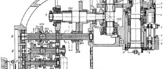
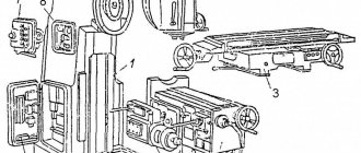
Kinematic diagram of the drilling machine 2A135
Kinematic diagram of the drilling machine 2A135
Movements in the machine
- Cutting movement - rotation of the spindle with the cutting tool
- Feed movement - axial movement of the spindle with the cutting tool
- Auxiliary movements are manual movements of the table and spindle head in the vertical direction and rapid manual movement of the spindle along its axis.
Cutting movement . Spindle V (Fig. 55, a) is driven by an electric motor with a power of 4.5 kat through a V-belt drive 140-178 and a gearbox.
On shaft I of the gearbox there is a triple movable block of gears B1, which provides shaft II with three rotation speeds. From shaft II, through gears 34-48, rotation is transmitted to shaft III, on which a triple movable gear block B2 is located, driving hollow shaft IV, connected by a spline to spindle V. As can be seen from the graph (Fig. 55, b), spindle V has nine rotation speeds. The highest number of spindle revolutions nmax, taking into account the elastic sliding of the belt, is determined from the expression = 1070 rpm.
Feeding movement . The feed movement is borrowed from spindle V. The movement is transmitted through gears 27-50 and 27-50, feed box with sliding keys, safety clutch M1, shaft IX, worm gear 1-47. gear coupling M2, shaft X and rack and pinion transmission to the spindle sleeve.
The feed box contains three- and four-stage mechanisms with sliding keys.
From shaft VI, three rotation speeds are transmitted to shaft VII, on which gears 60, 56, 51, 35 and 21 are rigidly fixed. From shaft VII, four rotation speeds are transmitted to shaft VIII.
Theoretically, the feedbox provides 12 rotation speeds, however, as can be seen from the graph (Fig. 54), one of them is repeated, so the 2A135 machine has only 11 different feed rates.
From shaft VIII, through the jaw clutch M1, movement is transmitted to shaft IX, on which the worm is fixed. The worm wheel is located on the same shaft with rack and pinion gear 14, which is in mesh with a rack cut on the spindle sleeve. The M1 clutch is used to protect the feed mechanism from damage during overloads, as well as to automatically turn off the feed when working on stops.
The highest feed rate smax is determined from the expression 3.14*3.5*14 = 1.6 mm/rev.
Auxiliary movements . The spindle head is moved from handle P1 through a worm gear 1-32 and rack and pinion gear 18, which engages with a rack m=2 mm fixed to the frame.
Vertical movement of the table is achieved by turning handle P2 through shaft XI, bevel gears 16-43 and lead screw XII.
Rapid movement of the spindle with the sleeve is carried out by a handwheel Ш connected by a special lock to shaft X. The lock allows the handwheel to rotate freely on shaft X within 20°, and subsequently connects them into one whole.
2A135 Universal vertical drilling machine. Purpose and scope
The 2A135 vertical drilling machine replaced an outdated machine in mass production 2135
. The new model provides more convenient control of the feed and feed box. Improved ergonomics. The 2A135 machine was replaced by a more advanced model 2N135
The universal vertical drilling machine, model 2A135, is designed for work in repair and tool shops, as well as in production shops with small-scale production; a machine equipped with accessories can be used in mass production.
Vertical drilling machine 2a135, with a nominal drilling diameter of 35 mm, is used in enterprises with single and small-scale production and is designed to perform the following operations: drilling, reaming, countersinking, countersinking, reaming, threading and trimming ends with knives.
Allows processing of parts in a wide range of sizes from various materials using tools from high-carbon and high-speed steels and hard alloys.
Drilling operations on the 2n135 machine
Design features of the drilling machine 2A135
The presence on the machine of a nine-speed gearbox with a control range of 68-100-140-195-175-400-530-750-1100 rpm, an 11-speed feed box with a control range of 0.115 to 1.6 mm per revolution and electric reverse provides selection of standard cutting modes for hole diameters up to 35 mm when drilling, reaming, countersinking, countersinking, reaming, threading, and also allows the use of cutting tools equipped with carbide.
The presence of mechanical spindle feed on machines, with manual control of work cycles.
Allows processing of parts in a wide range of sizes from various materials using tools from high-carbon and high-speed steels and hard alloys.
The machines are equipped with a device for reversing the main motion electric motor, which allows them to cut threads using machine taps while manually feeding the spindle.
The machine has high rigidity, strength of working mechanisms, drive power and a wide range of cutting speeds and feeds, allowing the use of cutting tools equipped with carbide. The presence of an electric reverse, controlled both automatically and manually, provides the ability to cut threads with manual approach and withdrawal of the tap.
The design of the vertical drilling machine model 2A135 provides for automatic switching on of the feed movement after the cutting tool is quickly brought to the workpiece and automatic switching off of the feed when the specified drilling depth is reached.
The specified drilling depth for blind holes is ensured by a special stopping mechanism with a stop. This mechanism is also a safety device that protects the feed mechanism from damage due to overload.
The machine spindle is mounted on precision rolling bearings. The lower support consists of a radial ball bearing of class AB. The upper support has one class B ball bearing.
The plant provides the possibility of changing the drive pulleys of the belt drive, which allows you to set the limits of the spindle speed in accordance with the technological tasks.
To reduce auxiliary time on the machine model 2A135, it is possible to turn the feed on and off using the same steering wheel that manually moves the spindle quickly.
Placement category 4 according to GOST 15150-69.
Operating principle of the drilling machine 2A135
The workpiece is installed on the machine table and secured in a machine vice or in special devices. The alignment of the axis of the future hole with the axis of the spindle is carried out by moving the device with the workpiece on the machine table.
The cutting tool, depending on the shape of its shank, is fixed in the machine spindle using a chuck or adapter bushings. In accordance with the height of the workpiece and the length of the cutting tool, the table and spindle head are installed.
Holes can be processed either by manual movement of the spindle or by mechanical feed.