Machine 3b151 technical characteristics
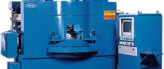
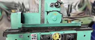
Care and Maintenance Guide. The cylindrical grinding machine model 3B151 is designed for external grinding of cylindrical products and flat cones.
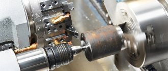
The following types of processing can be performed on the machine: — Longitudinal and milling grinding with manual control; — Longitudinal grinding with automatic transverse feed, carried out when the table is reversed; — Plunge grinding to the stop with a semi-automatic operation cycle; The machine of this model provides the ability to install active control devices, which are supplied with it by special order and for an additional fee. The machine is mainly designed to work in serial and mass production, but can also be used in individual production.
The modification of the machine does not have a hydraulic plunge mechanism. It is designed mainly for longitudinal grinding and is equipped with an automatic transverse feed mechanism, which occurs when the table is reversed. It can also perform plunge-cut and longitudinal grinding with manual transverse feed.
Model 3b151 machines are designed for external grinding of cylindrical and flat conical surfaces in mass production conditions.
Composition: General view
Software: KOMPAS-3D 15
Posted by vindjj
Date of: 2019-03-05
Views: 105
Add to favorites
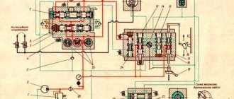
Hydraulic drive of machines models 3B151 AND 3B161
The hydraulic system of the machine is driven by a pumping unit consisting of a vane pump, a drive motor, a plate filter and an unloading valve (Fig. 22). The pumping unit is mounted on a separate plate fixed to the back of the machine bed stand.
The operation of the machine’s hydraulic system is controlled using the GSh-001A hydraulic panel mounted in the front part of the frame.
The hydraulic system of the machine performs the following functions:
- 1) moving the table;
- 2) table reverse;
- 3) moving the table when setting up the machine;
- 4) periodic feeding of the grinding head;
- 5) quick approach and removal of the grinding head;
- 6) tailstock quill retraction;
- 7) blocking the mechanism for manual movement of the table;
 sampling of play in the engagement of the nut and screw of the cross-feed mechanism.
Moving the table
The hydraulic movement of the table is started by installing the handle 50 in the position shown in the diagram (tilting the handle 11 to the right in Fig. 6).
In this case, oil is supplied from the pumping unit to spool 43 (Fig. 22) of the table reverse through the right section of valve 49. Depending on the position of spool 43, oil will flow into the right or left cavity of the hydraulic cylinder 16 for moving the table. From the opposite cavity of this cylinder, oil is forced out to the drain through the channels of the hydraulic panel, the upper section of the valve 47, the throttle 46 and the retaining valve 48.
The speed of the hydraulic movement of the table during grinding is determined by the setting of the throttle 46.
For ease of operation, the machine provides independent control of the speed of hydraulic movement of the table when grinding and dressing the grinding wheel.
Before editing, it is necessary to set valve 47 (Fig. 22) to the “Editing” position. In this case, oil is drained from the non-working cavity of the table movement hydraulic cylinder through throttle 45.
The speed of hydraulic movement of the table when dressing the grinding wheel is regulated by adjusting the throttle 45 (handle 6 in Fig. 6).
When the hydraulic movement of the table is turned on, oil under pressure also enters the hydraulic cylinder 24 of the blocking mechanism for manual movement of the table through the left middle section of the valve 26 and disengages the clutch of this mechanism, making it impossible to transfer rotation from the rack and pinion to the flywheel.
The table reverse lever 29 is equipped with a pull pin 15. This makes it possible to move the table to the straightening area without disturbing the installation of the reverse stops mounted on the machine table.
The hydraulic movement of the table is turned off by tilting handle 11 to the left in Fig. 6 (handle 50 in Fig. 22). In this case, the right section of the valve 49 closes the line from the pump unit to the spool 43, and the left section connects the left and right cavities of the cylinder. 16 table movements. At the same time, the cylinder 24 of the locking mechanism for manual movement of the table communicates with the drain through the channels of valves 26 and 49, as a result of which the clutch of this mechanism will be engaged by springs; It will become possible to move the table by turning flywheel 1 (Fig. 6).
Reverse table
When switching the spool 28, which is carried out in the extreme positions of the table through the stops and the reverse lever 29, oil under pressure is directed to the right or left end of the reversible spool 43, moving it to the extreme right or left position. As a result, the cavities of the hydraulic cylinder 16 for moving the table are alternately connected to pressure or drainage, which leads to an automatic change in the direction of movement of the table.
The length of the table stroke is determined by the position of the reverse stops, which are fixed in the T-shaped groove of the table and act on the reverse lever 29.
The delay of the table during reverse is controlled by throttle 30. Throttle 31 is used to regulate the smooth acceleration of the table after reverse.
Moving the table
For the convenience of setting up the machine, it is possible to move the table to the right or left at an adjustable speed with the grinding head retracted and the hydraulic movement of the table turned off. The table movement is controlled by handle 25 of crane 26 (handle 2 in Fig. 6).
When this handle is tilted, the oil flow from the left cavity of the cylinder 13 for the quick supply of the grinding headstock flows to the left end of the spool 42 (through the right section of the start valve 49) and to the upper end of the spool 27. The spool 42 will move to the right, connecting the non-working cavity of the table movement cylinder with the drain through the right section of valve 26 and opening access to oil under pressure (coming from the pumping unit) to the right middle section of the same valve. At the same time, spool 27 will move down and block the drain of oil from the table movement cylinder through throttles 45 and 46.
To move the table, it is necessary to tilt the handle 25 to the right or left (depending on the required direction of movement of the table), as a result of which the reverse lever 29 and the spool 28 will switch if they were in positions corresponding to the movement of the table in the direction opposite to that required. In addition, when turning the handle 25, the channels of the left section of the valve 26 will separate the right and left cavities of the table movement cylinder, and the channels of the right middle section of the valve will communicate the working cavity of this cylinder with pressure through the reversible spool 43; the slot in the right section of the tap will connect the non-working cavity of the cylinder with the drain.
The speed of movement of the table during transfer is determined by the angle of inclination of the handle 25, since the size of the cross-section of the gap in the right section of the crane 26 depends on this.
Periodic feeding of the grinding headstock
Install valve 33 (handle 5 in Fig. 6) in one of three positions:
- 1) serve for each move;
- 2) serve with the table reversed to the left;
- 3) serve with the table reversed to the right;
- Set the amount of periodic feed using handle 16 (Fig. 6).
In this case, when switching spool 28 at the moment of reversing the table, groove a of the spool body is connected to groove b, which is under pressure, and the oil through the channels of valve 33 and spool 44 is directed to the left end of the reversible spool 35 and moves it to the right. Then, under oil pressure, the piston of cylinder 34 will move to the right and the pawl, hinged on the piston and engaged with ratchet wheel 3, will turn the latter by the set number of teeth, producing a feed.
After feeding, the reversible spool 35 (Fig. 22) is returned by a spring to its original (left) position. In this case, oil from the line enters the right cavity of cylinder 34 and returns its piston to its original (left) position, after which the periodic feed mechanism is ready to receive the next portion of oil.
Fast approach and retraction of the grinding headstock
The quick supply and removal of the grinding head, activated by handle 11 (see Fig. 6), is carried out by hydraulic cylinder 13 (Fig. 22).
Tailstock quill retraction
Hydraulic retraction of the tailstock quill can only be carried out when the grinding headstock is retracted. The quill is retracted by foot pedal 37 (pedal 7 in Fig. 6), connected by a system of levers to spool 36.
More drawings and projects on this topic:
Software: SolidWorks 14
Composition: 3D Assembly
Software: AutoCAD 2014 SP1
Composition: General view of the universal cylindrical grinding machine model ZB12, schematic diagram of the universal cylindrical grinding machine model ZB12
Software: Creo Elements/Pro 2.0
Composition: 3D model
Software: Creo Elements/Pro 2.0
Composition: 3D model
Software: KOMPAS-3D V13
Contents: Electrical circuit diagram drawing of the 3S130V universal cylindrical grinding machine.
Posted by vindjj
Date of: 2019-03-05
Views: 105
Add to favorites
NO COMMENTS YET
Leave a comment, review of the work, complaint (specific criticism only) or simply thank the author.
Archive or drawing won't open? Read before writing a comment.
Please login to add comments.
9.7 Cylindrical grinding machine model 3B151
Largest dimensions of the installed product, mm:
Largest grinding dimensions, mm
Morse taper center of the headstock:
Grinding wheel size (outer diameter × height × hole diameter), mm:
Electric motor power, kW:
grinding wheel drive
Machine dimensions, mm:
9.8 Universal sharpening machine model 3D642E
The largest dimensions of the workpiece to be processed, installed in the centers:
Angle of rotation of the table in the horizontal plane of the table, 0
Moving the grinding head:
Similar works
. safety requirements; The selection of auxiliary devices is carried out depending on the type, shape, weight, material and size of parts, technological schemes of equipment and serial production. Screw-cutting lathes are used to process parts such as bodies of revolution. When automating production, it is necessary to use CNC machines, therefore, to ensure this condition.
. IN THE FIELD OF PRODUCTION PREPARATION. Savings from reducing the cost of design are determined by the formula: E' = (C1 - C2) * A2, where C1 is the cost of designing a structural element or developing one technological process using the existing design method, rub.; C2 is the cost of designing a structural element or developing one technological process at .
. Calculations have shown that significant differences in the duration of assembly and welding operations at individual robotic complexes make it impractical to create an automatic drum welding line with a unified control system. Therefore, it was decided to organize a robotic technological section, combining individual robotic complexes with a common mechanized transport system with storage devices between them. For left and right.
. the auto operator is strictly synchronized with the operation of the equipment being serviced. Automatic devices can have mechanical, magnetic, electromagnetic, or vacuum gripping devices. 11. Transport and warehouse systems of automated production. Requirements, main types and examples of designs Transport devices of automated systems are designed to move parts from position to position.
Technical characteristics of machines 3B161
| Parameter name | 3B151 | 3B161 | 3A151 | 3A161 |
| Basic machine parameters | ||||
| Accuracy class according to GOST 8-82 | P | P | P | P |
| Largest diameter of the workpiece, mm | 200 | 280 | 200 | 280 |
| Maximum length of the workpiece, mm | 700 | 1000 | 700 | 1000 |
| The largest grinding diameter in the steady rest, mm | 60 | 60 | 60 | 60 |
| Largest grinding diameter without steady rest, mm | 180 | 250 | 180 | 250 |
| Smallest grinding diameter, mm | ||||
| Maximum grinding length, mm | 630 | 900 | 630 | 900 |
| Distance from the axis of the headstock spindle to the table mirror (height of centers), mm | 110 | 150 | 110 | 150 |
| Maximum mass of the processed product, kg | 30 | 40 | 30 | 40 |
| Machine work table | ||||
| Maximum table movement length, mm | 650 | 920 | 650 | 920 |
| Manual accelerated movement of the table per revolution of the flywheel, mm | 22,6 | 22,6 | 22,6 | 22,6 |
| Manual slow movement of the table per revolution of the flywheel, mm | 5,3 | 5,3 | 5,3 | 5,3 |
| Minimum table travel from the hydraulic system when switching with stops, mm | 8 | 8 | 8 | 8 |
| Table movement speed from the hydraulic system (stepless control), m/min | 100..6000 | 100..6000 | 100..6000 | 100..6000 |
| Maximum angle of rotation of the upper table clockwise, degrees | 3° | 3° | 3° | 3° |
| Maximum angle of rotation of the upper table counterclockwise, degrees | 10° | 8° | 10° | 8° |
| Upper table rotation scale division value, deg | 0°20′ | 0°20′ | 0°20′ | 0°20′ |
| Taper, mm/m | 10 | 10 | 10 | 10 |
| Grinding head | ||||
| Largest/smallest grinding wheel diameter, mm | 600..450 | 600..450 | 600..450 | 600..450 |
| Maximum width (height) of the grinding wheel, mm | 63 | 63 | 63 | 63 |
| Grinding head spindle rotation speed, rpm | 1112, 1272 | 1112, 1272 | 1112, 1272 | 1112, 1272 |
| Grinding wheel cutting speed, m/s | ||||
| Maximum movement of the grinding head along the screw, mm | 200 | 200 | 200 | 200 |
| Amount of quick supply of the grinding head from hydraulics, mm | 50 | 50 | 50 | 50 |
| Time for rapid approach of the grinding head, s | 2 | 2 | 2 | 2 |
| Periodic feeding of the grinding head per diameter of the product from the ratchet mechanism (during reverse on the right, on the left, with each reverse), mm | 0,005..0,06 | 0,005..0,06 | 0,005..0,06 | 0,005..0,06 |
| Periodic feeding of the grinding head per diameter of the product from the plunge mechanism (during reverse on the right, on the left, with each reverse), mm | — | — | 0,005..0,032 | 0,005..0,032 |
| Continuous feed for plunge grinding speed, mm/min | — | — | 0,1..2 | 0,1..2 |
| Continuous feed for plunge grinding, mm per workpiece revolution | — | — | 0,0005—0,01 | 0,0005—0,01 |
| The price of dividing the cross-feed dial by the diameter of the product, mm | 0,005 | 0,005 | 0,005 | 0,005 |
| The amount of transverse movement of the grinding head per one revolution of the flywheel, mm | 1 | 1 | 1 | 1 |
| Headstock | ||||
| Product rotation speed (stepless regulation), rpm | 63..400 | 63..400 | 63..400 | 63..400 |
| Tailstock | ||||
| The amount of retraction of the tailstock quill by hand, mm | 35±2 | 35±2 | 35±2 | 35±2 |
| The amount of retraction of the tailstock quill from the hydraulic system, mm | 35±2 | 35±2 | 35±2 | 35±2 |
| Drive and electrical equipment of the machine | ||||
| Number of electric motors on the machine | 7 | 7 | 7 | 7 |
| Grinding head spindle electric motor (W), kW | 7,5 | 7,5 | 7,5 | 7,5 |
| Product drive electric motor (I), kW | 0,76 | 0,76 | 0,76 | 0,76 |
| Hydraulic pump electric motor (G), kW | 1,5 | 1,5 | 1,5 | 1,5 |
| Electric motor of the spindle bearing lubrication system pump (C), kW | 0,08 | 0,08 | 0,08 | 0,08 |
| Electric motor of the table guide lubrication system pump (1C), kW | 0,08 | 0,08 | 0,08 | 0,08 |
| Electric motor of the cooling system pump (N), kW | 0,12 | 0,12 | 0,12 | 0,12 |
| Magnetic separator electric motor (M), kW | 0,08 | 0,08 | 0,08 | 0,08 |
| Overall dimensions and weight of the machine | ||||
| Overall dimensions of the machine (length x width x height), mm | 3100 x 2100 x 1500 | 4100 x 2100 x 1560 | 3100 x 2100 x 1500 | 4100 x 2100 x 1560 |
| Weight of the machine with electrical equipment and cooling, kg | 4200 | 4500 | 4200 | 4500 |
Cylindrical grinding machine 3b151 technical characteristics
The machines are designed for external grinding of cylindrical products and flat cones.
The following types of processing can be performed on machines of models ZA151 and ZA161:
1) longitudinal and plunge grinding with manual control;
2) longitudinal grinding with automatic transverse feed, carried out when the table is reversed;
3) plunge grinding to the stop during a semi-automatic operation cycle.
On the machines of these models, it is possible to install active control devices, which are supplied with them on special order and for an additional fee. Machines of the ZA151 and ZA161 models are designed primarily for operation in serial and mass production conditions, but can also be used in individual production. Machines of models ZB151 and ZB161 do not have a hydraulic plunge mechanism. They are designed mainly for longitudinal grinding and are equipped with an automatic transverse feed mechanism, which occurs when the table is reversed. They can also be used for plunge-cut and longitudinal grinding with manual transverse feed. Machines of models ZB151 and ZB161 are designed to work in conditions of serial and single production.
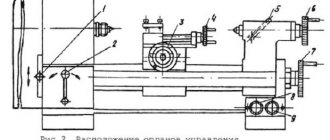
Hydrokinematic scheme
Through a series of kinematic chains and a hydraulic system, the following movements are carried out in the machine:
1. Rotate the spindle of the grinding head.
2. Rotation of the product.
3. Manual and automatic cross feed (machines of models ZA151 and ZA161 have two types of automatic cross feed - continuous plunge feed and periodic feed, carried out when the table is reversed;
machines models ZB151 and ZB 161 do not have automatic plunge feed).
4. Manual and hydraulic movement of the table.
5. Fast hydraulic supply and removal of the grinding headstock.
6. Hydraulic outlet of the tailstock quill. The kinematic chains of the main movement, rotation of the product, manual transverse feed and manual movement of the table are clear from the attached diagrams (see Fig. 21 and 22) and therefore their description is not given. This section describes the design features and operating principles of individual machine components. The design and operation of the hydraulic system are described in the section “Hydraulic drive of machines”.
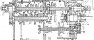
Hydraulic drive of machines
Hydraulic diagram of cylindrical grinding machine 3B151
The hydraulic system of the machine is driven by a pumping unit consisting of a vane pump, a drive motor, a plate filter and an unloading valve (Fig. 21). The pumping unit is mounted on a separate plate fixed to the back of the machine bed stand.
The operation of the machine's hydraulic system is controlled using a hydraulic panel of the GShP-001A type, mounted in a niche in the front part of the bed.
The hydraulic system of the machine performs the following functions:
tailstock quill retraction;Moving the table
The hydraulic movement of the table is started by installing handle 57 (Fig. 21) of a 56 t crane in the position shown in the diagram (handle 10 tilted to the right in Fig. 5). In this case, oil from the pumping unit is supplied to the table reverse spool 43 through the right section of valve 56 and the left section of valve 46. Depending on the position of the spool, the oil enters the right or left cavity of the table movement hydraulic cylinder. Oil from the opposite cavity of this cylinder is forced to drain through the channels of the hydraulic panel, the upper section of the valve 54, the throttle 53 and the retaining valve 55.
The speed of the hydraulic movement of the table during grinding is determined by the setting of the throttle 53.
For ease of operation, the machine provides independent control of the speed of hydraulic movement of the table when grinding and dressing the grinding wheel.
Before editing, it is necessary to turn off the oscillating movement of the grinding headstock spindle with handle 21 (see Fig. 5) and set tap 54 (Fig. 21) to the “Editing” position. In this case, oil is drained from the non-working cavity of the table moving hydraulic cylinder through throttle 52.
The table movement speed during straightening is controlled by adjusting the throttle 52.
When the hydraulic movement of the table is turned off, oil under pressure also enters the hydraulic cylinder for blocking the mechanism for manual movement of the table through the left middle section of valve 25 and disengages the clutch of this mechanism. This makes it impossible to transfer rotation from the rack and pinion to the flywheel.
The table reverse lever is equipped with a pull pin 26. This makes it possible to move the table to the straightening area without disturbing the installation of the reverse stops fixed on the machine table. The machine is equipped with a third reverse stop to limit the movement of the table to the right when dressing the grinding wheel.
The hydraulic movement of the table is turned off by tilting handle 10 to the left in Fig. 5 (tap 56 in Fig. 21). In this case, the right section of the valve 56 closes the line from the pump unit to the spool 43, and the left section of the valve connects the left and right cavities of the table movement cylinder. At the same time, the locking cylinder of the manual table movement mechanism communicates with the drain through the channels of valves 25 and 56, as a result of which the clutch of this mechanism will be activated by a spring and it will be possible to move the table by turning the flywheel 1 (see Fig. 5).
Reverse table
When switching the spool 27 (Fig. 21), which is carried out in the extreme positions of the table through the stops and the reverse lever 28 with the pulling pin 26, oil under pressure is directed to the right or left end of the reversing spool 43 and moves it to the extreme right or left position. As a result, the cavities of the hydraulic cylinder of the table movement are alternately connected with pressure and drainage, which leads to an automatic change in the direction of movement of the table.
The length of the table stroke is determined by the position of the reverse stops, which are fixed in the T-shaped groove of the table and act on pin 26 of the reverse lever.
Throttles 31 serve to regulate the smooth acceleration of the table after reverse.
Moving the table
For the convenience of setting up the machine, it is possible to move the table to the right or left at an adjustable speed with the grinding head retracted and the hydraulic movement of the table turned off. The table movement is controlled by handle 24 of valve 25 (handle 3 in Fig. 5).
The oil flow from the left cavity of the cylinder 19 (Fig. 21) for the quick supply of the grinding head flows to the left end of the spool 42 (through the right section of the starting valve 56) and to the upper end of the spool 29. In this case, the spool 42 will move to the right, connecting the non-working cavity of the table movement cylinder with draining through the right section of valve 25 and opening access to oil under pressure (coming from the pumping unit) to the right middle section of the same valve. At the same time, spool 29 will move down and block the oil drain of the table movement cylinder through throttles 52 and 53.
To move the table, you need to tilt handle 24 to the right or left (depending on the required direction of movement of the table).
In addition, when turning the handle 24, the channels of the left section of the valve 25 separate the right and left cavities of the table movement cylinder, and the channels of the right section of the valve connect the working cavity of this cylinder with pressure through the reversible spool 43; the slot in the right section of the tap will connect the non-working cavity of the cylinder with the drain. At the same time, oil under pressure will flow through the left middle section of valve 25 into the locking cylinder of the manual table movement mechanism and turn it off. When handle 24 is released, this cylinder is connected to the drain through the channels of taps 25 and 56.
The speed of movement of the table during transfer is determined by the angle of inclination of the handle 24, on which the size of the cross-section of the slot of the valve 25 depends.
Periodic feeding of the grinding headstock
Before starting longitudinal grinding with periodic feeding of the grinding head, install valve 33 (handle 5 in Fig. 5) in one of the following positions:
- 1) serve for each move;
- 2) serve with the table reversed to the left;
- 3) serve with the table reversed to the right.
Periodic feed from the plunging mechanism
Switch tap 46 (handle 12 in Fig. 5) to the “Periodic feed” position. Set valve 49 (handle 14 in Fig. 5) to the “From the plunge mechanism” position.
In this case, the oil displaced from the lower cavity of the cylinder 14 flows through the right section of the valve 46 and is blocked by the spool belt 35.
At the moment of switching of spool 27 when the table is reversed, groove a of the sleeve of this spool will connect with groove b, to which oil is supplied under pressure, and the oil flow will be directed to the end of spool 35 through the channels of valve 33 and the groove of spool 44. Spool 35 will move to the lower position, due to whereupon the oil from the plunge cylinder will be directed into the cavity of the dispenser 36, the piston of which, compressing the spring, will move to a preset stop, the position of which determines the amount of periodic feed.
At the same time, oil from groove a will flow through check valve 32 to the end of the table reverse spool 43 and move it to one of the extreme positions, as a result of which the direction of movement of the table will change. The spool 44 will also move to the opposite extreme position, as a result of which the end cavity of the spool 35 will connect with the drain through the channels of the valve 33 and the spool 27. The spool 35 will move upward under the action of the spring, connect the metering cavity with the drain, and the oil will be forced out of it by a spring-loaded plunger. After this, the dispenser is ready to receive the next portion of oil.
To compensate for leaks that disrupt the stability of small feeds, a throttle 34 is provided.
Intermittent feed from ratchet mechanism
Switch tap 46 (handle 12 in Fig. 5) to the “No supply” position. Set valve 49 (handle 14 in Fig. 5) to the “From the ratchet” position.
In this case, when switching spool 27 at the moment of table reverse, groove a of the spool sleeve is connected to groove b, which is under pressure, and the oil through the channels of valve 33 and spool 44 is directed to the left end of the reversible spool 60 and moves it to the right. Then, under oil pressure, the piston of cylinder 45 will move to the right, and the pawl, hinged on the piston and engaged with ratchet wheel 3, will turn the latter by the set number of teeth, producing a feed.
The amount of periodic feed is set by handle 22 (Fig. 5).
After feeding, the reversible spool 60 (Fig. 21) is returned by a spring to its original (left) position. In this case, oil from the line enters the right cavity of cylinder 45 and returns its piston to its original (left) position, after which the periodic feed mechanism is ready to receive the next portion of oil.
Fast approach and retraction of the grinding headstock
Quick approach of the grinding head to the product is carried out by tilting handle 57 (handle 10 in Fig. 5). In this case, oil from the pumping unit enters the right cavity of the quick supply cylinder 19 through the channels of the spool 58, and the left cavity of the cylinder is connected to the drain.
Quick retraction of the grinding head can be done manually (by tilting the handle 57 away from you) or automatically upon completion of the grinding cycle by turning on an electromagnet acting on the quick approach spool 59.
Continuous feed of the grinding headstock (plunging)
Before starting plunge grinding, switch valve 46 (handle 12 in Fig. 5) to the “Continuous feed” position. The left section of valve 46 will close the line between the starting valve 56 and the reversing spool 43. This will eliminate the possibility of hydraulic movement of the table even if the starting handle is accidentally turned on.
Continuous supply of the grinding headstock is activated by tilting the handle 57 of the starting valve towards you (handle 10 in Fig. 5), as a result of which the grinding headstock will be quickly supplied to the product; at the end of the approach, the rollers of the plunge mechanism will rest against the end knuckle 13.
The further movement of the grinding head (plunging) is determined by the rotation of the fist 13, the rotation of which is imparted by the piston-rack of the cutting cylinder 14. The rack, cut on the piston, engages with the ring gear of the fist.
The fist has helical surfaces with two sections of different pitches (4 and 1 mm), which correspond to roughing and finishing feed. Upon reaching the specified size of the product, the cutting mechanism is brought into contact with the rigid stop and feeding (with further rotation of the fist 13) does not occur, i.e., the product is fed out. The nursing time is regulated by setting throttle 51 (throttle 15 in Fig. 5). At the end of nursing, microswitch VK4 sends a command to remove the grinding headstock (switching spool 59 with an electromagnet).
Oil under pressure is supplied to the upper end of the piston-rack from the cavity of the cylinder for the rapid supply of the grinding headstock when (its piston approaches the extreme forward position. From the opposite cavity of the plunge cylinder, oil is forced out to drain through valve 46, spool 47 and throttle 48, the setting of which is determined plunge-in feed speed. At the end of the plunge-in cycle, spool 59 is moved to the lowest position by an electromagnet; the grinding headstock is quickly removed from the workpiece. There is also the possibility of plunge-cut grinding with manual withdrawal of the grinding headstock (by tilting the handle 57 away from you).
Fast feed of the grinding headstock
If the wheel does not come into contact with the workpiece after quickly approaching the grinding headstock, the working feed of the latter can be accelerated to reduce the time of “air grinding” by tilting handle 17 to the right (see Fig. 5). The handle is connected to sleeve 50 (Fig. 21) of throttle 48. After a spark appears, the handle should be released and it will automatically return to its original position; Grinding will continue at the feed rate determined by throttle setting 48.
Tailstock quill retraction
Hydraulic retraction of the tailstock quill can only be carried out when the grinding headstock is retracted. The quill is retracted by foot pedal 7 (see Fig. 5), connected by a system of levers to spool 37 (Fig. 21).
Plunge grinding when working with an active control device
On special request, an active control device is supplied with the machine.
When working with an active control device, after finishing feed, a command is sent to the spool switching solenoid 47; After this, the oil from the lower cavity of the plunge mechanism is drained through the finishing feed throttle 51. Upon reaching the specified size of the product, the device sends a command to the electromagnet of the spool 59, as a result of which the grinding headstock is quickly removed from the product.
In the case of using a desktop active control device 8, oil enters the last supply cylinder from the upper cavity of the plunge cylinder upon completion of the rough feed. Oil is drained from the device supply cylinder through the right cavity of cylinder 19 when the grinding head is quickly withdrawn.
Automatic shutdown of the oscillating mechanism
It is possible to automatically turn off the mechanism for the oscillating movement of the grinding headstock spindle, which in this case will occur when tap 54 is switched to the dressing position. To do this, the hydraulic panel channel communicating with the lower section of the valve 54 must be connected to the cylinder 10 for turning off the mechanism for the oscillating movement of the grinding head spindle.
Removing play in the cross feed mechanism
The play in the engagement of the screw 18 and the cross-feed nut 17 is removed using a hydraulic cylinder 16. The piston rod of this cylinder is constantly pressed against the stop fixed to the body of the grinding head during machine operation. The direction of force acting on the stop is opposite to the direction of feed of the grinding headstock.
Purpose of the metal machine 3B151P
The semi-automatic machine is designed for external grinding of cylindrical and flat conical surfaces in mass production conditions. Grinding is carried out in fixed centers
Technical characteristics of the machine 3B151P
We offer to buy new or overhauled analogues of equipment such as 3B151P cylindrical grinding machine at a competitive price. You can select the appropriate model yourself on our website in the CATALOG section, or by consulting the sales department of our company.
The sale of analogues of the machine model 3B151P is made with 100% prepayment if the equipment is in stock and 50% prepayment when the machine is put into production at the manufacturer and payment of the remaining 50% after notification of its readiness for shipment. Another jointly agreed upon payment procedure is possible.
The warranty for products similar to the product - Cylindrical grinding machine 3B151P is:
- new machines - 12 months,
- after major repairs - 6-12 months.
Manufacturers reserve the right to change the standard configuration and place of production of equipment without notice!
We draw your attention to the fact that the prices indicated on our website are not a public offer, and check the cost of the equipment with our sales managers of machine tools and forging equipment!
If you need to buy a 3B151P cylindrical grinding machine, call:
in Moscow in St. Petersburg in Minsk +375 (17) 246-40-09 in Ekaterinburg in Novosibirsk in Chelyabinsk in Tyumen +7 (3452) 514-886
in Nizhny Novgorod in Samara in Perm in Rostov-on-Don in Voronezh in Krasnoyarsk
in Nur-Sultan;
in Abakan, Almetyevsk, Arkhangelsk, Astrakhan, Barnaul, Belgorod, Blagoveshchensk, Bryansk, Vladivostok, Vladimir, Volgograd, Vologda, Ivanovo, Izhevsk, Irkutsk, Yoshkar-Ola, Kazan, Kaluga, Kemerovo, Kirov, Krasnodar, Krasnoyarsk, Kurgan, Kursk , Kyzyl, Lipetsk, Magadan, Magnitogorsk, Maikop, Murmansk, Naberezhnye Chelny, Nizhnekamsk, Veliky Novgorod, Novokuznetsk, Novorossiysk, Novy Urengoy, Norilsk, Omsk, Orel, Orenburg, Penza, Perm, Petrozavodsk, Pskov, Ryazan, Saransk, Saratov, Sevastopol, Simferopol, Smolensk, Syktyvkar, Tambov, Tver, Tomsk, Tula, Ulan-Ude, Ulyanovsk, Ufa, Khabarovsk, Cheboksary, Chita, Elista, Yakutsk, Yaroslavl and other cities
Toll-free number throughout Russia.
In the CIS countries - Belarus, Kazakhstan, Turkmenistan, Uzbekistan, Ukraine, Tajikistan, Moldova, Azerbaijan, Kyrgyzstan, Armenia in the cities of Nur-Sultan, Bishkek, Baku, Yerevan, Minsk, Ashgabat, Chisinau, Dushanbe, Tashkent, Kiev and others for purchase equipment such as Cylindrical grinding machine 3B151P, call any convenient number listed on our website, or leave your contacts under the ORDER A CALL button at the top of the site - we will call you back.