GOST (short name for State Standard, State Standard, GOST) is one of the important categories of the system of welding standards in the USSR, which is still a standard in modern CIS countries. Adopted by a body such as the Interstate Council for Standardization, Metrology and Certification.
During the period of socialism, all state Welding standards were preserved for the production of products, and were mandatory for use in those areas of technology that were determined by the scope of possible use of GOST.
GOST standards: welding processes
GOST 19521-74 Welding of metals. Classification
GOST 3.1705-81 Unified system of technological documentation. Rules for recording operations and transitions. Welding
GOST 2601-84 Welding of metals. Terms and definitions of basic concepts
GOST 11969-79 Fusion welding. Basic provisions and their designations
GOST 29273-92 Weldability. Definition
GOST 23870-79 Weldability of steels. Method for assessing the effect of fusion welding on the base metal
GOST 30430-96 Arc welding of structural cast iron. Process requirements
GOST 30482-97 Electroslag welding of steels. Process requirements
GOST 29297-92 Welding, high-temperature and low-temperature soldering, soldering of metals. List and symbols of processes
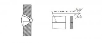
GOST 2.312-72 Unified system of design documentation. Conventional images and designations of seams of welded joints.
GOST 20549-75 Vacuum diffusion welding of working elements of separation and forming dies. Typical technological process
GOST R ISO 17659-2009 Welding. Multilingual terms for welded joints.
GOST R ISO 857-1-2009 Welding and related processes. Dictionary. Part 1. Metal welding processes. Terms and Definitions.
Geometric characteristics
As mentioned above, the geometry of the seams depends on the type of connection. The main geometric dimensions of the sections of butt and fillet welds are presented in the following figure:
Geometric characteristics
- where S is the thickness of the parts;
- e – width of the weld;
- g – convexity;
- m – concavity;
- h – penetration depth;
- t – weld thickness;
- b – gap in the connection;
- k – fillet weld leg;
- p – height;
- a – thickness.
The geometric dimensions are affected by the type of connection and the thickness of the products being welded. These indicators are shown in the following table.
Table with types of welded joints
From the information presented it is clear that all geometric dimensions of welds and parts being connected are interconnected. The length of these elements of welded structures stands out. It depends only on the load on the connection and is completely independent of the geometry of the seam section. The minimum length of the weld must ensure the strength of the connection when the maximum total load is exceeded by 20%. Products are often welded along the entire length of the contact, but in many cases welding is performed in short sections to ensure the necessary strength of the connection. For building structures, the calculation of the length of the weld according to SNiP II-23-81 is carried out based on these criteria.
Calculation of butt weld geometry
The method for checking seams for this type is fully described in the following regulatory documents: SNiP II-23-81 clause 11.1 and SP 16.13330.2011 clause 14.1.14. These documents present different calculation methods, but all of them are derived from the following mathematical formula:
Formula for calculating the geometry of a butt weld
- where N is the maximum tensile or compressive force;
- t – minimum thickness of welded parts;
- lw – seam length;
- Rwy – load resistance;
- γс – tabular coefficient.
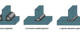
With this type of connection, it is welded over the entire length of the contact, therefore the length of the seam is equal to the length of the joints of the parts being welded, reduced by 2t, twice the thickness of the metal. The width of the seam depends on the shape of the edges and the thickness of the parts. Schemes of design options for butt joints are shown in the following figures.
Design diagrams for butt joints
If during welding work materials are used in accordance with Appendix 2 of SNiP II-23-81, no calculations are made, only visual quality control of the connections made is carried out.
Calculation of fillet weld geometry
Calculation of the geometric dimensions of fillet welds under the influence of a load passing along the axis of the center of gravity is carried out along the selected section, the most dangerous in this connection. This may be a calculation based on the cross-section of the weld metal or the fusion boundaries of materials. The figure below shows both sections.
Fillet weld geometry diagram
In this type of welded joints, stresses of various types act, but the dominant load is the shear force. Fillet welds are checked using the following formulas.
Calculation formula for weld metal
Formula for calculating the fusion boundary
where N is the maximum tensile or compressive force; βf and βz – tabular coefficients for steel; kf – weld leg length; lw – length; Rwf – design shear resistance; Rwz – the same but in the fusion zone; γс – tabular coefficient of operating conditions; γwf and γwz – the same, but for different operating conditions.
The main geometric characteristic of all fillet welds is the size of their leg, i.e. the thickness along the fusion boundaries. The size of the leg depends on the thickness of the parts, material and welding method. You can select the value of this geometric parameter in the table below.
Table of minimum fillet weld legs
Tools for checking seam dimensions
A weld geometric parameters meter is a specialized tool that can be used to measure the main characteristics of these elements of welded structures. Among the variety of such measuring instruments, the following groups of products can be distinguished: templates, universal meters and devices specialized in measuring one parameter. A professional welder’s kit includes several such tools that allow you to measure both parts prepared for welding and the weld itself.
Conclusion
The above information is relevant for connections made using manual electric arc welding. The dimensions of the weld in semi-automatic welding are calculated using other methods. It should be noted that all geometric dimensions of welds are strictly tied to the thickness of the parts being welded and the maximum load that the entire structure must withstand!
GOST: submerged arc welding
GOST 8713-79 Submerged arc welding. Welded connections. Main types, structural elements and dimensions
GOST 11533-75 Automatic and semi-automatic submerged arc welding. Welded connections at acute and obtuse angles. Main types, structural elements and dimensions
GOST welding + in shielding gases
GOST 14771-76 Arc welding in shielding gas. Welded connections. Main types, structural elements and dimensions
GOST 23518-79 Arc welding in shielding gases. Welded connections at acute and obtuse angles. Main types, structural elements and dimensions
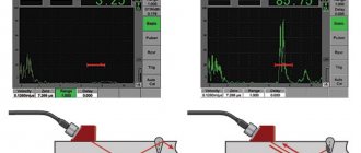
Checking welded joints for permeability
If welding is used in the manufacture of tanks, tightness control is required. To do this, tests for tightness of connections are carried out. Quality control is carried out using gases or liquids.
The essence of the method is based on creating a large pressure difference between the outer and inner areas of the container. With through-hole flaws in the weld, liquid or gas will flow from an area of high pressure to an area of low pressure.
Depending on the substance used and the method of obtaining excess pressure, permeability control is carried out by pneumatics, hydraulics or vacuum.
Pneumatic method
The use of a pneumatic welding quality control method requires pumping the tank with some gas to a pressure of 150% of the nominal pressure.
Then all welds are moistened with soapy water. Bubbles form in places of leakage, which is very easy to fix. For better visualization, an ammonia additive is used, and the seam is covered with a bandage soaked in phenolphthalein. Red spots appear in areas of leakage.
If it is not possible to pump up the container, then use the blowing method. On one side the seam is blown under a pressure of at least 2.5 atmospheres, and on the other it is coated with a soap solution. If there is a defect, it will appear in the form of bubbles.
Hydraulic method
With the hydraulic method of welding quality control, the container being tested is filled with water or oil. An excess pressure is created in the vessel, which is one and a half times more than the nominal pressure.
Then, for a certain time, usually 10 minutes, the area around the seam is tapped with a hammer with a rounded head. If there is a through welding defect, a leak will appear. If the excess pressure is small, then the holding time of the tank is increased to several hours.
GOST: aluminum welding
GOST 14806-80 Arc welding of aluminum and aluminum alloys in inert gases. Welded connections. Main types, structural elements and dimensions
GOST 27580-88 Arc welding of aluminum and aluminum alloys in inert gases. Welded connections at acute and obtuse angles. Main types, structural elements and dimensions
GOST spot welding
GOST 14776-79 Arc welding. Spot welded connections. Main types, structural elements and dimensions
GOST 28915-91 Pulse laser welding. Spot welded connections. Main types, structural elements and dimensions
GOST: pipeline welding
GOST 16037-80 Welded connections for steel pipelines. Main types, structural elements and dimensions
GOST 16038-80 Arc welding. Welded connections for pipelines made of copper and copper-nickel alloy. Main types, structural elements and dimensions
GOST 16310-80 Welded joints made of polyethylene, polypropylene and vinyl plastic. Main types, structural elements and dimensions
GOST 15164-78 Electroslag welding. Welded connections. Main types, structural elements and dimensions
GOST 15878-79 Contact welding. Welded connections. Structural elements and dimensions
GOST 16098-80 Welded joints made of two-layer corrosion-resistant steel. Main types, structural elements and dimensions
GOST 16310-80 Welded joints made of polyethylene, polypropylene and vinyl plastic . Main types, structural elements and dimensions.
GOST 16130-90 Wire and rods made of copper and copper-based alloys for welding. Specifications
GOST standards: welding materials
GOST R EN 13479-2010 Welding materials. General requirements for filler materials and fluxes for fusion welding of metals
GOST R 53689-2009 Welding materials. Technical conditions for the supply of filler materials. Product type, dimensions, tolerances and markings
GOST 7871-75 Welding wire made of aluminum and aluminum alloys. Specifications
GOST 9466-75 Coated metal electrodes for manual arc welding of steels and surfacing. Classification and general technical conditions
GOST R ISO 2560-2009 Welding materials. Coated electrodes for manual arc welding of unalloyed and fine-grained steels . Classification
GOST R ISO 3580-2009 Welding materials. Coated electrodes for manual arc welding of heat-resistant steels . Classification
GOST R ISO 3581-2009 Welding materials. Coated electrodes for manual arc welding of corrosion-resistant and heat-resistant steels . Classification
GOST 2246-70 Steel welding wire. Specifications
Control procedure
The reliability of the analysis depends on the correct preparation of the equipment. Before the steeloscopy procedure of welded seams, it is necessary to properly sharpen the electrode needle on a lathe or grinding wheel. In field conditions, when the operator does not have pre-prepared electrodes, the tip is straightened with a file before each test.
Stages of verification:
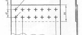
- from the total scope of work of each welder, weld inspection areas measuring 20x20 mm are selected;
- clean the seams until they shine with a wire brush to remove scale;
- fix the equipment in a convenient position so that the arc light enters the analyzer slot;
- mark control points of joints, make corresponding marks in control cards;
- position the head of the apparatus at a distance of 5 mm, perpendicular to the surface being analyzed;
- ignite an arc by touching the metal with an electrode needle;
- focus the eyepiece, visually evaluate the spectrum of evaporating vapors using the control atlas, for this purpose the arc is held for 10–15 seconds;
- record the result in a journal;
- Based on the analysis, a final research protocol is drawn up.
If, during steeloscopy, harmful impurities are found in the weld, additional analysis is carried out at three more points.