, m,
where is the electrical resistivity at 20°C, μΩ m, is the relative magnetic permeability of the material, f is the current frequency, kHz.
When the surface effect is strong, the current practically does not flow through the central part of the conductor, which leads to an increase in active resistance and increased heating of the conductor.
The proximity effect is the redistribution of current lines flowing in adjacent conductors due to their mutual influence. This phenomenon occurs only in the case of a sufficiently strong manifestation of the surface effect, i.e. provided that the penetration depth of the current is sufficiently small compared to the transverse dimensions of the conductor and the cross section of the conductor is only partially occupied by the current.
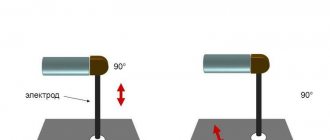
If a conductor carrying a high-frequency current (inductor) is placed above a conducting plate, then the maximum current density in the plate will be under the inductor. The current on the surface of the plate will seem to follow the inductor. This phenomenon allows you to control the distribution of current in the bodies being welded and plays an important role in high-frequency welding.
High frequency welding of plastics
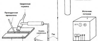
Welding of plastics is carried out according to two schemes: press and roller. In the first method, the configuration of the electrodes coincides with the dimensions of the weld. That is, all sections of the seam are welded at one time. In this case, the electrodes serve not only to supply energy, but also act as a press. In this way you can get any type of joint - butt, overlap, and others.
When it is necessary to weld a thin synthetic film, point electrodes are used, which are fed by a special mechanism with a certain pitch. The second way is using rollers rotating in different directions. One of them is the output for the high-frequency generator, and the second is grounded. Plastic is rolled between them and welding occurs. The result is a long and continuous seam.
This method has a drawback: at high welding speeds, the seam comes out from under the rollers in a heated state, and if the material is thick, then deformation occurs.
It is also difficult to create good electrical capacitance under the rollers. Due to its disadvantages, the roller method is used only for welding thin films.
The most optimal efficiency when welding film thickness of 100 microns. For welding plastics, a whole range of generators with different powers from 1.6 to 10 kW is used. But the frequency at which plastic welding occurs remains unchanged - it is equal to 27.12 MHz. This is a standard that should not be changed.
14.2. Methods of current supply for high-frequency welding.
In high-frequency welding, two mechanisms for heating the surfaces being welded can be distinguished: auto-concentration of current and forced concentration of current.
With auto-concentration of current, currents are passed through each of the welded surfaces, the direction of which at each moment of time is opposite to one another. Due to the proximity effect, self-concentration of current occurs on the surfaces being welded, and this self-concentration is more pronounced the closer the surfaces being welded are to each other and the higher the frequency of the current. This method is most simply implemented with continuous movement of the welded edges converging at a certain angle.
With forced concentration of current, passing a high-frequency current through the inductive wire causes the appearance of a current in the heated products that is opposite in phase to the inductor current. Due to the proximity effect, the induced current will flow through an area determined by the design and location of the inductor.
All current supply methods for high-frequency welding are based on the described principles of heating the surfaces being welded:
1) Conductive current supply during continuous high-frequency butt welding is most widely used in the production of electric welded pipes.
Species and groups
High-frequency welding, depending on the method of transferring energy to the edges, is classified into types:
- Contact . Contacts are placed on the welded edges, to which high-frequency current is supplied.
- Induction . Heating occurs using an inductor, when alternating current flows through it, a magnetic field is generated. When a metal part is placed in the middle of the inductor, an alternating magnetic flux will cause an induction current and heat will be generated in a given area.
HDTV welding processes are divided into 3 groups:
- Pressure with reflow . The mechanism consists in preheating the joined surfaces and their local melting. The molten material is removed from the welding zone during upsetting. A seam is formed between parts in a solid state.
- Pressure without melting . The surfaces to be welded are preheated to a temperature below the melting point of the metal being processed.
- Melting without pressure . The elements are heated until they melt. The weld pool of metal solidifies and a seam is formed without applying pressure.
High frequency welding
The collision of the thrown plate and the base is accompanied by plastic deformation, causing local heating of the surface layers of the metal. As a result of deformation and heating, physical contact develops, activation of the welded surfaces and joints are formed.
The study of plastic deformation in the impact zone based on the distortion of the coordinate grid showed that a strong connection is formed only where the impact is accompanied by mutual displacement of the surface layers of the thrown plate and the base. Where there was no mutual shear, and in particular in the explosion initiation zone, no strong connection was obtained. It is obvious that a “frontal” impact of a thrown plate on the base without a tangential component of velocity and shear deformation in the joint zone does not lead to welding.
Before welding, the surfaces to be joined must be clean (especially for organic contaminants), since neither the action of a cumulative jet nor the vacuum shear deformation upon impact completely eliminates the harmful effects of such contaminants.
Explosion welding makes it possible to weld almost any metal. However, subsequent heating of the welded workpieces can cause intense diffusion in the joint zone and the formation of intermetallic phases. The latter leads to a decrease in the strength of the connection, which at sufficiently high temperatures can drop to almost zero. To prevent these phenomena, explosion welding is carried out through intermediate layers of metals that do not form chemical compounds with the materials being welded. For example, when welding titanium to steel, niobium, vanadium or tantalum are used as an intermediate material.
Explosion welding is used for cladding rods and pipes, internal surfaces of cylinders and cylindrical products (Fig. 3.51). When cladding the rods, pipe 1 (Fig. 3.52, a) is installed with a gap on rod 2. The inner surface of the pipe and the outer surface of the rod are mechanically processed and degreased.
Rice. 3.51. Explosion Clad Press Bearing
An explosive charge 3 is placed on the outer surface of the pipe, which is initiated over the entire section simultaneously so that the explosion is distributed along the charge normal to its axis. To create such a front, a cone of explosives with a detonator 4 at its top is used. To isolate the gap from detonation products and center the pipe relative to the rod, a metal cone 5 is installed in its upper part. In the case of cladding of pipe blanks 6, a rod 2 is installed inside them. The thickness of the cladding pipe can be from 0.5 to 15 mm, and the diameter is not theoretically limited .
When cladding internal surfaces, the scheme shown in Fig. is used. 3.52, b. It involves placing the clad pipe 1 in a massive matrix 2. Inside the pipe 1 with a gap, a cladding pipe 3 is installed with an explosive charge 4 initiated by a detonator 5. For internal cladding of large pipes and cylindrical products for critical purposes, instead of a massive matrix 2, an additional charge is used, located on the outer surface of the clad cylinder and exploded simultaneously with the internal charge.
Rice. 3.52. Scheme of explosion cladding of a rod (a) and the inner surface of a pipe (b)
Magnetic pulse welding
Magnetic-pulse processing of metals is based on the use of electromechanical interaction forces between eddy currents induced in the walls of the workpiece when they intersect the magnetic force lines of a pulsed magnetic field, and the magnetic flux itself. In this case, electrical energy is directly converted into mechanical energy, and the magnetic field pressure pulse acts directly on the workpiece without the participation of any transmission medium.
The installation for magnetic pulse welding (Fig. 3.53) includes: charger 1, consisting of a high-voltage transformer and rectifier; switching device 3, which turns on when an ignition pulse is applied to the auxiliary electrode and causes the battery of high-voltage capacitors 2 to discharge to the inductor 4. The parts to be welded 5 and 6 are overlapped at an angle a to one another with a gap b between them. Inductor 4 is installed on the surface opposite to the one being welded. To prevent movement during welding, part 6 is rigidly fixed in support 7. Fastening part 5 should ensure movement of its welded end in the direction of part 6.
When a battery of capacitors is discharged, a strong magnetic field appears in the gap between the inductor and the workpiece, inducing a current in this workpiece. The interaction of the inductor current with the induced current in the workpiece leads to the emergence of repulsion forces between the inductor 4 and part 5, as a result of which part 5 moves at high speed from the inductor in the direction of the stationary part 6. Upon impact, high pressures develop in the contact zone and a welded joint is formed.
Rice. 3.53. Schematic diagram of magnetic pulse welding
During magnetic-pulse welding, pressure is transferred to the thrown element instantly (at the speed of propagation of the magnetic field), and the movement is transmitted not to individual sections, as in explosion welding, but to the entire thrown part. To ensure consistent movement of the contact zone during welding, the parts are installed with the surfaces to be welded at an angle to one another, the thrown part is processed “on the miter” before welding. The connection, as in explosion welding, is formed as a result of an oblique collision of the surfaces being welded. In this case, conditions are created for cleaning the welded surfaces from oxides and contaminants with a cumulative jet and for intense plastic deformation of metal surfaces with the formation of metallic bonds between them.
The formation of a welded joint is also possible between parallel surfaces. Moreover, due to the scattering of the magnetic field at the ends of the inductor, the pressure distribution along the generatrix of the thrown element is uneven - less at the ends and more in the middle part. Under such loading, the initially rectilinear thrown element, moving towards the moment of meeting with the stationary part, becomes convex, and the flat impact turns into an oblique one, generally propagating in two opposite directions from the initial contact zone.
There are three main schemes for magnetic pulse welding: compression of tubular workpieces using an inductor covering the workpiece (Fig. 3.54, a, b, c); distribution of tubular blanks using an inductor placed inside the blank (Fig. 3.54, d, e, f); deforming sheet blanks with a flat inductor (see Fig. 3.53). To prevent deformation of thin-walled elements during the welding process, a metal mandrel is inserted into pipe 1 (Fig. 3.54, a, b, c), which is removed after welding.
The effect of a pulsed magnetic field on the thrown element depends mainly on the length and number of turns of the inductor, discharge voltage, capacitance of the capacitor bank, discharge energy, inductance and active resistance of the discharge circuit, and the cross-sectional area of the internal surface of the inductor.
Rice. 3.54. Schemes for magnetic pulse welding: 1,2 - workpieces to be welded; 3 - inductor
It is advisable to use this method to obtain all kinds of connections between tubular parts with each other and with other parts, as well as flat parts along the outer and inner contours. The magnetic pulse method can be used to weld almost any materials in homogeneous and heterogeneous combinations. The thickness range of the thrown parts is 0.5-2.5 mm (Fig. 3.55).
Rice. 3.55. Products produced by magnetic pulse welding
One of the main problems in expanding the field of application of magnetic-pulse welding is obtaining strong pulsed magnetic fields with high resistance of the inductor. To solve this problem, it is necessary to create new and improve existing designs of inductors, use high-strength materials for both conductors and mechanical reinforcement elements, and develop new circuits of magnetic-pulse installations.
Ultrasonic welding
The connection with this welding method is formed under the influence of ultrasonic vibrations (frequency 20-40 kHz) and compressive pressures applied to the parts being welded.
Ultrasonic vibrations in welding installations are obtained as follows. Current from an ultrasonic generator (UG) is supplied to the winding of a magnetostrictive transducer (vibrator), which is assembled from plates 0.1-0.2 mm thick (Fig. 1). The material from which they are made is capable of changing its geometric dimensions under the influence of an alternating magnetic field.
If the magnetic field is directed along the stack of plates, then any changes in it lead to shortening or lengthening of the magnetostrictor, which ensures the conversion of high-frequency electrical oscillations into mechanical oscillations of the same frequency.
The vibrator is connected by solder (or glue) to a waveguide or concentrator (instrument), which can amplify the amplitude of the vibrations. Cylindrical waveguides transmit vibrations without changing their amplitude, while stepped, conical concentrators amplify the vibrations. The dimensions and shape of the concentrator are calculated taking into account the required gain. As a rule, a coefficient of 5 is sufficient, providing an amplitude of vibration of the working protrusion at idle speed of 20-30 microns. The dimensions of the waveguide system are selected so that the vibration amplitudes in the welding zone are maximum (elastic vibration curve, Fig. 1).
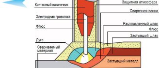
Rice. 1. Diagram of ultrasonic welding: 1 - acoustic unit; 2 — instrument (waveguide); 3 — support adjusting screw; 4 - parts to be welded; 5 — vibrator; 6 - casing
With this welding method, oscillatory movements of ultrasonic frequency destroy surface irregularities (Fig. 2) and the oxide layer. The combined effect of mechanical vibrations and relatively low pressure of the welding waveguide-tool on the parts to be joined ensures the flow of metal in the area of the surfaces being joined without external heat input. As a result of friction caused by the reciprocating movement of compressed contacting surfaces, the surface layers of materials heat up. However, friction is not the dominant source of heat when welding, for example, metals, but its contribution to the formation of a welded joint is significant. Ultrasonic welding can be used to join metal of small thicknesses and is widely used for welding polymer materials. When welding polymers, ultrasonic vibrations are supplied by a waveguide perpendicular to the surfaces being joined, and under their influence intense diffusion occurs - the movement of macromolecules from one part being joined to another.
Rice. 2. Surface profile: a - two assembled copper parts before ultrasonic welding; b - lower part after exposure to ultrasound
A process for welding bone tissue in a living organism has been developed, based on the property of ultrasound to accelerate the polymerization process of certain monomers. Thus, cyacrine, which is an ethyl ester of cyanoacrylic acid, under the influence of ultrasound forms a solid polymer within tens of seconds, while without ultrasound the polymerization process takes several hours. This phenomenon formed the basis for joining, or welding, fragments of bone tissue using cyacrine mixed with bone shavings. Cyacrine hardens and firmly connects to bone tissue, penetrating into its capillaries under the influence of ultrasonic vibrations. The result is a strong connection between the individual parts of the bone.
Ultrasonic welding allows us to solve the problem of attaching aluminum conductor-leads to silicon crystals of semiconductor devices, which connect the devices to external electrical circuits. The range of geometric sizes of contact pads for semiconductor devices is very wide - from several micrometers for integrated circuits and discrete transistors to 400-700 microns for high-power transistors and diodes. Connecting leads is the most labor-intensive operation in the entire device manufacturing cycle.
Several options for ultrasonic welding of crystals with leads have been developed: using longitudinal, transverse, longitudinal-transverse oscillatory systems (Fig. 3).
Rice. 3. Schemes for performing the ultrasonic welding process using longitudinal (a, 6) and longitudinal-transverse (c, d) oscillatory systems
Roll welding
Roll welding
- a high-performance technological process for producing bimetals both from dissimilar metals and from metals that are similar in chemical composition, but differ in properties. This process is used for the production of sheets, strips, tapes, shaped profiles, rods, and wire. The joining of bimetal components occurs during their joint hot or cold plastic deformation, carried out in rolling mills in vacuum or in air.
The initial workpiece for producing bimetal is a package consisting of two different layers of metal in the form of slabs and plates. Typically, single packages are used to obtain one sheet of bimetal (Fig. 3.64, a), double symmetrical packages to obtain two sheets of bimetal (Fig. 3.64, b) and triple packages to obtain three sheets of bimetal, two of which are two-layer, and one three-layer (Fig. 3.64, f).
Rice. 3.64. Designs of packages for rolling welding: 1 - main layer; 2 - cladding layer; 3 - separating layer; 4 — technological bar; 5 - weld
Since reliable connection of layers is ensured by 5-7-fold compression, to obtain a bimetallic sheet 25 mm thick, the initial thickness of the package must be at least 250-350 mm. The width of the slabs used for the base layer in the production of two-layer corrosion-resistant steel sheets is usually 700-1200 mm, and the length is 1700-2500 mm. Slabs of the base layer made of carbon and low-alloy steel are subjected to straightening on a press and mechanical processing along the surface to be welded, followed by degreasing, washing and drying. At the same time, the plates of the cladding layer are prepared.
To reduce the degree of oxidation of the surfaces of the workpieces when they are heated before rolling welding, the packages are sealed with a weld around the perimeter, and in some cases welding is performed in a protective atmosphere (vacuum or inert gas).
Before rolling, the packages are heated in heating shaft or chamber furnaces. The heating temperature, for example, of packages made of carbon and corrosion-resistant steels is 1200-1250 °C.
When producing bimetallic sheets coated with active metals (for example, titanium), a sealed package design is used with a pyrophoric material, cerium, placed inside it, which, when the package is heated, burns and binds environmental oxygen. Reliable joining of easily oxidized metals during hot rolling is achieved on vacuum rolling mills. The packages are rolled (Fig. 3.65) on conventional rolling mills to produce single-layer sheets of similar dimensions.
Rice. 3.65. Roll welding scheme
Cold rolling welding is used to produce two- or three-layer bimetals consisting of a steel base and cladding layers of non-ferrous metals, for example steel + copper, steel + brass, copper + aluminum, aluminum + titanium, aluminum + steel + aluminum. To obtain a high-quality connection of layers in a bimetal, significant deformation during rolling welding and cleanliness of the surfaces being joined are required, and the absence of organic substances is especially important.
When rolling welding, a joint is formed under conditions of forced deformation and a short duration of interaction. Initially, microroughness collapses and contact surfaces increase due to significant stretching, leading to thinning and partial destruction of oxide films. In certain places of contact between the surfaces being welded, areas of setting are formed, between which cavities containing gases remain. The possibility of further increasing the number and area of setting sites is determined by the development of the process of adsorption of residual gases by the metal. With additional plastic deformation, as gas is absorbed by the metal, the setting areas expand, interaction zones are formed, and the joint boundary turns into a continuous interphase boundary.
The formation of a joint ends with the setting of the contact surfaces and the relaxation of stresses to the extent necessary to maintain
Diffusion welding
A distinctive feature of diffusion welding from other pressure welding methods is relatively high heating temperatures (0.5-0.7 Tm) and relatively low specific compressive pressures (0.5-0 MPa) with isothermal exposure from several minutes to several hours.
The formation of a diffusion joint is determined by such physical and chemical processes that occur during welding, such as the interaction of the heated metal with environmental gases, the cleaning of welded surfaces from oxides, the development of high-temperature creep and recrystallization. In most cases, these are diffusion, thermally activated processes.
To reduce the rate of oxidation of workpieces being welded and create conditions for cleaning contact surfaces from oxides during welding, reducing gases, molten salts, fluxes, coatings can be used, but in most cases vacuum or inert gases are used.
Cleaning of metal surfaces from oxides can occur as a result of the development of processes of sublimation and dissociation of oxides, dissolution of oxides due to the diffusion of oxygen into the metal (metal ions into the oxide), reduction of oxides by deoxidizing elements contained in the alloy and diffusing when heated to the metal-oxide interface . Calculations and experiments show that, for example, on steel, oxides are removed most intensively by their reduction with carbon, and on titanium - due to the dissolution of oxygen in the metal.
The convergence of the welded surfaces occurs primarily as a result of plastic deformation of microprotrusions and near-surface layers, caused by the application of external compressive stresses and heating of the metal. In the process of deformation of the welded surfaces, free of oxides, their activation occurs, and with the development of physical contact between such surfaces, their setting is realized.
When diffusion welding of metals of the same name, the welded joint achieves equal strength to the base material in the case when the structure of the joint zone does not differ from the structure of the base material. To do this, grains common to the materials being joined must be formed in the contact zone. This is possible due to the migration of grain boundaries, carried out either by primary recrystallization or by collective recrystallization.
Using diffusion welding in a vacuum, high-quality connections of ceramics with kovar, copper, titanium, heat-resistant and refractory metals and alloys, electric vacuum glasses, optical ceramics, sapphire, graphite with metals, composite and powder materials are obtained.
The workpieces to be connected can be very different in shape and have compact (Fig. 3.66, a) or developed (Fig. 3.66, b, c) contact surfaces. The geometric dimensions of the welded parts range from several micrometers (in the manufacture of semiconductor devices) to several meters (in the manufacture of layered structures).
Rice. 3.66. Some types of structures obtained by diffusion welding
The diffusion welding process can be schematically represented as follows. The workpieces to be welded are assembled in a device that allows pressure to be transferred to the joint zone, evacuated and heated to the welding temperature. Compressive pressure is then applied for a predetermined period of time. In some cases, after the pressure is removed, the product is additionally kept at the welding temperature for a more complete occurrence of recrystallization processes that contribute to the formation of a good-quality joint. At the end of the welding cycle, the assembly is cooled in a vacuum, inert atmosphere or air, depending on the type of equipment.
Depending on the stresses that cause metal deformation in the contact zone and determine the process of formation of a diffusion joint, it is advisable to conventionally distinguish between welding with high-intensity (P ≥ 20 MPa) and low-intensity (P ≤ 2 MPa) force effects. When welding with high-intensity impact, welding pressure is created, as a rule, by a press equipped with a vacuum chamber and a heating device (Fig. 3.67). But with such installations it is possible to weld parts of limited sizes (usually up to 80 mm in diameter (see Fig. 3.66, a). In the manufacture of large-sized two-layer structures (see Fig. 3.66, b), open presses are used. In this case, the parts to be welded are placed before the in the press they are collected in sealed containers, which are evacuated and heated to welding temperature (Fig. 3.68).
Rice. 3.67. Schematic diagram of the installation for diffusion welding (a) and general view of the multi-position installation SDWU-4M (b): and 1 - vacuum chamber; 2 — chamber cooling system; 3 - vacuum system; 4 - high-frequency generator; 5 — press hydraulic system
To eliminate the possibility of loss of stability of the welded elements, transfer of pressure to the welding zone and creation of conditions for locally directed deformation of the welded metal in the joint zone, diffusion welding is carried out in devices using technological liners and blocks to fill the “voids” (intercostal spaces) (see Fig. 3.68 ), which after welding are dismantled or removed by chemical etching.
Rice. 3.68. Technological diagram of diffusion welding with high-intensity force action: a - required design; b - workpieces for welding; c — technological insert elements; g - assembly; d - welding in a press; e - dismantling; g - finished design; 1 — technological inserts; 2-tech container; 3 - press
When welding with high-intensity force, local deformation of the metal in the joint zone, as a rule, reaches several tens of percent, which ensures the stable production of a good-quality joint.
For the manufacture of layered structures (see Fig. 3.66, c), diffusion welding with low-intensity force action is promising, in which the permissible compressive forces are limited by the stability of thin-walled elements. This method of diffusion welding does not require complex special equipment.
When manufacturing flat (or with a large radius of curvature) structures, the compressive force can most easily be provided by atmospheric air pressure Q on the outer surface of the technological equipment when the gas pressure in the connection zone is reduced (Fig. 3.69).
Rice. 3.69. Technological diagram of diffusion welding with low-intensity force action of flat structures: a - required design; b - workpieces for welding; c - assembly; g - welding; d - finished structure; 1 - load-bearing cladding; 2 - ready-made filler; 3 - technological sheets; 4 - membrane
The presence of technological elements (gaskets, membranes, etc.), which have local rigidity and are placed on the outside of the welded elements, eliminates the possibility of loss of stability of the skins in the form of deflections of unsupported areas. The value of welding pressure P is limited by the ultimate buckling stress of the filler σп.з. (P ≤ σп.з.).
When manufacturing structures with a complex curved profile, a technological scheme can be used (Fig. 3.70), in which the neutral gas pressure is perceived directly by the external elements of the structure itself, for example, load-bearing skins, shells. During the welding process, the casing in unsupported areas is deformed (bowed) under gas pressure. This worsens the conditions for the formation of a connection, reduces the cross-section of communicating channels, and worsens the aerodynamic condition of the surface. In this case, P is limited by the stress at which excessive residual deformation of the skins occurs in unsupported areas (P ≤ σp.o.).
Rice. 3.70. Technological diagram of diffusion welding with low-intensity force action of structures of complex shape: a - required design; b - workpieces for welding; c - welding; g - nature of deformation of structural elements during welding; 1 - outer shell; 2 - inner shell
In some cases, it is possible to eliminate the use of external pressure to compress the workpieces being welded, using the phenomena of thermal stress that occurs when heating materials with different linear expansion coefficients. When welding coaxially assembled workpieces, the coefficient of linear expansion of the female part must be less than the coefficient of linear expansion of the male part (see Fig. 3.66, a).
The quality of a joint during diffusion welding in a vacuum is determined by a set of technological parameters, the main of which are temperature, pressure, and holding time. The diffusion processes underlying the formation of a welded joint are thermally activated, therefore an increase in the welding temperature stimulates their development. To reduce the compressive pressure and reduce the welding duration, it is advisable to set the heating temperature of the parts being welded as high as possible; metals have less resistance to plastic deformation. At the same time, it is necessary to take into account the possibility of the development of processes of structural transformation, heterodiffusion, formation of eutectics and other processes leading to changes in the physical and mechanical properties of the metals being welded.
The specific pressure affects the rate of formation of the diffusion joint and the amount of accumulated deformation of the workpieces being welded. In most cases, the higher the specific pressure, the shorter the welding time and the greater the deformation. Thus, when welding in a press using high specific pressures (up to several tens of megapascals), the time of joint formation can be measured in seconds, and the deformation of the metal in the joint zone can be measured in tens of percent. When welding using low specific pressures (tenths of a megapascal), the welding time can be hours, but the deformation of the workpieces being joined is only a fraction of a percent. Thus, the problem of selecting specific pressure should be solved taking into account the type of structures, technological scheme and geometric dimensions of the workpieces being joined, and the welding time should be selected taking into account temperature and specific pressure. When welding dissimilar materials, an increase in welding duration may be accompanied by a decrease in the mechanical characteristics of the joint due to the development of heterodiffusion processes, leading to the formation of brittle intermetallic phases in the joint zone.
To carry out diffusion welding, over 70 types of diffusion-vacuum welding installations have currently been created. The development and creation of installations for diffusion welding is currently being carried out in the direction of unifying systems (vacuum, heating, pressure, control) and welding chambers. By changing the chamber in these installations, you can significantly expand the range of welded assemblies. Some types of structures made by diffusion welding are shown in Fig. 3.71.
Rice. 3.71. Examples of titanium structures made by diffusion welding
Advantages of high-frequency HDTV installations
- The low price allows you to pay for your induction equipment in just six months.
- Great energy savings. This is modern energy-saving equipment based on transistor IGBT modules. Efficiency - more than 90%!
- Small dimensions and weight allow HDTV installations to be located next to the equipment of the subsequent technological cycle.
- Two-block HDTV installations can operate continuously. Single-block HDTV installations are operational up to 80% of the operating cycle.
- They have negligible idle power and do not require warming up.
- They provide rapid heating of workpieces from the inside, from a depth of 1–2 mm.
- Induction soldering is the strongest of all existing types of soldering, due to the vibration of the solder and flux at the frequency of magnetic field generation.
- HDTV units replace electric and gas furnaces and provide high workplace ergonomics and comfortable working conditions.
- There is no high voltage or high frequencies, which is safe for personnel.
- Easy to learn, skills can be acquired in 10 minutes.