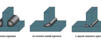
Metal beam joints are connections between multiple metal frames. All main butt joints are created only in industry, that is, they come only in the form of factory versions. Thanks to this, it is possible to significantly increase the entire length of the manufactured products. In addition, the units can be of various types, including those made for ease of installation. But they are usually manufactured in the main building area.
Using them, you can connect separate components, creating one single overall structure. In addition, such connecting parts are much more expensive than factory ones. All this is determined by the need for additional connecting materials, that is, mounting bolts.
Assemblies of metal beams, columns, trusses, and frames
All the main connections between them can be used at the factory, and they are also made during the development of the product itself in industry. Thanks to this, it will be possible to significantly increase the overall length of all products. Moreover, such units from metal beams can be manufactured as an assembly option. Then production will be carried out on the construction site itself. With their help, it will be possible to connect separate components, combining them into one whole structure. Such connection work will cost a little more than the total cost of factory work. In this case, the same mounting bolts are required, and they are made to special order and only in accordance with the beams.
Do-it-yourself I-beams made of wood
When making elements for the support beam, it is best to use laminated veneer lumber, since such a blank corresponds to the correct geometric shapes. At the same time, it is free from deformation, twisting and bending. But you can use timber from any coniferous trees, you just need to comply with the main condition - high-quality drying of the wood.
To independently manufacture I-beam supports, in addition to timber, you will need the following materials and tools:
- A circular saw;
- Wood glue;
- Roulette;
- OSB (orientated strand board);
- Channel for uniform compression of the workpiece;
- Clamps.
Manufacturing procedure
When making an I-beam from wood with your own hands, you must:
Step #1 . Make a calculation and prepare 2 timber of the required size. The greater the height of the beam, the larger the cross-section of the workpieces should be, but in any case the cross-section can be at least 40x60 mm.
Step #2 . In the middle of the products, make a groove with a width equal to the thickness of the slab, and a depth equal to 10-15% of the size of the beam. At home, you can make such a recess on a circular saw using a circular cutter of appropriate thickness.
Step #3 . Make sure that the groove does not have internal defects such as roughness, bending, or chips.
Apply glue over the entire surface of the groove.
Step #4. Insert the slab into the grooves of the upper and lower beams.
Step #5. Compress the entire structure through the prepared channels (corners) using clamps.
Step #6. Leave the entire structure in this form for several hours until completely dry.
After gaining the necessary experience, such wooden I-beams can be made with your own hands with good quality, and used in all kinds of ceilings.
Making a beam with your own hands
Interfaces with special columns made of steel material
A structure supported by beams on columns can be made in the form of a hinged or rigid fastening. But still, if possible, the beams should be supported on top and the entire load should be applied only in the central part of the column profile frame.
Side mounting
When fastening from the side, in addition to compressive loading, a main moment arises in the entire frame when, due to the action of this force, a so-called eccentricity appears, causing the frame to receive a large load, thus leading to excessive consumption of the metal frame of the column.
In order for this load to be transmitted correctly and only through each rib, then it is necessary to ensure that the ribs protrude slightly from their level, usually this can be from 15 to 20 millimeters. This same rib will have to be planed a little so that the total load can then be transferred to the entire area of the rib.
The process of supporting two beams from the top of the columns
In the same way as in the previous one you need to:
- support them over the edge and bring them to the head of the columns;
- here they need to be connected, aligned with each other and secured with bolts;
- It is better not to fasten the bolts from the top, unless you need to make a rigid knot;
- you will have to install the appropriate plates between them so that you don’t have to tighten them together again later.
In addition, you can support two beams at once on one column head using the following design
In this connecting part, the main role is played by the beam located on the bottom flange at the very top of each column.
- In order to transmit the entire lateral force, it will have to be reinforced with an edge.
- We further fasten the rib so that during the installation process it ends up above the column flange itself.
- Next, they need to be connected with bolts, as well as with the help of special overhead plates (make sure that the entire load is located symmetrically).
- Here, too, there is no need to connect all the beams from the top so that a knot does not form.
- In this case, ribs on the columns are not required.
- It is best to leave a small opening between them, 10 or 20 mm in size.
Hinged mounts on columns from the side
For any side mounting, you need to calculate all the columns and create the so-called eccentricity. When supported using hinged fasteners, the load will be transmitted only through the support rib and only to the support table. A small table is usually made from durable sheet steel material, but it is not equal angle. The height of the table can be determined by ensuring that each weld is firmly installed. Here you need to weld the table on three main sides. The total width of this table will have to be made taking into account 20 - 40 mm, slightly larger than the size of the beam rib.
The total diameter of all holes is 3 or 4 mm larger than the diametric parameters of each bolt, but only so that it cannot hang on the bolts, but rather can lie perfectly on this table.
When using a hinged frame, supporting the ribs into the frame column is not required. Between this rib, which serves as a support, and also the column, a metal gasket is mounted, the thickness of which should not exceed 5 mm.
Pairing with columns in a rigid version (welding)
It will be possible to make a rigid connecting part only using bolts, but also by welding. Still, the bolted connection option is considered more technologically advanced. Since in this case almost all parts are developed and also painted in production. When building a frame, you just have to install them and tighten the bolts more tightly.
Several steel spacers will have to be installed between the supporting ribs, as well as the columns, so that the beams and columns fit snugly against each other. That is, in this case there should be no gap between them.
The maximum number of bolts required will have to be calculated only according to the torque that arises.
Design and calculation of assembly (enlargement) joint on high-strength bolts
An assembly joint is a connection between individual parts of structures (sending elements). It is necessary when the weight or dimensions of the beam do not allow it to be transported and mounted entirely. It is located in the middle of the span, which makes it possible to use the same shipping marks. All beam elements are connected in one section of the structure. Such a joint is called combined or universal.
Each beam chord is covered with three overlays on both sides, and the wall - with two vertical overlays, the cross-sectional area of which must be no less than the cross-sectional area of the element they cover, Fig. 2.9.
Fig.2.9. Mounting joint of the main beam with high-strength bolts
Each element of the beam is calculated separately, and the bending moment is distributed between the chords and the wall in proportion to their rigidity. The transverse force at the middle of the span is zero.
Proportion of bending moment attributable to chords
(2.41)
where If
— moment of inertia of the beam chords:
Fraction of bending moment attributable to the wall
(2.42)
where lw
– moment of inertia of the beam wall:
Depending on the span of the main beam and the magnitude of the load, it is recommended to use high-strength bolts with a diameter of 20 mm, 24 mm or 30 mm. The diameter of the holes is taken to be 2-3 mm larger than the diameter of the bolt. The bolts in the joint are placed at minimum distances from each other.
Design force Qbh
, which can be perceived by each friction surface of the connected elements, tightened with one high-strength bolt, is determined by the formula
(2.43)
where Rbh
– calculated tensile strength of high-strength bolts;
. Rbun
values are taken according to table 61*[1] depending on the nominal thread diameter and bolt steel grade;
µ—friction coefficient taken according to Table 36* [1], Table 2.12 [3] depending on the method of processing the surfaces to be joined;
— reliability coefficient accepted according to the table. 36*[1], tab. 2.12 [3] depending on the method of surface treatment, the method of adjusting the tension of the bolts, the nature of the load and the difference in the diameters of holes and bolts;
Abn
– net cross-sectional area of the bolt, determined according to Table 62*[1], Table 2.16 [3] depending on its diameter;
— coefficient of connection operating conditions, depending on the number of « n
» bolts, and taken equal
=0.8 at n
<5;
=0.9 at 5≤ n
<10;
=1.0 at n
≥10.
Design force that can be carried by a single high-strength bolt in a shear connection
(2.44)
where k
– the number of friction surfaces of connected elements.
Note: Nbh
sometimes called the load-bearing capacity of a bolt.
Design of belt joints
The longitudinal force per one belt will be equal to
(2.45)
Each belt is covered with three overlays (Fig. 2.9). The width of the lining on the inside of the belt is 15-25 mm less than the overhang of the belt bef
(for skipping waist seams) and rounded to 5 mm. The thickness of the linings is taken such that the cross-sectional area of the three linings is slightly larger than the cross-sectional area of the belt they overlap.
The number of bolts for attaching the overlays to one chord on one side of the joint will be equal to
(2.46)
Number of bolts « n
» are taken to be even, since they are placed symmetrically relative to the beam wall.
When placing high-strength bolts, the requirements given in Table 39[1] should be taken into account:
A). distances between bolt centers in any direction:
minimum – 2.5dresponse
;
maximum - 8 dots
or 12
t
;
b). distance from the center of the bolt to the edge of the element:
minimum – 1.3 dresponse
;
maximum - 4 dots
or 8
t
;
where t –
thickness of the thinnest outer element
.
To obtain a compact joint, the bolts are placed at minimum distances, rounding them to 5 mm for ease of marking and making holes.
According to paragraph 11.14 [1], the weakening of sections of beam chords and linings with holes for high-strength bolts is taken into account under static loads if the net cross-sectional area is less than 85% of the gross area ( An<0.85A)
; then the conditional cross-sectional area is accepted.
Along the edge (section II, Fig. 2.9) the condition must be met
(2.47)
If the condition is not met, then the bolts are placed in such a way that there are fewer (even) number of bolts along the edge of the joint than in other sections, or the diameter of the bolts is reduced and their number is determined again.
In the middle of the joint (section II-II, Fig. 2.9) the condition must be met
(2.48)
where is the cross-sectional area of the net linings (in section II-II).
If necessary, increase the thickness of the pads.
Wall joint design
For the joint of the wall, the same high-strength bolts are used as for the joint of the belts.
The maximum horizontal force from the bending moment acting on each outer most loaded bolt (Fig. 2.9) will be equal to
(2.49)
where m
– number of vertical rows on one side of the joint; It is recommended to take at least two;
— coefficient depending on the number of rows of bolts vertically “ K”
"; determined according to the table. 2.1.
Table 2.1. Beam web joint coefficients
| TO | 6 | 7 | 8 | 9 | 10 | 11 | 12 | 13 | 14 | 15 | 16 | 17 | 18 |
| 1,40 | 1,56 | 1,71 | 1,88 | 2,04 | 2,20 | 2,36 | 2,53 | 2,69 | 2,86 | 3,02 | 3,19 | 3,35 |
The distance between the outermost rows of bolts will be determined in advance.
mm.
Then from formula (2.49) the joint coefficient is found
Using Table 2.1, determine the number of rows of bolts vertically “ K”
"
Then the bolt pitch “ c
” will be equal to
Meaning " s
» are taken as multiples of 5 mm and check that the requirements for the placement of bolts are met.
Specify the distance amax
Check the load-bearing capacity of the wall joint using the formula
(2.50)
Where
The thickness of the linings on the wall must be at least 8 mm, and their cross-section should be no less than the cross-sectional area of the element they cover, taking into account the requirements for the placement of high-strength bolts, Table 39[1].
For an example of designing an installation joint, see page 167 [2].
Do-it-yourself wooden I-beam from boards
You can make any assembly element from the boards and even build a house, not to mention such a structure as an I-beam. What is such an I-beam?
This is a well-known cross-section of elements, which in shape resembles the letter “H”. Calculations show that when creating such a geometric figure from boards, the rigidity of the load-bearing support is created much greater than that of rectangular or square cross-section products made from timber.
Beam made of boards
Assembling an I-beam
The procedure for making supports with your own hands, when the technology is followed, does not take much time:
- Coating the surface of the groove with glue;
- Connecting a slab of plywood or OSB with the upper and lower beams;
- Pressing, alignment and fixation.
When assembling an I-beam, you need to achieve not only a tight connection, but also to prevent distortion in the structure. To do this, you can use two metal channels along the entire length of the products, which, after being placed on top and bottom, should be secured with clamps.
You can watch the video to see how to assemble the beam step by step:
I-beam floor support