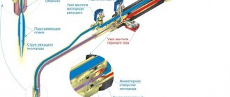
Equipment used: Operating principle of the pumping machine
The electric motor, through a V-belt drive and gearbox, imparts circular motion to two massive cranks located on both sides of the gearbox. The crank mechanism as a whole converts the balancer into reciprocating motion, which rotates on a support axis mounted on a stand. The balancer imparts reciprocating motion to the rope suspension, rods and plunger.
When the plunger moves upward, the discharge valve closes under the action of liquid and all the liquid under the plunger rises upward to a height equal to the length of the plunger stroke. At this time, the well fluid fills the pump cylinder through the suction valve.
As the plunger moves downward, the suction valve closes, the liquid under the plunger is compressed, and the discharge valve opens. Rods connected to a plunger are immersed in the cylinder.
Thus, ShSN is a piston pump of homogeneous action, and as a whole the complex of a pump and rods is of double action.
Liquid from the tubing is squeezed out through a tee into the oil collection pipeline.
Operating principle of a rod pumping unit
A rod pumping unit consists of a downhole pump, which is lowered into the well under a dynamic level on tubing pipes with a diameter of 38-102 mm. and rods with a diameter of 16-25mm. an individual drive, consisting of a pumping machine and an electric motor, and wellhead equipment, which includes: a tee with an oil seal and a faceplate. The top rod, called the polished rod, is passed through the stuffing box and connected to the head of the rocker's balancer by means of a rope hanger and crossbar.
Read also: Which hole to drill for M10 thread
The plunger pump is driven by a pumping machine, where the rotational motion received from the engine using a gearbox, crank mechanism and balancer is converted into reciprocating motion transmitted to the plunger of the sucker rod pump through a string of rods.
As the plunger moves upward, the pressure below it decreases, and liquid from the intertubular space enters the pump cylinder through the open suction valve.
As the plunger moves downwards, the suction valve closes and the discharge valve opens, and the liquid from the cylinder passes into the riser pipes. With continuous operation of the pump, the liquid level in the tubing rises, the liquid reaches the wellhead and flows through the tee into the flow line.
Check valve for gas bypass;
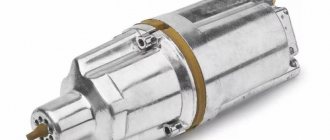
Electric motor on a rotary skid;
Scheme of a rod well pumping unit (USHPU)
Description of pump operation
Downhole rod pumps are designed for pumping liquids from oil wells with a water cut of up to 90%, a temperature of no more than 130 0 C, a hydrogen sulfide content of no more than 50 g/l, and mineralizing water of no more than 10 g/l.
Well pumps are a vertical single-acting design with a fixed cylinder, with a movable metal plunger and ball valves; are lowered into the well using a string of tubing and sucker rods.
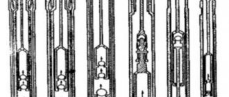
Borehole pumps are manufactured in the following types:
- · НВ1 – plug-in with a lock at the top;
- · НВ2 – plug-in with a lock at the bottom;
- · NN – not plug-in without a catcher;
- · НН1 – not plug-in with a gripping rod;
- · НН2 – not plug-in with a catcher.
Pumps are available in the following designs:
according to the design (execution) of the cylinder:
5 – with a thick-walled solid (sleeveless) cylinder;
C – with a composite (sleeve) cylinder;
according to design features determined by the functional purpose (area of application):
T - with a hollow tubular rod, ensuring liquid lifting through the channel of a column of tubular rods;
A – with a coupling device (only for “NN” type pumps), ensuring coupling of the sucker rod string with the pump plunger;
D 1 – single-stage, two-piston, ensuring the creation of a hydraulic bottom;
D 2 – single-stage, two-piston, providing two-stage compression of the pumped-out liquid (pumps versions D 1 and D 2 – single-stage, single-plunger);
by resistance to the environment:
without designation – resistant to environments containing mechanical impurities up to 1.3 g/l (normal);
And - resistant to environments containing mechanical impurities of more than 1.3 g/l (abrasive resistant).
In the designation of a pump, for example НН25А-44-18-15-2, the first two letters and numbers indicate the type of pump, the next letters indicate the design of the cylinder and pump, the first two numbers indicate the diameter of the pump, the subsequent ones indicate the stroke length of the plunger in mm. and pressure in meters, reduced by 100 times and the last digit is the group of landings.
Inserted well pumps are fixed in tubing pipes on a locking support type OM, with a symbol that includes: type of support; nominal support size; industry standard number.
A downhole rod pump is a positive displacement hydraulic machine, where the seal between the plunger and the cylinder is achieved due to the high strength of their working surfaces and regulated clearances. Depending on the size of the gap (per diameter) in the “cylinder-plunger” pair, pumps are produced in four groups of fits.
Pump cylinders are produced in two versions:
Central bank – solid (without sleeve), thick-walled;
CS is a composite of a set of bushings tightened inside the casing with subs.
Depending on the purpose and area of application of well pumps, plungers and “seat-ball” pairs of valves are produced in various designs, materials and different types of seals of their working surfaces. pumping unit well section
Pump plungers are produced in four versions:
P 1Х – with annular grooves, a cylindrical bore at the upper end and a chrome-plated outer surface;
P2Х - the same, but without a cylindrical bore at the upper end;
P1I - with annular grooves, a cylindrical bore at the upper end and hardening of the outer surface by spraying wear-resistant powder;
P2I - the same, without a cylindrical bore at the upper end.
Seat-ball pairs of pump valves have three designs:
K – with a cylindrical seat and a stainless steel ball;
KB - the same, with a saddle with a collar;
KN – with a cylindrical seat made of carbide and a ball made of stainless steel.
Structurally, all well pumps consist of a cylinder, plunger, valves, lock (for plug-in pumps), connecting and installation parts. When designing pumps, the principle of the maximum possible unification of the specified components and parts is observed for the convenience of the consumer replacing worn parts and reducing the range of required spare parts.
Read also: What is the name of the device for measuring distance
Downhole pumps of the NSV1 design are designed for pumping out low-viscosity liquid from oil wells with a mechanical impurity content of up to 1.3 g/l and free gas at the pump intake of no more than 10%.
The pump consists of a composite cylinder of design TS, on the lower end of which a double suction valve is screwed, and on the upper end - a lock, a plunger of design P1X , movably located inside the cylinder, onto the threaded connections of which are screwed: from below - a double discharge valve, and from above - a plunger cage .
To connect the plunger to the sucker rod string, the pump is equipped with a rod screwed onto the plunger cage and secured with a lock nut. In the bore of the upper sub of the cylinder there is a stop, resting on which, the plunger ensures that the well pump is pulled off the support. The pump valves are equipped with a “seat-ball” pair of KB or K design.
The downhole pump is lowered on a string of sucker rods into the tubing string and secured in a support.
The principle of operation is as follows. As the plunger moves upward, a vacuum is created in the intervalve space of the cylinder, due to which the suction valve opens and the cylinder is filled. With the subsequent downward stroke of the plunger, the intervalve volume is compressed, due to which the discharge valve opens and the liquid entering the cylinder flows into the area above the plunger. Periodic up and down movements of the plunger ensure pumping of the formation fluid and its injection to the surface.
Structurally, well pumps consist of a single-piece cylinder of the CB design with a suction valve screwed onto the lower end. A thrust nipple with a cone is screwed onto the suction valve. A safety valve is located at the upper end of the cylinder to prevent sand from settling in the cylinder when the pump is stopped.
P1X plunger with a discharge valve at the lower end and a plunger cage at the upper end is movably installed inside the cylinder. The pump valves are equipped with a “seat-ball” pair of design K or KB. To connect the pump plunger to the sucker rod string, the pump is equipped with a rod screwed onto the plunger cage and secured with a lock nut.
There is a stop in the bore of the upper sub of the cylinder. The pump is lowered into the tubing string on a string of sucker rods and is secured in the support with its lower part using a thrust nipple with a cone. Such fastening of the pump allows it to be unloaded from pulsating loads. This circumstance ensures its use at great depths of wells.
Downhole pumps of the NSN1 design are designed for pumping low-viscosity liquid containing mechanical impurities up to 1.3 g/l and free gas up to 10% by volume from low-yield, relatively shallow wells.
Structurally, well pumps consist of a composite cylinder of the CS design with a cone seat at the lower end, in the cone bore of which a suction valve is located. P1X plunger movably located with a tip screwed onto the lower end, and a discharge valve onto the upper end.
A gripping rod is screwed onto the suction valve and is located inside the plunger.
Pumps with a diameter of 29, 32 and 44 mm. are equipped with a rod for connecting the sucker rod string to the plunger, and for pumps with a diameter of 57 mm, the plunger is screwed to the sucker rods with a thread on the discharge valve.
The stroke length of the plunger of NSN1 pumps is 900 mm.
The principle of operation of the NSN1 pump is similar to that of the NSV1 pump, however, the cylinder of the NSN1 pump is lowered on the tubing string, and the plunger with valves is on the sucker rod string. When lifting the rods, the head of the gripping rod rests against the tip of the plunger and ensures the removal of the suction valve connected to it to drain from the tubing string.
Well drilling process
Well 890 was laid in accordance with the technological scheme for the development of the terrigenous member of the Lower Carboniferous of the Tournaisian formation of the Pavlovsk field, approved by the Central Commission for the Development of Oil Fields. The well was drilled for the purpose of exploiting oil deposits of the Pavlovskoye field of the Tuneya formation.
Description of the well development process
The wellhead is equipped with fittings type.
ETGr BZ 65x140 No. 419. The fittings are pressed. Sealed.
On June 25, 1989, cumulative perforation PKS-80 was carried out in the well in the interval 1476.0-1492.0 m (-1231.5-1247.5), a total of 288 holes were made.
73 mm were lowered into the well. Tubing to the depth of the feet - rings.
The well has been developed with a compressor.
73 mm. 154 pipes measuring 1458.45 m were lowered through tubing.
In the well in the perforation interval, hydrochloric acid treatment with ammonium sulfate was performed. In 2 hours, at P = 100 atm. 12 m3 pumped. During the treatment, the pressure ranged from 150 to 90 atm. The well has been developed with a compressor. Oil received. The pressure recovery curve before and after acid treatment was recorded by CNIPRA.
On August 29, the well was handed over to NDU Chernushkaneft.
Read also: Hammer for home use rating
In the oil industry, efficiency largely depends on the type of equipment used. For complete equipment and efficient production, a pumping machine is required. This equipment is an integral part of the oil production complex.
Oil pumping device
The machine is mounted on a special concrete base in the form of a foundation. There is also a rack, a platform and a control station for the operator. After completing the work on organizing the platform, a balancer is placed, balanced by a special head, to which a rope suspension is also connected. To ensure force action, the oil pump is equipped with a gearbox and an electric motor. The latter can be located under the platform, but due to the high danger of operating this configuration, such placement is used extremely rarely.
As for the gearbox, it is connected to the balancer through a crank mechanism. This linkage is designed to convert the rotational action of the shaft into a reciprocating function. The task of the control station is also noteworthy. As a rule, its basis is formed by a box complex with electrical filling. It is mandatory to install a manual mechanical brake next to the control relay.
Design features
Pumping machines are designed to transmit translational motion to a deep-well sucker rod pump located at the bottom of the well. To reduce energy costs, equipment must have a unique kinematic design. An additional condition is the use of modern components and components.
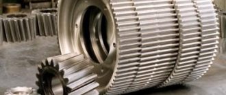
To analyze the functionality and features of the work, it is necessary to familiarize yourself with the design of the pumping machine. It consists of a power unit, the rotational movement from which is supplied to the drive shaft of the gearbox. It houses a crank with a system of counterweights. Connecting rods and traverses are provided to connect the crank to the balancer. In turn, the balancer is mounted on a support post. To reduce energy consumption, a folding head is located at the end of the balancer.
A correctly installed machine has the following performance qualities:
- high efficiency rate. Due to a system of counterweights that will optimize energy costs;
- reliability. The rocking machine is capable of working for a long time. The main thing is to ensure the proper level of lubrication of the moving mechanisms;
- difficulty of installation. For normal operation, pumping machines must be installed on equipped support platforms. Most often they are made by pouring concrete mixture.
Along with this design, non-balancing equipment is used in the oil industry. These models are distinguished by their relatively small size and weight, but at the same time they have a lower efficiency index. Most often they are installed in hard-to-reach areas or places where it is difficult to build a full-fledged foundation.
Electric motors are most often used as a drive, the shaft rotation speed of which does not exceed 1500 rpm. Changing this parameter is carried out using a gearbox or its V-belt analogue.
Main characteristics
Each pumping machine has individual parameters that depend on the required performance properties. However, along with them, this type of equipment has common technical characteristics. To analyze the quality of the machine, it is recommended to familiarize yourself with them.
All pumping machines must have sufficiently high productivity. It is determined by the movement of the rod and its intensity. In addition, performance characteristics should be taken into account: maintainability, size, total weight and difficulty of maintenance. This is important, since the pumping machine is often installed far from populated areas, which makes repairs difficult in the event of a breakdown.
List of main technical characteristics:
- the maximum permissible load on the wellhead rod. It can vary from 30 to 100 kN;
- rod stroke length. Typically it ranges from 1.2 to 3 m;
- torque of the output gearbox shaft. It affects the intensity of the rod movement and can be equal to from 6.3 to 56 kNm;
- the number of strokes of the balancer varies from 1.2 to 15 per minute.
A pumping machine can have a different mass, which depends on the size of its component elements. On average, the weight of the structure ranges from 3.8 to 14 tons. At the same time, the dimensions vary from 4.125 * 1.35 * 3.245 m to 7.95 * 2.25 * 5.83 m. To increase operational safety, the rocking machine is equipped with a control unit that prevents spontaneous starting of the electric motor in the event of a power outage. This also helps to avoid emergency situations due to mechanical breakdowns of components.
Pumping machines can be adjusted according to several parameters, the most important of which are the stroke length of the rod, as well as the number of oscillations of the balancer. Each model has different adjustment methods.
Electric motor pulleys
The electric motor pulleys are quick-changeable due to the conical boring of the body and the use of a conical bushing secured with a nut. Using replaceable pulleys, the number of strokes of the rod suspension point is adjusted.
The rotary slides are designed for mounting the electric motor and provide quick change and tension of V-belts. They are made in the form of a frame, which is hinged at the rear end of the frame of the pumping machine at three points, and on heavy-duty skids (stroke length over 3.5, i) - at four points and two slides bolted transversely to it, on which the electric engine. The rotary slide is turned by rotating the lead screw.
Features of operation
A modern rocking machine belongs to the class of complex equipment and consists of many components. Therefore, its operation requires a detailed study of the device, the main parameters of the equipment and strict adherence to safety precautions.
First of all, you need to install the equipment correctly. This takes into account not only its weight and dimensions, but also the characteristics of the soil. In some cases, for a light-weight model, it is enough to equip a pile foundation. But most often it is necessary to install a reinforced concrete slab, which will evenly distribute the weight of the equipment.
Basic operating rules:
- working personnel must undergo safety training and learn in detail the characteristics and design of the machine;
- implementation of preventive measures to maintain the installation in normal condition;
- in the event of an emergency, the equipment must be turned off and work stopped;
- Troubleshooting should only be done by qualified personnel.
If these rules are followed, the pumping machine will last a long time and at the same time retain its original operational and technical properties.
To visually familiarize yourself with the principle of operation, it is recommended to watch the video material, which shows pumping machines: